
Installation Instructions
Page 1
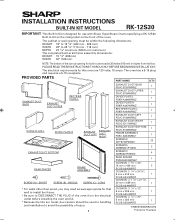
... in Thailand INSTALLATION INSTRUCTIONS BUILT-IN KIT MODEL RK-12S30 IMPORTANT: This Built-In Kit is designed for use with Sharp SuperSteam Ovens specifying a RK-12S30 Built-In Kit on the rating label on the front of the cut-out opening must be 36 inches (915 mm) or higher from the electrical outlet before installing the oven and kit. * Because the kits are 120 volts, 15 amps. The oven has a 5-15 plug and requires a 5-15...
... in Thailand INSTALLATION INSTRUCTIONS BUILT-IN KIT MODEL RK-12S30 IMPORTANT: This Built-In Kit is designed for use with Sharp SuperSteam Ovens specifying a RK-12S30 Built-In Kit on the rating label on the front of the cut-out opening must be 36 inches (915 mm) or higher from the electrical outlet before installing the oven and kit. * Because the kits are 120 volts, 15 amps. The oven has a 5-15 plug and requires a 5-15...

Installation Instructions
Page 2
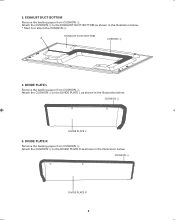
EXHAUST DUCT BACK CUSHION 2 2 Attach the CUSHION 2 at the lower flange of the EXHAUST DUCT UPPER as shown in the illustration below . Attach the CUSHIONS 1 to some parts. 1. EXHAUST DUCT UPPER Remove the backing paper from CUSHION 2. EXHAUST DUCT BACK Remove the backing paper from each side flange of the EXHAUST DUCT BACK as shown in the Illustration below . PREPARATION Follow the directions from 1 to 5 to attach cushions to each CUSHION 1. CUSHION 1 CUSHION 1 EXHAUST DUCT UPPER 2.
EXHAUST DUCT BACK CUSHION 2 2 Attach the CUSHION 2 at the lower flange of the EXHAUST DUCT UPPER as shown in the illustration below . Attach the CUSHIONS 1 to some parts. 1. EXHAUST DUCT UPPER Remove the backing paper from CUSHION 2. EXHAUST DUCT BACK Remove the backing paper from each side flange of the EXHAUST DUCT BACK as shown in the Illustration below . PREPARATION Follow the directions from 1 to 5 to attach cushions to each CUSHION 1. CUSHION 1 CUSHION 1 EXHAUST DUCT UPPER 2.
Installation Instructions
Page 3
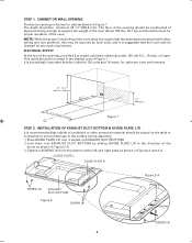
CUSHION 4 DIVIDE PLATE L 5. DIVIDE PLATE R Remove the backing paper from CUSHION 3. EXHAUST DUCT BOTTOM A CUSHION 3 4. EXHAUST DUCT BOTTOM Remove the backing paper from CUSHION 5. Attach the CUSHION 4 to the DIVIDE PLATE L as shown in the Illustration below . * Start A to attach the CUSHION 3. 3. Attach the CUSHION 3 to the DIVIDE PLATE R as shown in the Illustration below. CUSHION 5 DIVIDE PLATE R 3 DIVIDE PLATE L Remove the backing paper from CUSHION 4. Attach the CUSHION 5 to the EXHAUST DUCT BOTTOM as shown in the Illustration below .
CUSHION 4 DIVIDE PLATE L 5. DIVIDE PLATE R Remove the backing paper from CUSHION 3. EXHAUST DUCT BOTTOM A CUSHION 3 4. EXHAUST DUCT BOTTOM Remove the backing paper from CUSHION 5. Attach the CUSHION 4 to the DIVIDE PLATE L as shown in the Illustration below . * Start A to attach the CUSHION 3. 3. Attach the CUSHION 3 to the DIVIDE PLATE R as shown in the Illustration below. CUSHION 5 DIVIDE PLATE R 3 DIVIDE PLATE L Remove the backing paper from CUSHION 4. Attach the CUSHION 5 to the EXHAUST DUCT BOTTOM as shown in the Illustration below .
Installation Instructions
Page 4
... assembly. 1 Place DIVIDE PLATE L/R over 2 caches on the table or countertop to prevent damage to support the weight of the oven (about 150 lbs., 68.1 kg) and should be checked for proper operation of the opening in the wall or cabinet shown in Figures 2 and 2-A. NOTE: While the proper functioning of the oven does not require that a sheet of cardboard or...
... assembly. 1 Place DIVIDE PLATE L/R over 2 caches on the table or countertop to prevent damage to support the weight of the oven (about 150 lbs., 68.1 kg) and should be checked for proper operation of the opening in the wall or cabinet shown in Figures 2 and 2-A. NOTE: While the proper functioning of the oven does not require that a sheet of cardboard or...
Installation Instructions
Page 5
... Figure 3 STEP 4: EXHAUST DUCT BACK INSTALLATION 1 Remove 2 screws (#1) from upper both sides of the oven as shown in Figure 4-A to install the EXHAUST DUCT BACK. (Save 2 screws to be used at step 4-2.) #1 Projection Figure 3-A Figure 4-A 2 Secure EXHAUST DUCT BACK to the oven with the screws (#1) removed at the 4 corners of the oven onto the projections at step 4-1 and...
... Figure 3 STEP 4: EXHAUST DUCT BACK INSTALLATION 1 Remove 2 screws (#1) from upper both sides of the oven as shown in Figure 4-A to install the EXHAUST DUCT BACK. (Save 2 screws to be used at step 4-2.) #1 Projection Figure 3-A Figure 4-A 2 Secure EXHAUST DUCT BACK to the oven with the screws (#1) removed at the 4 corners of the oven onto the projections at step 4-1 and...
Installation Instructions
Page 6
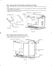
STEP 5: INSTALLATION OF REAR SPACER and EXHAUST DUCT UPPER 1 Attach RECTIFIER PLATE L to the left wall of EXHAUST DUCT UPPER with 4 SCREWS (A) as shown in Figure 5-A. 2 Place EXHAUST DUCT UPPER over the oven and EXHAUST DUCT BACK, and attach REAR SPACER with 2 ...EXHAUST DUCT LEFT Figure 6 6 DIVIDE PLATE L SCREW (A) REAR SPACER EXHAUST DUCT UPPER RECTIFIER PLATE L SCREW (A) SCREW (A) SCREW (A) EXHAUST DUCT UPPER SCREW (A) Figure 5-A EXHAUST DUCT BACK Figure 5-B STEP 6: INSTALLATION OF EXHAUST DUCT LEFT 1 Attach EXHAUST DUCT LEFT to inside of the oven. 2 Tighen with 2 SCREWS (A)...
STEP 5: INSTALLATION OF REAR SPACER and EXHAUST DUCT UPPER 1 Attach RECTIFIER PLATE L to the left wall of EXHAUST DUCT UPPER with 4 SCREWS (A) as shown in Figure 5-A. 2 Place EXHAUST DUCT UPPER over the oven and EXHAUST DUCT BACK, and attach REAR SPACER with 2 ...EXHAUST DUCT LEFT Figure 6 6 DIVIDE PLATE L SCREW (A) REAR SPACER EXHAUST DUCT UPPER RECTIFIER PLATE L SCREW (A) SCREW (A) SCREW (A) EXHAUST DUCT UPPER SCREW (A) Figure 5-A EXHAUST DUCT BACK Figure 5-B STEP 6: INSTALLATION OF EXHAUST DUCT LEFT 1 Attach EXHAUST DUCT LEFT to inside of the oven. 2 Tighen with 2 SCREWS (A)...

Installation Instructions
Page 7
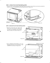
... PLATE R STEP 8: OVEN INSTALLATION CAUTION: Never hold the oven while the other connects it to the electrical outlet. 3 Install the oven into the shelf with 4 SCREWS (A) as shown in Figures 8 and 8-A. Avoid pinching the cord between the oven and any wall as shown in front of the cabinet where the oven is to be installed. Two persons are required to install the oven. 1 Establish center line of opening...
... PLATE R STEP 8: OVEN INSTALLATION CAUTION: Never hold the oven while the other connects it to the electrical outlet. 3 Install the oven into the shelf with 4 SCREWS (A) as shown in Figures 8 and 8-A. Avoid pinching the cord between the oven and any wall as shown in front of the cabinet where the oven is to be installed. Two persons are required to install the oven. 1 Establish center line of opening...
Installation Instructions
Page 8
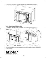
... in Figures 8-B. For any other assistance or information about this product, please call SHARP's Customer Assistance Center 1-800-BE-SHARP. ® SHARP ELECTRONICS CORPORATION Sharp Plaza, Mahwah, NJ 07495-1163 8 SCREW (B) Figure 8-B STEP 9: FRAME ASSEMBLY INSTALLATION 1 Attach FRAME ASSEMBLY and tighten 4 SCREWS (C) as shown in Figure 9 and Figure 9-A. 4 Secure EXHAUST DUCT BOTTOM to remove or replace the drip tray.
... in Figures 8-B. For any other assistance or information about this product, please call SHARP's Customer Assistance Center 1-800-BE-SHARP. ® SHARP ELECTRONICS CORPORATION Sharp Plaza, Mahwah, NJ 07495-1163 8 SCREW (B) Figure 8-B STEP 9: FRAME ASSEMBLY INSTALLATION 1 Attach FRAME ASSEMBLY and tighten 4 SCREWS (C) as shown in Figure 9 and Figure 9-A. 4 Secure EXHAUST DUCT BOTTOM to remove or replace the drip tray.


