Service Manual
Page 2
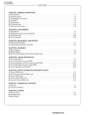
...5-1 [2] Circuit description of control PWB 5-2 [3] Circuit description of TEL/LIU and Hook SW PWB 5-21 [4] Circuit description of power supply PWB 5-23 [5] Circuit description of CIS UNIT 5-24 CHAPTER 6. MECHANICAL DESCRIPTION [1] Mechanical description 3-1 [2] Disassembly, assembly, lubrication 3-11... [4] Error code table 2-27 CHAPTER 3. UX-4000MU FO-2950MU/C CONTENTS CHAPTER 1. CIRCUIT SCHEMATICS AND PARTS LAYOUT [1] Control PWB circuit 6-1 [2] TEL/LIU and Hook SW PWB circuit 6-12 [3] Printer PWB circuit 6-14 [4] Power supply PWB circuit 6-17 [5] Operation panel PWB ...
...5-1 [2] Circuit description of control PWB 5-2 [3] Circuit description of TEL/LIU and Hook SW PWB 5-21 [4] Circuit description of power supply PWB 5-23 [5] Circuit description of CIS UNIT 5-24 CHAPTER 6. MECHANICAL DESCRIPTION [1] Mechanical description 3-1 [2] Disassembly, assembly, lubrication 3-11... [4] Error code table 2-27 CHAPTER 3. UX-4000MU FO-2950MU/C CONTENTS CHAPTER 1. CIRCUIT SCHEMATICS AND PARTS LAYOUT [1] Control PWB circuit 6-1 [2] TEL/LIU and Hook SW PWB circuit 6-12 [3] Printer PWB circuit 6-14 [4] Power supply PWB circuit 6-17 [5] Operation panel PWB ...

Service Manual
Page 3
...Height: 6.7" (169 mm) Weight Approx. 13.4 lbs. (6.1kg) * Based on ITU-T (CCITT) Test Chart #1 at standard resolution in Sharp special mode, excluding time for use the fax machine in conjunction with any of these services, you may experience errors during transmission and reception of... (4% page coverage, letter paper) Initial starter cartridge (included with fax machine): Approx. 1,875 pages Replacement cartridge (UX-400ND): Approx. 3,750 pages Drum cartridge yield Initial starter cartridge (included with supplies, please don't use new supplies, when supply changes are required. 1 - 1
...Height: 6.7" (169 mm) Weight Approx. 13.4 lbs. (6.1kg) * Based on ITU-T (CCITT) Test Chart #1 at standard resolution in Sharp special mode, excluding time for use the fax machine in conjunction with any of these services, you may experience errors during transmission and reception of... (4% page coverage, letter paper) Initial starter cartridge (included with fax machine): Approx. 1,875 pages Replacement cartridge (UX-400ND): Approx. 3,750 pages Drum cartridge yield Initial starter cartridge (included with supplies, please don't use new supplies, when supply changes are required. 1 - 1

Service Manual
Page 17
.../3KV (VCKYQY3FB102K) • Diode: SHV-03 (VHDSHV03///-1) UX-4000MU FO-2950MU/C Output +5V +24VH +24V* Voltage limits 4.75V~5.25V 23.04V~24.96V 23.04V~24.96V Connector PIN No. Output voltage settings Power Supply PWB 1 CN101 12 Printer PWB 1 CNPW 12 Fig. 1 2. Install the power supply unit in the machine. 2. High voltage power...
.../3KV (VCKYQY3FB102K) • Diode: SHV-03 (VHDSHV03///-1) UX-4000MU FO-2950MU/C Output +5V +24VH +24V* Voltage limits 4.75V~5.25V 23.04V~24.96V 23.04V~24.96V Connector PIN No. Output voltage settings Power Supply PWB 1 CN101 12 Printer PWB 1 CNPW 12 Fig. 1 2. Install the power supply unit in the machine. 2. High voltage power...

Service Manual
Page 44
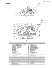
...document set in the facsimile. 3 - 1 manuals4you.com Moreover, the separation securely done by the feed roller to the paper width. Fig. 3 3-3. UX-4000MU FO-2950MU/C CHAPTER 3. General view Fig. 2 The hopper is used to align documents with the pulse motor. 2) When a specified number of ... 2. ment. 3-2. Hopper mechanism 3-1. If the front sensor is off (no document is set up in the hopper), the next document is supplied and fed nearly when the last document is employed. Facsimile block 1-1. Loading the documents 1) Make sure that the documents are of suitable size ...
...document set in the facsimile. 3 - 1 manuals4you.com Moreover, the separation securely done by the feed roller to the paper width. Fig. 3 3-3. UX-4000MU FO-2950MU/C CHAPTER 3. General view Fig. 2 The hopper is used to align documents with the pulse motor. 2) When a specified number of ... 2. ment. 3-2. Hopper mechanism 3-1. If the front sensor is off (no document is set up in the hopper), the next document is supplied and fed nearly when the last document is employed. Facsimile block 1-1. Loading the documents 1) Make sure that the documents are of suitable size ...
Service Manual
Page 45
...transfer pinch roller 36 Rear plate 37 1st. PARTS NAME 21 PIN sensor 22 Toner supply roller 23 Developing roller 24 Transfer charger roller 25 Photoconductor drum 26 Discharge brush 27 ... 32 1st. transfer pinch roller 38 ORG sensor 39 Front sensor 3 - 2 Paper Path Print Exit UX-4000MU FO-2950MU/C Document Exit 5. transfer roller 35 2nd. PARTS NAME 1 Fusing temperature sensor (thermistor)...Third mirror 8 Developing doctor 9 First mirror 10 Laser start position sensor 11 Toner sensor 12 Scanner motor 13 Second mirror 14 Scanner mirror 15 Laser unit 16 Paper empty detector 17 Paper feed ...
...transfer pinch roller 36 Rear plate 37 1st. PARTS NAME 21 PIN sensor 22 Toner supply roller 23 Developing roller 24 Transfer charger roller 25 Photoconductor drum 26 Discharge brush 27 ... 32 1st. transfer pinch roller 38 ORG sensor 39 Front sensor 3 - 2 Paper Path Print Exit UX-4000MU FO-2950MU/C Document Exit 5. transfer roller 35 2nd. PARTS NAME 1 Fusing temperature sensor (thermistor)...Third mirror 8 Developing doctor 9 First mirror 10 Laser start position sensor 11 Toner sensor 12 Scanner motor 13 Second mirror 14 Scanner mirror 15 Laser unit 16 Paper empty detector 17 Paper feed ...
Service Manual
Page 48
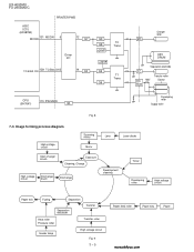
Image forming process diagram High voltage circuit Scanning mirror Mirror Lens Laser diode Main charger brush Exposure Cleaning, Charge High voltage circuit Dischange brush Dischange Development cleaning ...Pressure roller Transfer roller Heater lamp High voltage circuit Fig. 9 3 - 5 Paper feed roller Paper tray Paper manuals4you.com UX-4000MU FO-2950MU/C PRINTER PWB ASIC IC15 (LR38784) 131 MCON 5 MCON 12 Q7 Driver IC1 TC-BIAS ON 129 TC/Bias ON 3 14 Q3... TC DC 100V Bias Transfer roller Doctor CPU (SH7041) 115 PW MSIN Q4 Developing roller Supply roiier Fig. 8 7-3.
Image forming process diagram High voltage circuit Scanning mirror Mirror Lens Laser diode Main charger brush Exposure Cleaning, Charge High voltage circuit Dischange brush Dischange Development cleaning ...Pressure roller Transfer roller Heater lamp High voltage circuit Fig. 9 3 - 5 Paper feed roller Paper tray Paper manuals4you.com UX-4000MU FO-2950MU/C PRINTER PWB ASIC IC15 (LR38784) 131 MCON 5 MCON 12 Q7 Driver IC1 TC-BIAS ON 129 TC/Bias ON 3 14 Q3... TC DC 100V Bias Transfer roller Doctor CPU (SH7041) 115 PW MSIN Q4 Developing roller Supply roiier Fig. 8 7-3.

Service Manual
Page 49
When the OPC is exposed to laser beam, the electric resistance of the exposed section falls and electric charge is connected to charge the brush. UX-4000MU FO-2950MU/C c. a. A high voltage of AC 600V (P-P) and DC-850V are applied to the drum ground. It positively charges paper ... Toner is supplied to the developing roller. It is flexible and is charged to visible images by the invertor system, and is removed. Toner stirring plate This plate stirs toner in the Printer PWB) A high voltage is generated by the developing unit. A high voltage of AC 600V (P-P) and DC...
When the OPC is exposed to laser beam, the electric resistance of the exposed section falls and electric charge is connected to charge the brush. UX-4000MU FO-2950MU/C c. a. A high voltage of AC 600V (P-P) and DC-850V are applied to the drum ground. It positively charges paper ... Toner is supplied to the developing roller. It is flexible and is charged to visible images by the invertor system, and is removed. Toner stirring plate This plate stirs toner in the Printer PWB) A high voltage is generated by the developing unit. A high voltage of AC 600V (P-P) and DC...

Service Manual
Page 51
UX-4000MU FO-2950MU/C On the other hand, when an area of OPC drum which was not exposed to the laser beam and did not lose its ... o form v i s ible images. As a result, unnecessary toner on the OPC drum is attracted by the toner supply roller and the developing roller. The quantity of toner are transferred onto the paper. 3 - 8 When an area of DC.... Developing roller Doctor : Toner (Negatively charged) Scraper Toner supply roller 100V OPC drum Exposed area (Exposed to laser beam) Non-exposed area (Not exposed to laser beam) Grounding sheet DC -310V OPC drum Aluminum layer (...
UX-4000MU FO-2950MU/C On the other hand, when an area of OPC drum which was not exposed to the laser beam and did not lose its ... o form v i s ible images. As a result, unnecessary toner on the OPC drum is attracted by the toner supply roller and the developing roller. The quantity of toner are transferred onto the paper. 3 - 8 When an area of DC.... Developing roller Doctor : Toner (Negatively charged) Scraper Toner supply roller 100V OPC drum Exposed area (Exposed to laser beam) Non-exposed area (Not exposed to laser beam) Grounding sheet DC -310V OPC drum Aluminum layer (...
Service Manual
Page 54
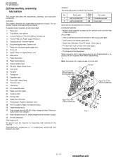
... 12. Lock lever 16. Separate nails 19. Fusing roller 26. High voltage terminal DR-MC (High voltage terminal: Photocon- Printer PWB unit, Power supply PWB unit 5. Document guide lower, Scanner unit 7. Paper feed solenoid 13. PIN actuator (Paper in this machine. Separate plate..., Document guide upper unit 8. Fusing unit 18. Paper exit roller upper 24. ductor drum main charger) 31. No. Panel unit 2. UX-4000MU FO-2950MU/C [2] Disassembly, assembly, lubrication This chapter describes the disassembly, assembly, and lubrication procedures. (Contents) This chapter describes the ...
... 12. Lock lever 16. Separate nails 19. Fusing roller 26. High voltage terminal DR-MC (High voltage terminal: Photocon- Printer PWB unit, Power supply PWB unit 5. Document guide lower, Scanner unit 7. Paper feed solenoid 13. PIN actuator (Paper in this machine. Separate plate..., Document guide upper unit 8. Fusing unit 18. Paper exit roller upper 24. ductor drum main charger) 31. No. Panel unit 2. UX-4000MU FO-2950MU/C [2] Disassembly, assembly, lubrication This chapter describes the disassembly, assembly, and lubrication procedures. (Contents) This chapter describes the ...
Service Manual
Page 57
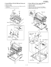
Remove five screws, and remove printer unit. 1 1 UX-4000MU FO-2950MU/C 4. Control PWB unit, TEL/LIU PWB unit, Printer unit 1 Remove six screws. 2 Remove four cables. 3 Remove two connectors, and remove Control PWB unit and TEL/ 4 LIU PWB unit. Printer PWB unit, Power supply PWB unit 1 Remove four screws, and remove Printer unit. 2 Remove four cables. 3 Remove...
Remove five screws, and remove printer unit. 1 1 UX-4000MU FO-2950MU/C 4. Control PWB unit, TEL/LIU PWB unit, Printer unit 1 Remove six screws. 2 Remove four cables. 3 Remove two connectors, and remove Control PWB unit and TEL/ 4 LIU PWB unit. Printer PWB unit, Power supply PWB unit 1 Remove four screws, and remove Printer unit. 2 Remove four cables. 3 Remove...

Service Manual
Page 71
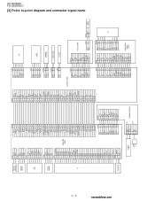
...- 2 LCD 14 CNLCD OPERATION PANEL PWB 22 TX MOTOR 6 PRINTER MOTOR 4 LASER AUTO POWER SCANING MOTOR 5 CONTROL PWB 9 Beam Detector PWB 3 PC LSU UNIT TONER SENSOR 5 PICKUP SOLENOID 2 36 CNPL CNTNR CNLSU CNMMT CNMT CNPN UX-4000MU FO-2950MU/C CN101 CNPW SPEAKER CIS 2 7 CNCIS CONTROL... PWB CNSP 12 FJ HANDSET CNLIUA CNLIUA CNPRT 50 CNPRT PRINTER PWB HIGH VOLTAGE CIRCUIT CNPC CNFM TEL/LIU PWB CNRTH CNFUSE 2 3 THERMAL FUSE UNIT THERMISTOR HEATER LAMP 2 CN2 INTERLOCK SWITCH POWER SUPPLY ...
...- 2 LCD 14 CNLCD OPERATION PANEL PWB 22 TX MOTOR 6 PRINTER MOTOR 4 LASER AUTO POWER SCANING MOTOR 5 CONTROL PWB 9 Beam Detector PWB 3 PC LSU UNIT TONER SENSOR 5 PICKUP SOLENOID 2 36 CNPL CNTNR CNLSU CNMMT CNMT CNPN UX-4000MU FO-2950MU/C CN101 CNPW SPEAKER CIS 2 7 CNCIS CONTROL... PWB CNSP 12 FJ HANDSET CNLIUA CNLIUA CNPRT 50 CNPRT PRINTER PWB HIGH VOLTAGE CIRCUIT CNPC CNFM TEL/LIU PWB CNRTH CNFUSE 2 3 THERMAL FUSE UNIT THERMISTOR HEATER LAMP 2 CN2 INTERLOCK SWITCH POWER SUPPLY ...
Service Manual
Page 72
...DG 31 NINIT 32 NFAULT 33 N.C. 34 N.C. 35 N.C. 36 nSelecton CNFM 1 VFMOUT 2 N.C. 3 MG PRINTER PWB CNPRT POUT- 1a PWMSIN 1b PIN- 2a DOP- 2b TSEN 3a 24VS 3b MEN- 4a MA ... 8 PWRLY9 HLON10 +24V 11 +24V 12 ZC HEATER LAMP 1 HLL 2 N.C. 3 HLN 1L 2 N.C. 3N CN2 POWER SUPPLY CN1 CNPRT 1a POUT1b PWMSIN 2a PIN2b DOP3a TSEN 3b 24VS 4a MEN4b MA 5a MB 5b VIDEO 6a SAMP 6b SYNC7a APCSTT ...SEN3 PANEL 21 SEN4 PWB 22 B4SNS HOOK SW PWB UX-4000MU FO-2950MU/C [3] Point- to-point diagram and connector signal name manuals4you.com 4 - 3 PICK UP SOLENOID PRINTER MOTOR LSU UNIT TONER SENSOR PC FAN MOTOR CNPL 1 ...
...DG 31 NINIT 32 NFAULT 33 N.C. 34 N.C. 35 N.C. 36 nSelecton CNFM 1 VFMOUT 2 N.C. 3 MG PRINTER PWB CNPRT POUT- 1a PWMSIN 1b PIN- 2a DOP- 2b TSEN 3a 24VS 3b MEN- 4a MA ... 8 PWRLY9 HLON10 +24V 11 +24V 12 ZC HEATER LAMP 1 HLL 2 N.C. 3 HLN 1L 2 N.C. 3N CN2 POWER SUPPLY CN1 CNPRT 1a POUT1b PWMSIN 2a PIN2b DOP3a TSEN 3b 24VS 4a MEN4b MA 5a MB 5b VIDEO 6a SAMP 6b SYNC7a APCSTT ...SEN3 PANEL 21 SEN4 PWB 22 B4SNS HOOK SW PWB UX-4000MU FO-2950MU/C [3] Point- to-point diagram and connector signal name manuals4you.com 4 - 3 PICK UP SOLENOID PRINTER MOTOR LSU UNIT TONER SENSOR PC FAN MOTOR CNPL 1 ...

Service Manual
Page 73
... scan processor to the image buffer within the ASIC (IC15) and sent to the printer PWB in the off -hook mode in Fig. 1. 2. Operational description Operational descriptions are two ways of the unit. UX-4000MU FO-2950MU/C 3. CHAPTER 5. The data is then converted from parallel to serial...when the machine is in stand-by the LIU in the on printer PWB. CIRCUIT DESCRIPTION [1] Circuit description 1. PWB configuration AC CORD FAN MOTOR PC HEATER LAMP POWER SUPPLY PWB PRINTER PWB LSU UNIT PICK UP SOLENOID PRINTER MOTOR TONER SENSOR LINE CABLE TEL/LIU PWB CONTROL PWB THERMAL FUSE...
... scan processor to the image buffer within the ASIC (IC15) and sent to the printer PWB in the off -hook mode in Fig. 1. 2. Operational description Operational descriptions are two ways of the unit. UX-4000MU FO-2950MU/C 3. CHAPTER 5. The data is then converted from parallel to serial...when the machine is in stand-by the LIU in the on printer PWB. CIRCUIT DESCRIPTION [1] Circuit description 1. PWB configuration AC CORD FAN MOTOR PC HEATER LAMP POWER SUPPLY PWB PRINTER PWB LSU UNIT PICK UP SOLENOID PRINTER MOTOR TONER SENSOR LINE CABLE TEL/LIU PWB CONTROL PWB THERMAL FUSE...

Service Manual
Page 75
...manual reset condition is impossible. IRQOUT 5,46 O Interruption demand Shows that the bus right has been released to peripheral devices. UX-4000MU FO-2950MU/C SH7041 (IC5) Terminal descriptions Classification Code Terminal No. Clock PLL Vcc 104 I Interruption demand Maskable interruption... demand terminal. CK 107 O System clock Supplied to the external device. BACK 30,37 O Bus right demand Shows that the interrupt factor has occurred. acknowledge The ...
...manual reset condition is impossible. IRQOUT 5,46 O Interruption demand Shows that the bus right has been released to peripheral devices. UX-4000MU FO-2950MU/C SH7041 (IC5) Terminal descriptions Classification Code Terminal No. Clock PLL Vcc 104 I Interruption demand Maskable interruption... demand terminal. CK 107 O System clock Supplied to the external device. BACK 30,37 O Bus right demand Shows that the interrupt factor has occurred. acknowledge The ...

Service Manual
Page 83
... above voltages. • MCON This signal is outputted to turn on /off the transfer charger and the developing bias voltage. Electrical connection CONTROL PWB PRINTER PWB ASIC IC15 (LR38784) 131 MCON 5 12 Q7 Driver IC1 129 TC/Bias ON 3 14 Q3 Q9 Q8 +24VP T2 Transformer +24VP Q5... T1 Transformer Q6 CPU (SH7041) PW MSIN 115 Q4 CNPRT Fig. 8 5 - 11 UX-4000MU FO-2950MU/C Charger roller MC OPC DRUM Separation electrode TC DC 100V Bias Transfer roller Doctor Developing roller Supply roliler As a result, the main charger voltage is to the secondary side of this signal is...
... above voltages. • MCON This signal is outputted to turn on /off the transfer charger and the developing bias voltage. Electrical connection CONTROL PWB PRINTER PWB ASIC IC15 (LR38784) 131 MCON 5 12 Q7 Driver IC1 129 TC/Bias ON 3 14 Q3 Q9 Q8 +24VP T2 Transformer +24VP Q5... T1 Transformer Q6 CPU (SH7041) PW MSIN 115 Q4 CNPRT Fig. 8 5 - 11 UX-4000MU FO-2950MU/C Charger roller MC OPC DRUM Separation electrode TC DC 100V Bias Transfer roller Doctor Developing roller Supply roliler As a result, the main charger voltage is to the secondary side of this signal is...

Service Manual
Page 86
...Before reaching the curved mirror, the laser beam enters the photo sensor on the value of the heat roller. When this signal is supplied to the heater lamp to the ...of the thermistor which detects the surface temperature of RTH voltage. 5 - 14 manuals4you.com UX-4000MU FO-2950MU/C g. The heater lamp is controlled (turned on the heater lamp. • ...is turned on/off the heater lamp. The laser beam reflected by the scanning mirror is directed to reach the photoconductor drum. The laser beam reflected by the first reflection mirror. PRINTER PWB +24V CNLSU 1 +24V 2 DG 3...
...Before reaching the curved mirror, the laser beam enters the photo sensor on the value of the heat roller. When this signal is supplied to the heater lamp to the ...of the thermistor which detects the surface temperature of RTH voltage. 5 - 14 manuals4you.com UX-4000MU FO-2950MU/C g. The heater lamp is controlled (turned on the heater lamp. • ...is turned on/off the heater lamp. The laser beam reflected by the scanning mirror is directed to reach the photoconductor drum. The laser beam reflected by the first reflection mirror. PRINTER PWB +24V CNLSU 1 +24V 2 DG 3...
Service Manual
Page 87
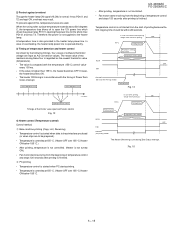
...control and stops 120 seconds after printing is regarded as A/D conversion values. If lower, the heater becomes ON. • The heater ON timing is not supplied to the heater lamp. Heater ON below 155 °C.) • After printing, temperature is not controlled. (Heater is not turned ON.) • ...are to open the 12V power line which drives the power relay RY101, opening the power line for the photo triac PD101 and triac T2. UX-4000MU FO-2950MU/C • After printing, temperature is not controlled. • Fan motor starts revolving from the start of temperature control and...
...control and stops 120 seconds after printing is regarded as A/D conversion values. If lower, the heater becomes ON. • The heater ON timing is not supplied to the heater lamp. Heater ON below 155 °C.) • After printing, temperature is not controlled. (Heater is not turned ON.) • ...are to open the 12V power line which drives the power relay RY101, opening the power line for the photo triac PD101 and triac T2. UX-4000MU FO-2950MU/C • After printing, temperature is not controlled. • Fan motor starts revolving from the start of temperature control and...

Service Manual
Page 90
UX-4000MU FO-2950MU/C k. The interval between Pin On and point D is...(B-C) = 35.7069 mm If top margin is a registered trademark of compact system enclosures for 9 msec. Pout sensor Paper exit roller LASER Process speed 50mm/sec OPC drum speed 49mm/sec=(50x0.98) Discharge brush nip 5.7523mm Fusing 9.3389mm(A-B) 8.3769mm(B-C) B C A... 8085) - The modem satisfies the requirements specified in the 128 pin PQFP. The modem's small size, single voltage supply, and low power consumption allow the design of conexant systems, Inc. 5 - 18 manuals4you.com The base machine resolution...
UX-4000MU FO-2950MU/C k. The interval between Pin On and point D is...(B-C) = 35.7069 mm If top margin is a registered trademark of compact system enclosures for 9 msec. Pout sensor Paper exit roller LASER Process speed 50mm/sec OPC drum speed 49mm/sec=(50x0.98) Discharge brush nip 5.7523mm Fusing 9.3389mm(A-B) 8.3769mm(B-C) B C A... 8085) - The modem satisfies the requirements specified in the 128 pin PQFP. The modem's small size, single voltage supply, and low power consumption allow the design of conexant systems, Inc. 5 - 18 manuals4you.com The base machine resolution...

Service Manual
Page 93
... composed of RHS signal. (RHS is in telephone is being used. 5 - 21 Surge protection circuit 2. HS LOW: EXT. Hybrid circuit 7. CML relay 5. Matching transformer 6. Power supply and bias circuit (3) Block description 1) Surge Protection circuit This circuit protects the circuit from the surge voltage occurring on the telephone line. • The AR1... (RHS) of built-in telephone, and the status of the hook of a telephone externally connected. • The status of TEL/LIU and Hook SW PWB UX-4000MU FO-2950MU/C 1. [3] Circuit description of on .
... composed of RHS signal. (RHS is in telephone is being used. 5 - 21 Surge protection circuit 2. HS LOW: EXT. Hybrid circuit 7. CML relay 5. Matching transformer 6. Power supply and bias circuit (3) Block description 1) Surge Protection circuit This circuit protects the circuit from the surge voltage occurring on the telephone line. • The AR1... (RHS) of built-in telephone, and the status of the hook of a telephone externally connected. • The status of TEL/LIU and Hook SW PWB UX-4000MU FO-2950MU/C 1. [3] Circuit description of on .

Service Manual
Page 94
... signal to the line, and feeds back the voice signal to the voice reception circuit as the side tone. 7) Signal selection The following signals are supplied from the control PWB unit. 5 - 22 manuals4you.com Signal Name (CNLIU) No. 1 +24V 7 2 DG 8 3 +5VA 9 4 CML 10 5 CI ...transmission line of MODEM (FM214) to - 6 dBm VOL A VOL B VOL C (The circuit is in the off -hook state. UX-4000MU FO-2950MU/C 5) Matching transformer The matching transformer performs electrical insulation from the telephone line and impedance matching for status recognition according to input ...
... signal to the line, and feeds back the voice signal to the voice reception circuit as the side tone. 7) Signal selection The following signals are supplied from the control PWB unit. 5 - 22 manuals4you.com Signal Name (CNLIU) No. 1 +24V 7 2 DG 8 3 +5VA 9 4 CML 10 5 CI ...transmission line of MODEM (FM214) to - 6 dBm VOL A VOL B VOL C (The circuit is in the off -hook state. UX-4000MU FO-2950MU/C 5) Matching transformer The matching transformer performs electrical insulation from the telephone line and impedance matching for status recognition according to input ...