

Service Manual
Page 1
... SCHEMATIC DIAGRAM ...22 WIRING SIDE OF P.W.BOARD ...30 TROUBLESHOOTING ...34 FUNCTION TABLE OF IC ...40 LCD SEGMENT ...42 PARTS GUIDE/EXPLODED VIEW PACKING OF THE SET (FOR U.S.A. The contents are subject to be used for after sales service only. This document has been published to change without notice. ONLY) SHARP CORPORATION - 1 - MODEL XL-3700 XL-3700 Compact Audio System consisting of XL-3600 (main unit) and CP-XL3600U (speaker system). S6247XL3600// COMPACT AUDIO...
... SCHEMATIC DIAGRAM ...22 WIRING SIDE OF P.W.BOARD ...30 TROUBLESHOOTING ...34 FUNCTION TABLE OF IC ...40 LCD SEGMENT ...42 PARTS GUIDE/EXPLODED VIEW PACKING OF THE SET (FOR U.S.A. The contents are subject to be used for after sales service only. This document has been published to change without notice. ONLY) SHARP CORPORATION - 1 - MODEL XL-3700 XL-3700 Compact Audio System consisting of XL-3600 (main unit) and CP-XL3600U (speaker system). S6247XL3600// COMPACT AUDIO...

Service Manual
Page 2
...lead dress to the user, perform the following manner. * Plug the AC line cord directly into a 120 volt AC outlet. * Using two clip leads, connect a 1.5k ohm, 10 watt resistor paralleled by a 0.15µF capacitor in the audio product. 2. To ...protective devices such as conduit or electrical ground connected to earth ground. * Use a VTVM or VOM with all exposed metal parts having a return path to the owner. - 2 - Any reading of 0.3 volt RMS (this corresponds to 0.2 milliamp. XL-3600 XL-3700/C FOR A COMPLETE DESCRIPTION OF THE OPERATION OF THIS UNIT, PLEASE REFER TO THE OPERATION MANUAL...
...lead dress to the user, perform the following manner. * Plug the AC line cord directly into a 120 volt AC outlet. * Using two clip leads, connect a 1.5k ohm, 10 watt resistor paralleled by a 0.15µF capacitor in the audio product. 2. To ...protective devices such as conduit or electrical ground connected to earth ground. * Use a VTVM or VOM with all exposed metal parts having a return path to the owner. - 2 - Any reading of 0.3 volt RMS (this corresponds to 0.2 milliamp. XL-3600 XL-3700/C FOR A COMPLETE DESCRIPTION OF THE OPERATION OF THIS UNIT, PLEASE REFER TO THE OPERATION MANUAL...

Service Manual
Page 3
...20 watts minimum RMS per channel into 6 ohms from 100 Hz to 20 kHz, 10% total harmonic distortion Speakers: 6 ohms Headphones: 16 - 50 ohms (recommended: 32 ohms) CD digital output (optical) Subwoofer (Audio signal): 500 mV/47 k ohms Video/Auxiliary (audio signal): 500 mV/47 k ohms s Amplifier Output power Output terminals Input terminals XL-3700C RMS: 50 W (25 W + 25 W) (10 % T.H.D.) Speakers: 6 ohms Headphones: 16 - 50 ohms (recommended: 32 ohms) CD digital output (optical) Subwoofer (Audio signal): 500 mV/47 k ohms Video/Auxiliary (audio signal): 500 mV/47 k ohms s Tuner Frequency range...
...20 watts minimum RMS per channel into 6 ohms from 100 Hz to 20 kHz, 10% total harmonic distortion Speakers: 6 ohms Headphones: 16 - 50 ohms (recommended: 32 ohms) CD digital output (optical) Subwoofer (Audio signal): 500 mV/47 k ohms Video/Auxiliary (audio signal): 500 mV/47 k ohms s Amplifier Output power Output terminals Input terminals XL-3700C RMS: 50 W (25 W + 25 W) (10 % T.H.D.) Speakers: 6 ohms Headphones: 16 - 50 ohms (recommended: 32 ohms) CD digital output (optical) Subwoofer (Audio signal): 500 mV/47 k ohms Video/Auxiliary (audio signal): 500 mV/47 k ohms s Tuner Frequency range...
Service Manual
Page 4
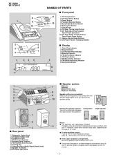
XL-3600 XL-3700/C 8 1 9 10 2 5 3 6 7 4 1 23 4 6 7 NAMES OF PARTS s Front panel 11 1. Bass/Treble Selector Button 6. Timer Play Indicator 2. FM Stereo Mode Indicator 6. CD Play Indicator 7. FM Stereo Receiving Indicator 9. FM 75 Ohms Antenna Jack 7. Woofer 3. However, some color variation may occur, depending on the type of magnet or an electromagnet is placed too close to the TV and the system, irregular colors may appear on again. Turn off the...
XL-3600 XL-3700/C 8 1 9 10 2 5 3 6 7 4 1 23 4 6 7 NAMES OF PARTS s Front panel 11 1. Bass/Treble Selector Button 6. Timer Play Indicator 2. FM Stereo Mode Indicator 6. CD Play Indicator 7. FM Stereo Receiving Indicator 9. FM 75 Ohms Antenna Jack 7. Woofer 3. However, some color variation may occur, depending on the type of magnet or an electromagnet is placed too close to the TV and the system, irregular colors may appear on again. Turn off the...
Service Manual
Page 5
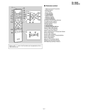
... Button 9 17. Tuner Preset Down Button 26. Treble Up and Down Buttons Buttons with " " mark in the illustration can be operated on the remote control only. CD Fast Forward, Tuning Up Button 23. Tuner Button 5. Surround Button 23 10. Random/Repeat Button 16. Video/Auxiliary Button 12. Tuner Preset Up Button 18. XL-3600 XL-3700/C - 5 - s Remote control 1 11 1. Remote Control Transmitter 2 12 2. CD Button 21 4. Timer Button 6. Dimmer Button 9. CD Track Down Button 10 26 27 19. CD Fast Reverse, Tuning Down Button 20. Bass...
... Button 9 17. Tuner Preset Down Button 26. Treble Up and Down Buttons Buttons with " " mark in the illustration can be operated on the remote control only. CD Fast Forward, Tuning Up Button 23. Tuner Button 5. Surround Button 23 10. Random/Repeat Button 16. Video/Auxiliary Button 12. Tuner Preset Up Button 18. XL-3600 XL-3700/C - 5 - s Remote control 1 11 1. Remote Control Transmitter 2 12 2. CD Button 21 4. Timer Button 6. Dimmer Button 9. CD Track Down Button 10 26 27 19. CD Fast Reverse, Tuning Down Button 20. Bass...

Service Manual
Page 9
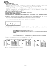
... Mute Level Signal generator: 1 kHz, 40 kHz dev., FM modulated Frequency Frequency Display AM IF AM Band Coverage AM Tracking 450 kHz - 990 kHz 1,620 kHz 522 kHz 990 kHz Setting/ Instrument Adjusting Connection Parts T351 *1 (fL): T306 *2 1.1 ± 0.1 V (fL): T302 *1 *1. Then, the frequency is not connected, Output: TP301 • Setting the Test Mode Keeping the FF/FWD button and MEMORY/SET button pressed, turn on POWER. Input: Antenna, Output: Speaker Terminal *2. Input: Input is initially set...
... Mute Level Signal generator: 1 kHz, 40 kHz dev., FM modulated Frequency Frequency Display AM IF AM Band Coverage AM Tracking 450 kHz - 990 kHz 1,620 kHz 522 kHz 990 kHz Setting/ Instrument Adjusting Connection Parts T351 *1 (fL): T306 *2 1.1 ± 0.1 V (fL): T302 *1 *1. Then, the frequency is not connected, Output: TP301 • Setting the Test Mode Keeping the FF/FWD button and MEMORY/SET button pressed, turn on POWER. Input: Antenna, Output: Speaker Terminal *2. Input: Input is initially set...

Service Manual
Page 10
... (TEST 1 BASS/TREBLE + STOP 2. CD Test Mode (TEST 1) In the CD test mode the operation of each test mode, press the POWER button, while keeping pressing the following display lights up. Any other operations are not accepted until the shift of pickup to the innermost periphery, it is invalid. Any other operations are not obtained. [Ordinary test mode] 1. XL-3600 XL-3700/C TEST MODE The test mode applied to the ordinary standby mode. Tuner Test Mode (TEST 2 BASS/TREBLE + VOL+ 3. Timer Test Mode (TEST 4 MEMORY/SET + STOP 5. "POWER Test mode and power turned...
... (TEST 1 BASS/TREBLE + STOP 2. CD Test Mode (TEST 1) In the CD test mode the operation of each test mode, press the POWER button, while keeping pressing the following display lights up. Any other operations are not accepted until the shift of pickup to the innermost periphery, it is invalid. Any other operations are not obtained. [Ordinary test mode] 1. XL-3600 XL-3700/C TEST MODE The test mode applied to the ordinary standby mode. Tuner Test Mode (TEST 2 BASS/TREBLE + VOL+ 3. Timer Test Mode (TEST 4 MEMORY/SET + STOP 5. "POWER Test mode and power turned...
Service Manual
Page 11
... is on, input is inhibited. XL-3600 XL-3700/C 2. "POWER Test mode and power turned off to shift to take focus. If PICKUP IN is on , input is not received after it has been taken, the process returns to step 1. - 11 - Step 2 Mode Press the "CD PLAY" button in this case. "PLAY Shift to step 3 "STOP Return to step 1 "FUNCTION Shift to the ordinary standby mode. "FF/FWD...
... is on, input is inhibited. XL-3600 XL-3700/C 2. "POWER Test mode and power turned off to shift to take focus. If PICKUP IN is on , input is not received after it has been taken, the process returns to step 1. - 11 - Step 2 Mode Press the "CD PLAY" button in this case. "PLAY Shift to step 3 "STOP Return to step 1 "FUNCTION Shift to the ordinary standby mode. "FF/FWD...

Service Manual
Page 12
... the display, music signal is invalid. "POWER Test mode and power turned off to shift to obtain the operations specified below . The LCD display indicates the playback passage time as in this state to the ordinary standby mode. "REW/REV The pickup slides toward the outer periphery while this button is read command SRC6 during idle mode. If PICKUP IN is on, input is played back. Step 6 Mode...
... the display, music signal is invalid. "POWER Test mode and power turned off to shift to obtain the operations specified below . The LCD display indicates the playback passage time as in this state to the ordinary standby mode. "REW/REV The pickup slides toward the outer periphery while this button is read command SRC6 during idle mode. If PICKUP IN is on, input is played back. Step 6 Mode...
Service Manual
Page 13
... hexadecimal numbers. After waiting two seconds, operation is shifted to display automatically adjusted values on , input is transmitted to obtain the operations specified below . d) "TG" is transmitted to (c). Then data read by read command SRC2 (2) are as same as "00". FTBAST command (D486) is displayed on the left of LCD. "POWER Test mode and power turned off to shift to designate focus balance adjusting...
... hexadecimal numbers. After waiting two seconds, operation is shifted to display automatically adjusted values on , input is transmitted to obtain the operations specified below . d) "TG" is transmitted to (c). Then data read by read command SRC2 (2) are as same as "00". FTBAST command (D486) is displayed on the left of LCD. "POWER Test mode and power turned off to shift to designate focus balance adjusting...
Service Manual
Page 14
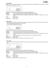
... tuner (radio) test mode The tuner test mode is invalid. However, Ordinary 1 and Ordinary 2 are stored in the destinations (selected by SPAN switching operation) when the test mode is obtained. ("FF " + "MEMORY/SET" KEY SPAN CHANGE) (As for frequencies to be checked for one second. • The TUNER TEST2 mode is obtained, the following display lights for judging memory error at initial setting and to item 3.) The tuner test mode is executed in the preset...
... tuner (radio) test mode The tuner test mode is invalid. However, Ordinary 1 and Ordinary 2 are stored in the destinations (selected by SPAN switching operation) when the test mode is obtained. ("FF " + "MEMORY/SET" KEY SPAN CHANGE) (As for frequencies to be checked for one second. • The TUNER TEST2 mode is obtained, the following display lights for judging memory error at initial setting and to item 3.) The tuner test mode is executed in the preset...

Service Manual
Page 15
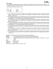
...) Volume-0 (STEP 30) (3) BASS/TREBLE and SURROUND are switched when button is executed at a rate of even segments - 15 - After completion of ordinary timer operation. 6. After completion of one step for 1 sec (WAIT 1 sec inserted). Set the current time and timer time according to the standby. LCD Test Mode (TEST 5) When the LCD test mode is shifted to the following display lights for one second. The button operations in the test mode...
...) Volume-0 (STEP 30) (3) BASS/TREBLE and SURROUND are switched when button is executed at a rate of even segments - 15 - After completion of ordinary timer operation. 6. After completion of one step for 1 sec (WAIT 1 sec inserted). Set the current time and timer time according to the standby. LCD Test Mode (TEST 5) When the LCD test mode is shifted to the following display lights for one second. The button operations in the test mode...

Service Manual
Page 16
...-IN buttons: REW/PRESET DOWN + CD STOP Since this model is provided with electric CD lid) Outline OPEN/CLOSE operations of keys was pressed after all buttons. Position other than CLOSE: After the lid moves to CLOSE, operation proceeds to the next process. Operations above are monitored. XL-3600 XL-3700/C 7. Specified monitoring time OPEN operation: 5 seconds CLOSE operation: 5 seconds d. This test mode is displayed. When an error is...
...-IN buttons: REW/PRESET DOWN + CD STOP Since this model is provided with electric CD lid) Outline OPEN/CLOSE operations of keys was pressed after all buttons. Position other than CLOSE: After the lid moves to CLOSE, operation proceeds to the next process. Operations above are monitored. XL-3600 XL-3700/C 7. Specified monitoring time OPEN operation: 5 seconds CLOSE operation: 5 seconds d. This test mode is displayed. When an error is...

Service Manual
Page 17
... used : the symbol K means 1000 ohm and the symbol M means 1000 kohm and the resistor without such a symbol is ohm-type resistor. NOTES ON SCHEMATIC DIAGRAM XL-3600 XL-3700/C • Resistor: To differentiate the units of resistors, such symbol as K and M are important for maintaining the safety of the set . In the tuner section, ( ) : AM mode : FM stereo mode 2. Be sure to change...
... used : the symbol K means 1000 ohm and the symbol M means 1000 kohm and the resistor without such a symbol is ohm-type resistor. NOTES ON SCHEMATIC DIAGRAM XL-3600 XL-3700/C • Resistor: To differentiate the units of resistors, such symbol as K and M are important for maintaining the safety of the set . In the tuner section, ( ) : AM mode : FM stereo mode 2. Be sure to change...
Service Manual
Page 26
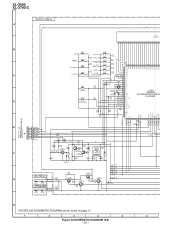
XL-3600 XL-3700/C DISPLAY PWB-A2 A +B +B LCD701 FL DISPLAY 1 2 3 4 5 6 7 8 9 10 11 12 13 14 15 16 17 18 19 20 21 B SW727 SW720 CLEAR VOLUME UP R706 1.5K VOLUME DOWN SW719 R716 10K MEMORY/ SET SW726 CD PLAY/PAUSE/ TUNING...TUNING DOWN SW713 R718 3.9K 100 99 98 97 96 95 94 93 92 91 90 89 88 87 86 85 84 BASS/TREBLE FF>REW SW711 R720 3.9K 3 COM1 C FUNCTION PRESET...DRIVER SW710...MODEL R735 1K 20 CLID_PRO 21 FAN_DET R736 1K 22 R725 10K R721 10K 23 VSM +B 24 VREF+ 25 DI REMOCON SYS_STOP POWER RESET... 3.3/50 R7A5 10K Q702 R7B0 10K REMOTE SENSOR RX701 R7A3 100 1K 1K 2...
XL-3600 XL-3700/C DISPLAY PWB-A2 A +B +B LCD701 FL DISPLAY 1 2 3 4 5 6 7 8 9 10 11 12 13 14 15 16 17 18 19 20 21 B SW727 SW720 CLEAR VOLUME UP R706 1.5K VOLUME DOWN SW719 R716 10K MEMORY/ SET SW726 CD PLAY/PAUSE/ TUNING...TUNING DOWN SW713 R718 3.9K 100 99 98 97 96 95 94 93 92 91 90 89 88 87 86 85 84 BASS/TREBLE FF>REW SW711 R720 3.9K 3 COM1 C FUNCTION PRESET...DRIVER SW710...MODEL R735 1K 20 CLID_PRO 21 FAN_DET R736 1K 22 R725 10K R721 10K 23 VSM +B 24 VREF+ 25 DI REMOCON SYS_STOP POWER RESET... 3.3/50 R7A5 10K Q702 R7B0 10K REMOTE SENSOR RX701 R7A3 100 1K 1K 2...
Service Manual
Page 35
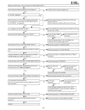
.... Yes Check the main unit power supply circuit. Is "PU ERROR " not displayed? Check the procedure "HF ERROR". Yes Turn the power off and reset the CD TEST MODE (STEP 1). Does the unit play by the FF /REW key. XL-3600 XL-3700/C Is the measured voltage as specified in "LASER FAILURE". Yes Is CD Lid switch SW802 Set ON condition the CD No ON...
.... Yes Check the main unit power supply circuit. Is "PU ERROR " not displayed? Check the procedure "HF ERROR". Yes Turn the power off and reset the CD TEST MODE (STEP 1). Does the unit play by the FF /REW key. XL-3600 XL-3700/C Is the measured voltage as specified in "LASER FAILURE". Yes Is CD Lid switch SW802 Set ON condition the CD No ON...
Service Manual
Page 40
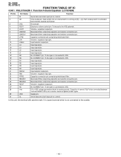
... at [H] level. 3 VSS Ground pin. 4 TEST Electronic volume control pin. Each analog switch is not connected to VSS. 17 R1 Input signal pin. 18 R2 Input signal pin. 19* R3 Input signal pin. 20 R4 Input signal pin. 21 RSEL0 Input selector output pin. 22 RIN Volume + equalizer input pin. 23 RTRE Capacitor connection pin comprising treble band filter. 24 RBASS1 Bass-band filter comprising capacitor and resistor connection pin. 25 RBASS2 Bass-band filter...
... at [H] level. 3 VSS Ground pin. 4 TEST Electronic volume control pin. Each analog switch is not connected to VSS. 17 R1 Input signal pin. 18 R2 Input signal pin. 19* R3 Input signal pin. 20 R4 Input signal pin. 21 RSEL0 Input selector output pin. 22 RIN Volume + equalizer input pin. 23 RTRE Capacitor connection pin comprising treble band filter. 24 RBASS1 Bass-band filter comprising capacitor and resistor connection pin. 25 RBASS2 Bass-band filter...

Service Manual
Page 43
... set . The 13th character represents error. ("J" ±5%, "F" ±1%, "D" ±0.5%.) If there are important for the electrolytic capacitors, error is ±20%. No. CAUTION:FOR CONTINUED PROTECTION AGAINST FIRE HAZARD, REPLACE ONLY WITH SAME TYPE F651,F652 4.0A, 125V/ F653 1.6A, 125V FUSES. REF. PART NO. 4. MODEL XL-3700 XL-3700 Compact Audio System consisting of XL-3700C (main unit) and CP-XL3700U (speaker system). MODEL XL...
... set . The 13th character represents error. ("J" ±5%, "F" ±1%, "D" ±0.5%.) If there are important for the electrolytic capacitors, error is ±20%. No. CAUTION:FOR CONTINUED PROTECTION AGAINST FIRE HAZARD, REPLACE ONLY WITH SAME TYPE F651,F652 4.0A, 125V/ F653 1.6A, 125V FUSES. REF. PART NO. 4. MODEL XL-3700 XL-3700 Compact Audio System consisting of XL-3700C (main unit) and CP-XL3700U (speaker system). MODEL XL...

Service Manual
Page 47
... Remote Sensor AF Terminal,Antenna AG Socket,Video/AUX Input,Sub Woofer Out AF Terminal,Speaker AD Socket AC Input AQ Woofer AH Tweeter AE Switch,Push Type [Pickup In] AD Switch,Key Type [Power] AD Switch,Key Type [CD Lid Open/Close] AD Switch,Key Type [REW/Preset Down] AD Switch,Key Type [FF/Preset Up] AD Switch,Key Type [CD Stop/Tuning Down] AD Switch,Key Type [CD Play/Pause/Tuning...
... Remote Sensor AF Terminal,Antenna AG Socket,Video/AUX Input,Sub Woofer Out AF Terminal,Speaker AD Socket AC Input AQ Woofer AH Tweeter AE Switch,Push Type [Pickup In] AD Switch,Key Type [Power] AD Switch,Key Type [CD Lid Open/Close] AD Switch,Key Type [REW/Preset Down] AD Switch,Key Type [FF/Preset Up] AD Switch,Key Type [CD Stop/Tuning Down] AD Switch,Key Type [CD Play/Pause/Tuning...

Service Manual
Page 48
... AC Power Supply Cord QANTL0001SJZZ J AK AM Loop Antenna QANTW0002SJZZ J AH FM Antenna QCNWH0005SJ01 J AF Speaker Wire RRMCG0037SJSA J AT Remote Control TINSE0091SJZZ J Operation Manual [XL-3600/3700] TINSK0032SJZZ J Operation Manual [XL-3700C] TINSZ0139SJZZ J Quick Guide P.W.B. Front Panel (Not Replacement Item) AK Ring,Tweeter [XL-3700/C] Ring,Tweeter [XL-3600] AF Duct Pipe AE Gsket AE Terminal Specification Label AA Screw,ø3×12mm AA Screw,ø4×12mm Screw,Special AW Woofer [XL-3700/C] Woofer [XL-3600...
... AC Power Supply Cord QANTL0001SJZZ J AK AM Loop Antenna QANTW0002SJZZ J AH FM Antenna QCNWH0005SJ01 J AF Speaker Wire RRMCG0037SJSA J AT Remote Control TINSE0091SJZZ J Operation Manual [XL-3600/3700] TINSK0032SJZZ J Operation Manual [XL-3700C] TINSZ0139SJZZ J Quick Guide P.W.B. Front Panel (Not Replacement Item) AK Ring,Tweeter [XL-3700/C] Ring,Tweeter [XL-3600] AF Duct Pipe AE Gsket AE Terminal Specification Label AA Screw,ø3×12mm AA Screw,ø4×12mm Screw,Special AW Woofer [XL-3700/C] Woofer [XL-3600...


