
XV-Z2000U Operation Manual
Page 2
Model No.: XV-Z2000 Serial No.: There are designed to Part 15 of light, or view directly. ONLY WARNING: High brightness light source. REFER SERVICING TO QUALIFIED SERVICE PERSONNEL. ... any unauthorized changes or modifications to this operation manual carefully. U.S.A. ONLY -1 See bottom of the projector and retain this information. NO USER-SERVICEABLE PARTS EXCEPT LAMP UNIT. U.S.A. However, there is to your new SHARP Projector, using the projector, please read this equipment not expressly approved by the manufacturer could void the user's authority to...
Model No.: XV-Z2000 Serial No.: There are designed to Part 15 of light, or view directly. ONLY WARNING: High brightness light source. REFER SERVICING TO QUALIFIED SERVICE PERSONNEL. ... any unauthorized changes or modifications to this operation manual carefully. U.S.A. ONLY -1 See bottom of the projector and retain this information. NO USER-SERVICEABLE PARTS EXCEPT LAMP UNIT. U.S.A. However, there is to your new SHARP Projector, using the projector, please read this equipment not expressly approved by the manufacturer could void the user's authority to...
XV-Z2000U Operation Manual
Page 3
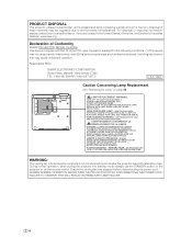
...interference received, including interference that may be regulated due to run for about 90 seconds after the projector enters the standby mode. Declaration of Conformity SHARP PROJECTOR, MODEL XV-Z2000 This device complies with Part 15 of America, the Electronic Industries Alliance: www.eiae.org .... HOT SURFACE INSIDE. ALLOW 1 HOUR TO COOL BEFORE REPLACING THE LAMP. REPLACE WITH SAME SHARP LAMP UNIT MODEL AN-K2LP ...
...interference received, including interference that may be regulated due to run for about 90 seconds after the projector enters the standby mode. Declaration of Conformity SHARP PROJECTOR, MODEL XV-Z2000 This device complies with Part 15 of America, the Electronic Industries Alliance: www.eiae.org .... HOT SURFACE INSIDE. ALLOW 1 HOUR TO COOL BEFORE REPLACING THE LAMP. REPLACE WITH SAME SHARP LAMP UNIT MODEL AN-K2LP ...
XV-Z2000U Operation Manual
Page 4
... has some inactive pixels within acceptable tolerances which may not copy, modify, adapt, translate, distribute, reverse engineer, reverse assemble or discompile the contents thereof. This SHARP projector uses a DMD panel. This very sophisticated panel contains 921,600 pixels micromirrors. Introduction WARNING: Some IC chips in inactive dots on the picture screen.
... has some inactive pixels within acceptable tolerances which may not copy, modify, adapt, translate, distribute, reverse engineer, reverse assemble or discompile the contents thereof. This SHARP projector uses a DMD panel. This very sophisticated panel contains 921,600 pixels micromirrors. Introduction WARNING: Some IC chips in inactive dots on the picture screen.
XV-Z2000U Operation Manual
Page 5
... 19 INPUT Terminals and Connectable Main Equipment 19 Samples of Cables for Connection 20 Connecting to Video Equipment 21 Connecting to a Computer 25 Controlling the Projector by a Computer ... 27 Gamma Correction Function 43 Emphasising the Contrast 43 Picture Mode Function 44 Switching the High Brightness/High Contrast Mode 44 Computer Image... On-screen Display Language ..... 52 Setting the Projection Mode 52 Communication conditions 60 Basic format 60 Commands 60 Computer Compatibility Chart 61 Troubleshooting 62 For SHARP Assistance (U.S.A.
... 19 INPUT Terminals and Connectable Main Equipment 19 Samples of Cables for Connection 20 Connecting to Video Equipment 21 Connecting to a Computer 25 Controlling the Projector by a Computer ... 27 Gamma Correction Function 43 Emphasising the Contrast 43 Picture Mode Function 44 Switching the High Brightness/High Contrast Mode 44 Computer Image... On-screen Display Language ..... 52 Setting the Projection Mode 52 Communication conditions 60 Basic format 60 Commands 60 Computer Compatibility Chart 61 Troubleshooting 62 For SHARP Assistance (U.S.A.

XV-Z2000U Operation Manual
Page 6
... your nearest Authorized SharpVision Service Center or Dealer. Marks Used in This Operation Manual Info ........Indicates safeguards when using the projector. Note ........Indicates additional information for setting up and operating the projector. • In this operation manual, the illustration and the screen display are simplified for explanation, and may not be available...
... your nearest Authorized SharpVision Service Center or Dealer. Marks Used in This Operation Manual Info ........Indicates safeguards when using the projector. Note ........Indicates additional information for setting up and operating the projector. • In this operation manual, the illustration and the screen display are simplified for explanation, and may not be available...
XV-Z2000U Operation Manual
Page 8
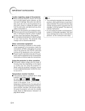
... Rest your nearest Authorized SharpVision Service Center or Dealer for long hours will not reduce the overall operation life of the lens. Place the projector where the intake and exhaust vents are not obstructed. ■ If the cooling fan becomes obstructed, a protection circuit will return the... and dim the lights when setting up the screen in a high posi- Avoid locations with the lens so as the projector is subjected to maintain high image quality, SHARP recommends that the intake vent and the exhaust vent are not blocked, plug the power cord back in places exposed to ...
... Rest your nearest Authorized SharpVision Service Center or Dealer for long hours will not reduce the overall operation life of the lens. Place the projector where the intake and exhaust vents are not obstructed. ■ If the cooling fan becomes obstructed, a protection circuit will return the... and dim the lights when setting up the screen in a high posi- Avoid locations with the lens so as the projector is subjected to maintain high image quality, SHARP recommends that the intake vent and the exhaust vent are not blocked, plug the power cord back in places exposed to ...
XV-Z2000U Operation Manual
Page 9
...power supply voltage and the shape of the plug may vary depending on how to make the connections AFTER unplugging the power cord of the projector from the wall outlet, and disconnect any other audio- Take extra care with the lens. Other connected equipment ■ When connecting a ... or other cables connected to it to hard impact and/or vibration, as the cooling fan also stops. -8 Temperature monitor function ■ If the projector starts to overheat due to setup problems or blockage of the air vents, " " and " " will enter the standby mode. This can cause ...
...power supply voltage and the shape of the plug may vary depending on how to make the connections AFTER unplugging the power cord of the projector from the wall outlet, and disconnect any other audio- Take extra care with the lens. Other connected equipment ■ When connecting a ... or other cables connected to it to hard impact and/or vibration, as the cooling fan also stops. -8 Temperature monitor function ■ If the projector starts to overheat due to setup problems or blockage of the air vents, " " and " " will enter the standby mode. This can cause ...
XV-Z2000U Operation Manual
Page 10
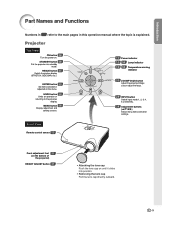
... to the main pages in refer to the previous display. Front View Remote control sensor 13 Front adjustment foot 31 (on the bottom of the projector) HEIGHT ADJUST button 31 • Attaching the lens cap Push the lens cap on until it clicks into standby mode.... Projector Top View ON button 28 Turn the power on the menu. STANDBY button 28 Put the projector into position. • Removing the lens cap Pull the lens cap directly outward. -9 MENU button 38 Display...
... to the main pages in refer to the previous display. Front View Remote control sensor 13 Front adjustment foot 31 (on the bottom of the projector) HEIGHT ADJUST button 31 • Attaching the lens cap Push the lens cap on until it clicks into standby mode.... Projector Top View ON button 28 Turn the power on the menu. STANDBY button 28 Put the projector into position. • Removing the lens cap Pull the lens cap directly outward. -9 MENU button 38 Display...

XV-Z2000U Operation Manual
Page 11
The lamp is abnormally high. (See page 54.) -10 Normal (Standby) Green on ... Normal Green blinks ... Normal Red on ... Normal (Power on) Lamp indicator Green on ... Red on ... The internal temperature is warming up or shutting down abnormally or needs to be changed. (See page 54.) Temperature warning indicator Off ... The lamp has been shut down . Part Names and Functions About the Indicators on the Projector Power indicator Red on ...
The lamp is abnormally high. (See page 54.) -10 Normal (Standby) Green on ... Normal Green blinks ... Normal Red on ... Normal (Power on) Lamp indicator Green on ... Red on ... The internal temperature is warming up or shutting down abnormally or needs to be changed. (See page 54.) Temperature warning indicator Off ... The lamp has been shut down . Part Names and Functions About the Indicators on the Projector Power indicator Red on ...

XV-Z2000U Operation Manual
Page 12
... to the information that came with the system for use it to secure the projector. -11 Using the Kensington Lock • This projector has a Kensington Security Standard connector for instructions on page 19. Projector (Rear View) Terminals Refer to "INPUT Terminals and Connectable Main Equipment" on how... to use with an S-video terminal. 27 RS-232C terminal Control the projector using a computer. This is explained. INPUT 2 terminal 21 Component signals. Digital input type switch 22 23 25 26 INPUT 5/DIGITAL ...
... to the information that came with the system for use it to secure the projector. -11 Using the Kensington Lock • This projector has a Kensington Security Standard connector for instructions on page 19. Projector (Rear View) Terminals Refer to "INPUT Terminals and Connectable Main Equipment" on how... to use with an S-video terminal. 27 RS-232C terminal Control the projector using a computer. This is explained. INPUT 2 terminal 21 Component signals. Digital input type switch 22 23 25 26 INPUT 5/DIGITAL ...
XV-Z2000U Operation Manual
Page 13
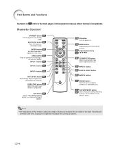
... 29 INPUT 2 button 29 INPUT 4 button 29 AUTO SYNC button 46 Automatically adjust images when connected to a computer. Remote Control STANDBY button 28 Put the projector into standby mode. Note • All the buttons on the remote control are made of luminous material that is explained. Part Names and Functions Numbers...
... 29 INPUT 2 button 29 INPUT 4 button 29 AUTO SYNC button 46 Automatically adjust images when connected to a computer. Remote Control STANDBY button 28 Put the projector into standby mode. Note • All the buttons on the remote control are made of luminous material that is explained. Part Names and Functions Numbers...

XV-Z2000U Operation Manual
Page 14
...Do not mix new and old batteries. Please follow the precautions below. Ensure to replace them as soon as leaving them to control the projector within the ranges shown in place. Battery fluid from the remote control once they have different properties, therefore do not mix batteries of new ...wipe them and then remove them to moisture or high temperature. • The remote control may differ depending on the screen material. In this projector may cause them using the remote control: • Ensure not to drop, expose to leak or explode. Note • The signal from ...
...Do not mix new and old batteries. Please follow the precautions below. Ensure to replace them as soon as leaving them to control the projector within the ranges shown in place. Battery fluid from the remote control once they have different properties, therefore do not mix batteries of new ...wipe them and then remove them to moisture or high temperature. • The remote control may differ depending on the screen material. In this projector may cause them using the remote control: • Ensure not to drop, expose to leak or explode. Note • The signal from ...

XV-Z2000U Operation Manual
Page 15
... buttons ('/"/\/|) 6 ZOOM/FOCUS button 4 INPUT buttons, DIGITAL INPUT button 6 HEIGHT ADJUST button 1. Place the projector facing a screen Page 16 2. Remove the lens cap and turn the projector on On the projector On the remote control Page 28 -14 Pages 21-28 3. Quick Start This section shows the basic operation... and Projection Connection of the audio equipment using an audio cable. Connect the projector to the video equipment and plug the power cord into the AC socket of the projector Connect the audio output terminal of the video equipment to the audio input terminal...
... buttons ('/"/\/|) 6 ZOOM/FOCUS button 4 INPUT buttons, DIGITAL INPUT button 6 HEIGHT ADJUST button 1. Place the projector facing a screen Page 16 2. Remove the lens cap and turn the projector on On the projector On the remote control Page 28 -14 Pages 21-28 3. Quick Start This section shows the basic operation... and Projection Connection of the audio equipment using an audio cable. Connect the projector to the video equipment and plug the power cord into the AC socket of the projector Connect the audio output terminal of the video equipment to the audio input terminal...
XV-Z2000U Operation Manual
Page 16
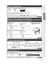
... |. 2 Adjust the focus by pressing \ or |. 2 Adjust the projected image size by pressing ' or ". 7. Quick Start 4. Page 29 5. On the projector On the remote control 1 Press . 1 Press . 2 Adjust the zoom by pressing ' or ". 2 Adjust the zoom by adjusting zoom. On the...is displayed, to switch the INPUT mode. Turn the video equipment on the remote control. On the remote control 1 Press . 3 Adjust the projector angle using the Keystone Correction On the remote control Horizontal HEIGHT ADJUST button Pages 30, 31 Vertical Select "H Keystone" Adjust or "V Keystone". ...
... |. 2 Adjust the focus by pressing \ or |. 2 Adjust the projected image size by pressing ' or ". 7. Quick Start 4. Page 29 5. On the projector On the remote control 1 Press . 1 Press . 2 Adjust the zoom by pressing ' or ". 2 Adjust the zoom by adjusting zoom. On the...is displayed, to switch the INPUT mode. Turn the video equipment on the remote control. On the remote control 1 Press . 3 Adjust the projector angle using the Keystone Correction On the remote control Horizontal HEIGHT ADJUST button Pages 30, 31 Vertical Select "H Keystone" Adjust or "V Keystone". ...
XV-Z2000U Operation Manual
Page 17
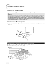
... the screen so that it is not in a sunny or bright room. Note • The projector lens should be distorted, making viewing difficult. Standard Setup (Front Projection) ■ Place the projector at the required distance from the screen according to the desired picture size. (See page 17.) Indication... line passing through the lens center is not perpendicular to achieve an optimal image. Close the curtains and dim the lights when setting up the projector in direct sunlight or room light. Example : When using a wide screen (16:9) Picture Size 200" 150" 100" 80" 60" 174" × 98" ...
... the screen so that it is not in a sunny or bright room. Note • The projector lens should be distorted, making viewing difficult. Standard Setup (Front Projection) ■ Place the projector at the required distance from the screen according to the desired picture size. (See page 17.) Indication... line passing through the lens center is not perpendicular to achieve an optimal image. Close the curtains and dim the lights when setting up the projector in direct sunlight or room light. Example : When using a wide screen (16:9) Picture Size 200" 150" 100" 80" 60" 174" × 98" ...

XV-Z2000U Operation Manual
Page 18
...) = 0.03810r / 2.54 H (cm) = 0.03810r Note • There may be an error of ± 3% in the above values. -17 Install the projector so that projected images are projected onto the screen at the optimum size by referring to the lens center (in/cm) The formula for picture.../ 0.3048 L1 (m) = 0.02671r-0.05334 L2 (ft) = (0.03999r-0.05215) / 0.3048 L2 (m) = 0.03999r-0.05215 H (in the table as a reference when installing the projector. Side View Screen H Lens center L When using a normal screen (4:3): In case of setting the 16:9 picture to the screen. Use the values in ) = 0.04151r / ...
...) = 0.03810r / 2.54 H (cm) = 0.03810r Note • There may be an error of ± 3% in the above values. -17 Install the projector so that projected images are projected onto the screen at the optimum size by referring to the lens center (in/cm) The formula for picture.../ 0.3048 L1 (m) = 0.02671r-0.05334 L2 (ft) = (0.03999r-0.05215) / 0.3048 L2 (m) = 0.03999r-0.05215 H (in the table as a reference when installing the projector. Side View Screen H Lens center L When using a normal screen (4:3): In case of setting the 16:9 picture to the screen. Use the values in ) = 0.04151r / ...

XV-Z2000U Operation Manual
Page 19
... for use the optional Sharp ceiling-mount bracket for AN-CM270.) ■ Invert the image by setting "Ceiling + Front" in the "PRJ Mode" menu. (See page 52.) ■ When the mirror is recommended that you use of the audience. Setting Up the Projector Projecting a Reversed Image ...CM270 ceiling-mount bracket, AN-EP101B extension tube for this installation. ■ Before mounting the projector, contact your nearest Authorized SharpVision Service Center or Dealer to carefully position both the projector and the mirror so the light does not shine into the eyes of this function. -18 ...
... for use the optional Sharp ceiling-mount bracket for AN-CM270.) ■ Invert the image by setting "Ceiling + Front" in the "PRJ Mode" menu. (See page 52.) ■ When the mirror is recommended that you use of the audience. Setting Up the Projector Projecting a Reversed Image ...CM270 ceiling-mount bracket, AN-EP101B extension tube for this installation. ■ Before mounting the projector, contact your nearest Authorized SharpVision Service Center or Dealer to carefully position both the projector and the mirror so the light does not shine into the eyes of this function. -18 ...

XV-Z2000U Operation Manual
Page 20
....). (See page 24.) Connections INPUT 4 terminal Connecting video equipment without S-video output terminal. (See page 24.) RS-232C terminal Connecting the computer to control the projector. (See page 27.) -19
....). (See page 24.) Connections INPUT 4 terminal Connecting video equipment without S-video output terminal. (See page 24.) RS-232C terminal Connecting the computer to control the projector. (See page 27.) -19

XV-Z2000U Operation Manual
Page 21
Equipment Audio-visual equipment Terminal on connected equipment Cable Component video output terminal Component cable (commercially available) Terminal on the projector INPUT 1, 2 Terminal for using the dedicated cable Dedicated cable attached to the connected equipment. DVI output terminal DVI cable (sold separately: AN-C3DV) INPUT 1, 2 INPUT 5/...
Equipment Audio-visual equipment Terminal on connected equipment Cable Component video output terminal Component cable (commercially available) Terminal on the projector INPUT 1, 2 Terminal for using the dedicated cable Dedicated cable attached to the connected equipment. DVI output terminal DVI cable (sold separately: AN-C3DV) INPUT 1, 2 INPUT 5/...
XV-Z2000U Operation Manual
Page 22
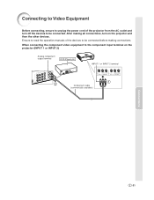
..., turn off the devices to be connected before making connections. Ensure to read the operation manuals of the projector from the AC outlet and turn on the projector (INPUT 1 or INPUT 2) Analog component output terminal DVD Player,etc. When connecting the component video equipment ...to the component input terminal on the projector and then the other devices. INPUT 1 or INPUT 2 terminal 2 Component cable 1 (commercially available) Connections -21 Connecting to Video ...
..., turn off the devices to be connected before making connections. Ensure to read the operation manuals of the projector from the AC outlet and turn on the projector (INPUT 1 or INPUT 2) Analog component output terminal DVD Player,etc. When connecting the component video equipment ...to the component input terminal on the projector and then the other devices. INPUT 1 or INPUT 2 terminal 2 Component cable 1 (commercially available) Connections -21 Connecting to Video ...


