
Operation Manual
Page 2
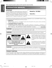
... of important operating and maintenance (servicing) instructions in reporting the loss or theft of light. DO NOT REMOVE SCREWS EXCEPT SPECIFIED USER SERVICE SCREWS. NO USER-SERVICEABLE PARTS EXCEPT LAMP UNIT. The lightning flash with the projector. 1. The exclamation point within the product's enclosure that you have checked the contents of the carton thoroughly against the list of "Supplied Accessories" on the bottom of your new SHARP Projector, using the projector, please...
... of important operating and maintenance (servicing) instructions in reporting the loss or theft of light. DO NOT REMOVE SCREWS EXCEPT SPECIFIED USER SERVICE SCREWS. NO USER-SERVICEABLE PARTS EXCEPT LAMP UNIT. The lightning flash with the projector. 1. The exclamation point within the product's enclosure that you have checked the contents of the carton thoroughly against the list of "Supplied Accessories" on the bottom of your new SHARP Projector, using the projector, please...
Operation Manual
Page 3
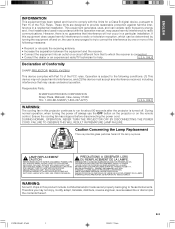
... in a particular installation. Ensure the cooling fan has stopped before disconnecting the power cord. LAMP REPLACEMENT CAUTION BEFORE REMOVING THE SCREW, DISCONNECT POWER CORD. TURN OFF LAMP BEFORE SERVICING. A MANIPULER AVEC PRECAUTION, SE REPORTER AU MODE D'EMPLOI. ONLY WARNING: The cooling fan in accordance with Part 15 of Conformity SHARP PROJECTOR, MODEL XV-Z90U This device complies with the operation manual, may cause undesired operation. ALLOW 1 HOUR TO COOL BEFORE REPLACING THE LAMP. MEDIUM PRESSURE LAMP : RISK OF...
... in a particular installation. Ensure the cooling fan has stopped before disconnecting the power cord. LAMP REPLACEMENT CAUTION BEFORE REMOVING THE SCREW, DISCONNECT POWER CORD. TURN OFF LAMP BEFORE SERVICING. A MANIPULER AVEC PRECAUTION, SE REPORTER AU MODE D'EMPLOI. ONLY WARNING: The cooling fan in accordance with Part 15 of Conformity SHARP PROJECTOR, MODEL XV-Z90U This device complies with the operation manual, may cause undesired operation. ALLOW 1 HOUR TO COOL BEFORE REPLACING THE LAMP. MEDIUM PRESSURE LAMP : RISK OF...
Operation Manual
Page 4
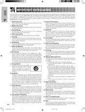
... disconnect the power cord. Grounding or Polarization This product is a safety feature. Do not defeat the safety purpose of power source indicated on the product. 17. Refer all servicing to rain or water. Wall or Ceiling Mounting This product should be moved with a three-wire grounding-type plug, a plug having a third (grounding) pin. Use a damp cloth for its installation, use instructions should...
... disconnect the power cord. Grounding or Polarization This product is a safety feature. Do not defeat the safety purpose of power source indicated on the product. 17. Refer all servicing to rain or water. Wall or Ceiling Mounting This product should be moved with a three-wire grounding-type plug, a plug having a third (grounding) pin. Use a damp cloth for its installation, use instructions should...
Operation Manual
Page 5
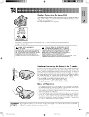
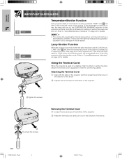
... will automatically turn on Operation • The exhaust ventilative hole, the lamp cage cover and adjacent areas may get extremely hot during projector operation. Remove the projector power cord from humidity, dust and cigarette smoke. WARNING: High brightness light source. ALLOW 1 HOUR TO COOL BEFORE REPLACING THE LAMP. Important Information IMPORTANT SAFEGUARDS Caution Concerning the Lamp Unit There is subjected to these environments, the lens and part of filter must be...
... will automatically turn on Operation • The exhaust ventilative hole, the lamp cage cover and adjacent areas may get extremely hot during projector operation. Remove the projector power cord from humidity, dust and cigarette smoke. WARNING: High brightness light source. ALLOW 1 HOUR TO COOL BEFORE REPLACING THE LAMP. Important Information IMPORTANT SAFEGUARDS Caution Concerning the Lamp Unit There is subjected to these environments, the lens and part of filter must be...
Operation Manual
Page 6
... used for 2,500 hours, the projector power will automatically turn off period the power will enter standby mode. Refer to replace the lamp. Refer to "Lamp/Maintenance Indicators" on page 44 for 2,400 hours, "LAMP" and " " will blink in the lower-left corner of the picture to advise you to "Lamp/Maintenance Indicators" on a desktop, high mounted or ceiling mounted, attach the terminal cover (supplied) to hide the connecting cables. Using the Terminal Cover When the projector is automatically controlled...
... used for 2,500 hours, the projector power will automatically turn off period the power will enter standby mode. Refer to replace the lamp. Refer to "Lamp/Maintenance Indicators" on page 44 for 2,400 hours, "LAMP" and " " will blink in the lower-left corner of the picture to advise you to "Lamp/Maintenance Indicators" on a desktop, high mounted or ceiling mounted, attach the terminal cover (supplied) to hide the connecting cables. Using the Terminal Cover When the projector is automatically controlled...
Operation Manual
Page 7
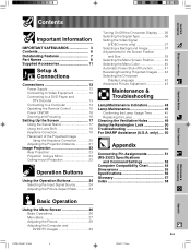
... 13 Connecting to a Computer 14 Operating the Remote Control 15 Power ON/OFF 16 Zooming and Focusing 16 Setting Up the Screen 17 Using the Swivel Stand 17 Using the Lens Shift 18 Keystone Correction 19 Placement of the Projected Image Using the Keystone Correction 20 Adjusting the Projection Distance 21 Image Projection 23 Rear Projection 23 Projection Using a Mirror 23 Ceiling-mount Projection 23 Operation Buttons Using the Operation Buttons 24 Selecting the Input Signal Source 24 Adjusting the Picture Aspect Ratio 24 Turning On/Off the On-screen Display...
... 13 Connecting to a Computer 14 Operating the Remote Control 15 Power ON/OFF 16 Zooming and Focusing 16 Setting Up the Screen 17 Using the Swivel Stand 17 Using the Lens Shift 18 Keystone Correction 19 Placement of the Projected Image Using the Keystone Correction 20 Adjusting the Projection Distance 21 Image Projection 23 Rear Projection 23 Projection Using a Mirror 23 Ceiling-mount Projection 23 Operation Buttons Using the Operation Buttons 24 Selecting the Input Signal Source 24 Adjusting the Picture Aspect Ratio 24 Turning On/Off the On-screen Display...
Operation Manual
Page 8
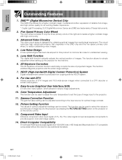
... keystone correction function electrically corrects the size of DTV images and 16:9 wide-screen images when connected to the input source for undisturbed viewing. 5. Easy-to minimize fan noise for optimal image contrast. 12. The function can be used to adjust the color temperature to suit the type of image input to the projector. 11. DMD™* (Digital Micromirror Device) Chip The DMD Chip allows for any additional hardware. Five Speed Primary Color Wheel The color wheel...
... keystone correction function electrically corrects the size of DTV images and 16:9 wide-screen images when connected to the input source for undisturbed viewing. 5. Easy-to minimize fan noise for optimal image contrast. 12. The function can be used to adjust the color temperature to suit the type of image input to the projector. 11. DMD™* (Digital Micromirror Device) Chip The DMD Chip allows for any additional hardware. Five Speed Primary Color Wheel The color wheel...
Operation Manual
Page 9
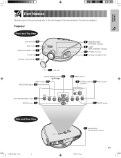
Important Information Part Names Numbers next to the part names refer to the main pages in this manual where the topic is explained. Projector Front and Top View Lens shift dial 18 Zoom knob 16 Exhaust ventilative hole 4 Focus ring 16 Remote control sensor 15 5 TEMPERATURE WARNING indicator 5 LAMP REPLACEMENT indicator 16 POWER indicator 4 Exhaust ventilative hole 9 Lens cap ADJUSTMENT buttons 19 UNDO button 26 KEYSTONE button 19 26 MENU button 16 POWER buttons 24 INPUT button (ON/OFF) PICTURE SETTING button 32 ENTER button 19...
Important Information Part Names Numbers next to the part names refer to the main pages in this manual where the topic is explained. Projector Front and Top View Lens shift dial 18 Zoom knob 16 Exhaust ventilative hole 4 Focus ring 16 Remote control sensor 15 5 TEMPERATURE WARNING indicator 5 LAMP REPLACEMENT indicator 16 POWER indicator 4 Exhaust ventilative hole 9 Lens cap ADJUSTMENT buttons 19 UNDO button 26 KEYSTONE button 19 26 MENU button 16 POWER buttons 24 INPUT button (ON/OFF) PICTURE SETTING button 32 ENTER button 19...
Operation Manual
Page 16
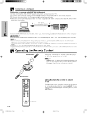
... control the projector within the range shown on the left. • The signal from the computer while it is not correctly set up. However, the effective distance of the operation buttons can be reflected off , before switching the "DIGITAL INPUT TYPE" swich and connecting. 3 DVI cable (commercially available) 2 1 Connect an RS-232C cable (null modem, cross type, commercially available) to the serial port on the computer. LIGHT button...
... control the projector within the range shown on the left. • The signal from the computer while it is not correctly set up. However, the effective distance of the operation buttons can be reflected off , before switching the "DIGITAL INPUT TYPE" swich and connecting. 3 DVI cable (commercially available) 2 1 Connect an RS-232C cable (null modem, cross type, commercially available) to the serial port on the computer. LIGHT button...
Operation Manual
Page 17
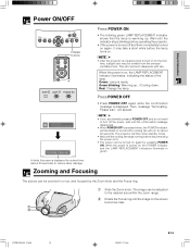
... turned on for a short time (about 90 seconds. Then, message "Terminating. The image can be adjusted to reduce lamp damage. Wait until the image on , the LAMP REPLACEMENT indicator illuminates, indicating the status of the lamp. Setup & Connections Power ON/OFF POWER buttons TEMP. Green: Lamp is displayed. Please wait." LAMP POWER Press POWER ON. • The blinking green LAMP REPLACEMENT indicator shows that the lamp is displayed for the first time, a slight odor may be zoomed in green. This odor will soon disappear with use. Red: Change...
... turned on for a short time (about 90 seconds. Then, message "Terminating. The image can be adjusted to reduce lamp damage. Wait until the image on , the LAMP REPLACEMENT indicator illuminates, indicating the status of the lamp. Setup & Connections Power ON/OFF POWER buttons TEMP. Green: Lamp is displayed. Please wait." LAMP POWER Press POWER ON. • The blinking green LAMP REPLACEMENT indicator shows that the lamp is displayed for the first time, a slight odor may be zoomed in green. This odor will soon disappear with use. Red: Change...
Operation Manual
Page 22
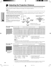
... x distance from the lens center to the lower edge of the screen (feet) E-21 • There is an error of ± 3% in the formula above .) When using a wide screen (16:9) 16 9 : Picture area : Area covered by Keystone correction v C. Standard Setup (Front Projection) Center of horizontal and vertical values may be distorted, making viewing difficult. B'. 0.15y B. 0.1y A. Setup & Connections Adjusting the Projection Distance Position the projector perpendicular to the screen...
... x distance from the lens center to the lower edge of the screen (feet) E-21 • There is an error of ± 3% in the formula above .) When using a wide screen (16:9) 16 9 : Picture area : Area covered by Keystone correction v C. Standard Setup (Front Projection) Center of horizontal and vertical values may be distorted, making viewing difficult. B'. 0.15y B. 0.1y A. Setup & Connections Adjusting the Projection Distance Position the projector perpendicular to the screen...

Operation Manual
Page 45
... used for example during a brief rest, the LAMP REPLACEMENT indicator may be triggered, preventing the power from the wall outlet and plug it back in red. over 2,400 hours. Problem • Blocked air intake. • Clogged ventilative hole. • Cooling fan breakdown. • Internal circuit failure. light up , follow the procedures given below. After turning off and then turned on . Lamp/Maintenance Indicators Maintenance Indicators TEMP. LAMP POWER TEMPERATURE LAMP WARNING REPLACEMENT indicator indicator POWER indicator • The warning lights...
... used for example during a brief rest, the LAMP REPLACEMENT indicator may be triggered, preventing the power from the wall outlet and plug it back in red. over 2,400 hours. Problem • Blocked air intake. • Clogged ventilative hole. • Cooling fan breakdown. • Internal circuit failure. light up , follow the procedures given below. After turning off and then turned on . Lamp/Maintenance Indicators Maintenance Indicators TEMP. LAMP POWER TEMPERATURE LAMP WARNING REPLACEMENT indicator indicator POWER indicator • The warning lights...
Operation Manual
Page 46
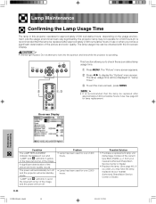
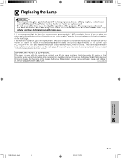
...-screen Display Maintenance & Troubleshooting Condition The LAMP REPLACEMENT indicator illuminates in red, and "LAMP" and " " will be displayed in "Lamp Timer". 3 To exit the menu screen, press MENU. • It is recommended that the lamp be replaced after approximately 2,400 cumulative hours of use or when you notice a significant deterioration of use . Problem • Lamp has been used for over 2,400 hours. • Lamp has been used for lamp replacement. Lamp Maintenance Confirming the Lamp Usage Time The lamp in this projector operates...
...-screen Display Maintenance & Troubleshooting Condition The LAMP REPLACEMENT indicator illuminates in red, and "LAMP" and " " will be displayed in "Lamp Timer". 3 To exit the menu screen, press MENU. • It is recommended that the lamp be replaced after approximately 2,400 cumulative hours of use or when you notice a significant deterioration of use . Problem • Lamp has been used for over 2,400 hours. • Lamp has been used for lamp replacement. Lamp Maintenance Confirming the Lamp Usage Time The lamp in this projector operates...
Operation Manual
Page 47
... 2,400 cumulative hours of use or when you may be extremely hot. CUSTOMERS: The lamp included with this projector under warranty, including lamp replacement, must be replaced after the power cord is potential glass particles hazard if the lamp ruptures. U.S.A. ONLY Maintenance & Troubleshooting XVZ90U(E)#p45_46.p65 46 02.8.20, 7:57 PM E-46 Then carefully change the lamp by a 90-day parts and labor limited...
... 2,400 cumulative hours of use or when you may be extremely hot. CUSTOMERS: The lamp included with this projector under warranty, including lamp replacement, must be replaced after the power cord is potential glass particles hazard if the lamp ruptures. U.S.A. ONLY Maintenance & Troubleshooting XVZ90U(E)#p45_46.p65 46 02.8.20, 7:57 PM E-46 Then carefully change the lamp by a 90-day parts and labor limited...
Operation Manual
Page 48
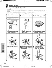
... until the cooling fan stops running. 4 5 Loosen the user service screw that secures the Slide the lamp cage cover in the direction lamp cage cover. User service screws 7 8 9 Remove the lamp cage. of the projector. • To avoid injury to yourself and damage to the lamp, carefully follow the steps below. • Replace the lamp after turning off the power and unplugging the power cord. 1 Turn off the power. 2 3 Unplug the power cord. Remove the Swivel...
... until the cooling fan stops running. 4 5 Loosen the user service screw that secures the Slide the lamp cage cover in the direction lamp cage cover. User service screws 7 8 9 Remove the lamp cage. of the projector. • To avoid injury to yourself and damage to the lamp, carefully follow the steps below. • Replace the lamp after turning off the power and unplugging the power cord. 1 Turn off the power. 2 3 Unplug the power cord. Remove the Swivel...
Operation Manual
Page 51
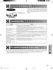
... 36.) For SHARP Assistance (U.S.A. Troubleshooting Problem No picture appears. changes. Using the Kensington Lock Rear View Kensington Security Standard connector This projector has a Kensington Security Standard connector for use with the system for instructions on how to use it to secure the projector. Image is pink (no green) on INPUT 2 Component. Check • Projector power cord is not plugged into the wall outlet. • Selected input is due to "Lamp/Maintenance Indicators" on...
... 36.) For SHARP Assistance (U.S.A. Troubleshooting Problem No picture appears. changes. Using the Kensington Lock Rear View Kensington Security Standard connector This projector has a Kensington Security Standard connector for use with the system for instructions on how to use it to secure the projector. Image is pink (no green) on INPUT 2 Component. Check • Projector power cord is not plugged into the wall outlet. • Selected input is due to "Lamp/Maintenance Indicators" on...
Operation Manual
Page 53
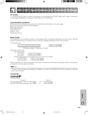
... page 14 for connection.) Communication conditions Set the serial port settings of the computer to match those of the projector, the projector operating status cannot be used to control the projector by transmitting the display commands for the previous command from the projector is being sent, send each command only after the OK response code for each adjustment menu and checking the status with the On-screen Display. Computer P OWR _ _ _ 1 → ← Projector OK Appendix...
... page 14 for connection.) Communication conditions Set the serial port settings of the computer to match those of the projector, the projector operating status cannot be used to control the projector by transmitting the display commands for the previous command from the projector is being sent, send each command only after the OK response code for each adjustment menu and checking the status with the On-screen Display. Computer P OWR _ _ _ 1 → ← Projector OK Appendix...
Operation Manual
Page 57
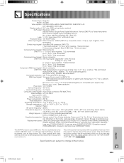
..., Operation manual, Screws for terminal cover Replacement parts Lamp unit (Lamp/cage module) (BQC-XVZ90+++1), Remote control (RRMCGA064WJSA), AA size batteries, Power cord (QACCDA007WJPZ), Terminal cover (GCOVAA116WJKA), Lens cap (CCAPHA004WJ01), Lens cap strap (UBNDT0013CEZZ), Operation manual (TINS-A286WJZZ), Screws for terminal cover (XBBSN40P10000) This SHARP projector uses a DMD chip. This will not affect the picture quality or the life expectancy of dots: 480,000 dots (800 [H] 2 600 [V]) Lens 1-1.2 2 zoom lens, F3.0, f=32.5-44.0 mm Projection lamp 150 W SHP lamp Video input signal...
..., Operation manual, Screws for terminal cover Replacement parts Lamp unit (Lamp/cage module) (BQC-XVZ90+++1), Remote control (RRMCGA064WJSA), AA size batteries, Power cord (QACCDA007WJPZ), Terminal cover (GCOVAA116WJKA), Lens cap (CCAPHA004WJ01), Lens cap strap (UBNDT0013CEZZ), Operation manual (TINS-A286WJZZ), Screws for terminal cover (XBBSN40P10000) This SHARP projector uses a DMD chip. This will not affect the picture quality or the life expectancy of dots: 480,000 dots (800 [H] 2 600 [V]) Lens 1-1.2 2 zoom lens, F3.0, f=32.5-44.0 mm Projection lamp 150 W SHP lamp Video input signal...
Operation Manual
Page 59
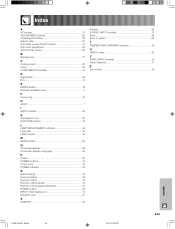
... 41 Auto sync adjustment 35 AUTO SYNC button 35 B Background 37 C Ceiling-mount 22 Clock 33 COMPONENT terminals 13 D Digital shift 38 DVI 14 E ENTER button 19 Exhaust ventilative hole 4 F Focus ring 16 H HDCP 7 I INPUT buttons 24 K Kensington Lock 50 KEYSTONE button 19 L LAMP REPLACEMENT indicator 44 Lens shift 18 LIGHT button 15 M MENU button 26 O On-screen display 36 On-screen display Language 42 P Phase 33 POWER buttons 16 Power cord 12 POWER indicator 44 R Rear+Ceiling 42 Rear projection 23 Remote control 10 Remote control sensor 15 Remote control signal...
... 41 Auto sync adjustment 35 AUTO SYNC button 35 B Background 37 C Ceiling-mount 22 Clock 33 COMPONENT terminals 13 D Digital shift 38 DVI 14 E ENTER button 19 Exhaust ventilative hole 4 F Focus ring 16 H HDCP 7 I INPUT buttons 24 K Kensington Lock 50 KEYSTONE button 19 L LAMP REPLACEMENT indicator 44 Lens shift 18 LIGHT button 15 M MENU button 26 O On-screen display 36 On-screen display Language 42 P Phase 33 POWER buttons 16 Power cord 12 POWER indicator 44 R Rear+Ceiling 42 Rear projection 23 Remote control 10 Remote control sensor 15 Remote control signal...
Operation Manual
Page 60
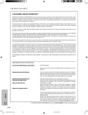
... law. Model Specific Section (In-Home Service) Your Product Model Number & Description: XV-Z90U Projector (Be sure to have Proof of Purchase available. The limited warranty described herein is authorized to make any incidental or consequential economic or property damage. Labor & materials required to remove and reinstall a projector in complex systems including, but not limited to, projectors installed in custom enclosures, projectors connected to...
... law. Model Specific Section (In-Home Service) Your Product Model Number & Description: XV-Z90U Projector (Be sure to have Proof of Purchase available. The limited warranty described herein is authorized to make any incidental or consequential economic or property damage. Labor & materials required to remove and reinstall a projector in complex systems including, but not limited to, projectors installed in custom enclosures, projectors connected to...


