
Operater's Manual
Page 3
... Adjustment 28 o Speed Balancing Adjustment 28 r Neutral Adjustment 28 p Parking Brake Adjustment 29 Return to Neutral Adjustment 30 e Deck Rod Timing Adjustment 31 Deck Leveling Adjustment 31 R Mower Belt Replacement 32 Hydraulic Pump Drive Belt Replacement 34 Battery Maintenance 35 Battery Service 36 Storage 38 Starting After Long Term Storage 38 Troubleshooting 39 Troubleshooting...
... Adjustment 28 o Speed Balancing Adjustment 28 r Neutral Adjustment 28 p Parking Brake Adjustment 29 Return to Neutral Adjustment 30 e Deck Rod Timing Adjustment 31 Deck Leveling Adjustment 31 R Mower Belt Replacement 32 Hydraulic Pump Drive Belt Replacement 34 Battery Maintenance 35 Battery Service 36 Storage 38 Starting After Long Term Storage 38 Troubleshooting 39 Troubleshooting...
Operater's Manual
Page 7
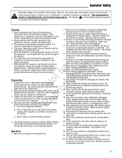
... unit. 5. Evaluate the terrain to determine what accessories and attachments are familiar with the blades running unit unattended. Never raise deck with the instructions, to properly and safely N d perform the job. Always disengage the PTO, set parking brake, stop or... deflector in reverse unless absolutely necessary. Turn off engine before refueling. This mowing deck is responsible for any reason including emptying the grass catchers or unclogging the chute. 16. Use seat belts if provided. 4. Use caution when operating near drop-offs. 6. Read, understand...
... unit. 5. Evaluate the terrain to determine what accessories and attachments are familiar with the blades running unit unattended. Never raise deck with the instructions, to properly and safely N d perform the job. Always disengage the PTO, set parking brake, stop or... deflector in reverse unless absolutely necessary. Turn off engine before refueling. This mowing deck is responsible for any reason including emptying the grass catchers or unclogging the chute. 16. Use seat belts if provided. 4. Use caution when operating near drop-offs. 6. Read, understand...
Operater's Manual
Page 26
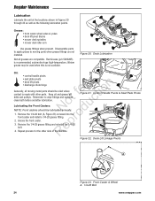
...Front casters should be oiled where contact is made with other side of the machine. Repeat process for tion Generally, all greases are not installed. Deck Lift Linkage Pivots A Figure 23. Red Grease (p/n 5022285) is not available. N d 1. Grease the front caster. Remove the 1/4-28 grease... 1/4-28 bolt. Figure 21. Not all moving parts when grease fittings are compatible. Keep oil and grease off belts and pulleys. Front Caster & Wheel A. 1/4-28 Bolt 24 www.snapper.com Remove the 1/4-28 bolt (A, Figure 23) screwed into the o front caster and install a 1/4-28 grease...
...Front casters should be oiled where contact is made with other side of the machine. Repeat process for tion Generally, all greases are not installed. Deck Lift Linkage Pivots A Figure 23. Red Grease (p/n 5022285) is not available. N d 1. Grease the front caster. Remove the 1/4-28 grease... 1/4-28 bolt. Figure 21. Not all moving parts when grease fittings are compatible. Keep oil and grease off belts and pulleys. Front Caster & Wheel A. 1/4-28 Bolt 24 www.snapper.com Remove the 1/4-28 bolt (A, Figure 23) screwed into the o front caster and install a 1/4-28 grease...

Operater's Manual
Page 34
... in t c the square hole located in the p spring as a concrete floor. Idler Arm B. Slide the drive belt over the edge of the idler arm o (A, Figures 41). A D 32 www.snapper.com Always wear gloves when handling blades or working near blades. 7. A A 8. Measuring the Blade Height 4-1/4" (10...the outside mower blades so they face front-to its lowest cutting position and remove the mower deck guards. 3. Measure the rear tip of the machine. Stationary Idler Pulley C. Deck Drive Belt D. Injury may e result if the breaker bar is prematurely released while R the spring is...
... in t c the square hole located in the p spring as a concrete floor. Idler Arm B. Slide the drive belt over the edge of the idler arm o (A, Figures 41). A D 32 www.snapper.com Always wear gloves when handling blades or working near blades. 7. A A 8. Measuring the Blade Height 4-1/4" (10...the outside mower blades so they face front-to its lowest cutting position and remove the mower deck guards. 3. Measure the rear tip of the machine. Stationary Idler Pulley C. Deck Drive Belt D. Injury may e result if the breaker bar is prematurely released while R the spring is...

Operater's Manual
Page 35
...the ignition key. 2. Lower the mower deck to its lowest cutting position. 3. If the measurement does not equal 7" (17,8 cm), adjust the anchor eyebolt (B). Mower Belt Tensioner Spring B. Retighten the jam nut. Check the Mower Belt Idler Tensioner Spring Length 1. Measure the ...smooth level surface such as a concrete floor. Loosen the jam nut (C). 2. Anchor Eyebolt r n C. AdjustmentNut 33 Adjusting the Mower Belt Idler Spring Length 1. Adjusting the Mower Belt Idler Spring Length A. Regular Maintenance 7" (17,8 cm) A B C D Figure 42. Turn the adjustment nut (D) until a measurement ...
...the ignition key. 2. Lower the mower deck to its lowest cutting position. 3. If the measurement does not equal 7" (17,8 cm), adjust the anchor eyebolt (B). Mower Belt Tensioner Spring B. Retighten the jam nut. Check the Mower Belt Idler Tensioner Spring Length 1. Measure the ...smooth level surface such as a concrete floor. Loosen the jam nut (C). 2. Anchor Eyebolt r n C. AdjustmentNut 33 Adjusting the Mower Belt Idler Spring Length 1. Adjusting the Mower Belt Idler Spring Length A. Regular Maintenance 7" (17,8 cm) A B C D Figure 42. Turn the adjustment nut (D) until a measurement ...
Operater's Manual
Page 36
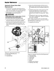
... in the grooves of the belt tension spring can result in the PTO clutch lines up with the PTO clutch mounting tab (A, Figure 43) underneath the engine deck. 8. Reinstall the spring anchor eyebolt (G) into the anchor tab and loosely fasten the nut. Tighten nut. 7. lbs (88 Nm). Crankshaft Bolt ...hooks. Reinstall the PTO clutch to 65 ft. A B H r n E Not rfooductio C ep 5-7/8" R (14.92 cm) B D A F G C C Figure 43. PTO Clutch Mounting Tab B. Hydraulic Pump Drive Belt Replacement A. Pump Drive Belt B. Spring Anchor Eyebolt H. Stationary Idler Pulley 34 www.snapper.com
... in the grooves of the belt tension spring can result in the PTO clutch lines up with the PTO clutch mounting tab (A, Figure 43) underneath the engine deck. 8. Reinstall the spring anchor eyebolt (G) into the anchor tab and loosely fasten the nut. Tighten nut. 7. lbs (88 Nm). Crankshaft Bolt ...hooks. Reinstall the PTO clutch to 65 ft. A B H r n E Not rfooductio C ep 5-7/8" R (14.92 cm) B D A F G C C Figure 43. PTO Clutch Mounting Tab B. Hydraulic Pump Drive Belt Replacement A. Pump Drive Belt B. Spring Anchor Eyebolt H. Stationary Idler Pulley 34 www.snapper.com

Parts Manual
Page 3
...Group - Brand & Model 12 Decals - S/N: 2016499706 & Below o c Seat Mount & Floor Group - Pulleys, Belts & Idler Arm 10 Decals - Safety & Operational 14 Deck Lift Group (S/N: 2015070192 & Above 16 Electrical Group S/N: 2016499706 & Below 18 Electrical Group S/N: 2016499707 & Above 20 ... Table Of Contents Model Components Page 48" (122 cm) Mower Deck Group - S/N: 2016499707 & Above F u Wheel & Tire Group t d Wiring Schematic - 400Z Series S/N: 2016499706 & Below o o Wiring Schematic - 400Z Series S/N: 2016499707 & Above NR e p r Torque Specification Chart ...
...Group - Brand & Model 12 Decals - S/N: 2016499706 & Below o c Seat Mount & Floor Group - Pulleys, Belts & Idler Arm 10 Decals - Safety & Operational 14 Deck Lift Group (S/N: 2015070192 & Above 16 Electrical Group S/N: 2016499706 & Below 18 Electrical Group S/N: 2016499707 & Above 20 ... Table Of Contents Model Components Page 48" (122 cm) Mower Deck Group - S/N: 2016499707 & Above F u Wheel & Tire Group t d Wiring Schematic - 400Z Series S/N: 2016499706 & Below o o Wiring Schematic - 400Z Series S/N: 2016499707 & Above NR e p r Torque Specification Chart ...

Parts Manual
Page 10
All Rights reserved 10 29-Jul-2018 No: 5900528 NRo te pFroord u c t i o n Copyright © Briggs and Stratton. 48" Mower Deck Group - Pulleys, Belts & Idler Arm Note: Unless noted otherwise, use the standard torque specifications Mfg.
All Rights reserved 10 29-Jul-2018 No: 5900528 NRo te pFroord u c t i o n Copyright © Briggs and Stratton. 48" Mower Deck Group - Pulleys, Belts & Idler Arm Note: Unless noted otherwise, use the standard torque specifications Mfg.

Parts Manual
Page 11
...6.25ODX.5ID -(S/N: 2017795056 & Above) 5105145 1 SHIELD, BEARING, 1/2 ID X 2-7/8 OD, CZ -(S/N: 2017795056 & Above) Footnotes: Note: * Replace this part with 5104716YP - 48" Mower Deck Group - Bearing Shield Copyright © Briggs and Stratton. BLK - 5401621A (SV) -(Includes Ref. # 8 & #18) 5021541 2 BUSHING, FLANGE 5044673 1 SPACER, .52 X 1.00 ... CZ WASHER, .53 X 1.50 X .25 NUT, 1/2-13 HEX NYLOCK FLANGE BOLT, 1/2-13 X 2-1/2" GD5 CZ SHIELD, PULLEY BEARING, CZ -(Qty: 3 - Pulleys, Belts & Idler Arm REF NO 1 2 3 4 5 6 7 8 9 10 11 12 13 14 15 16 17 18 19 20 21 22 23 24 25 26 27 28...
...6.25ODX.5ID -(S/N: 2017795056 & Above) 5105145 1 SHIELD, BEARING, 1/2 ID X 2-7/8 OD, CZ -(S/N: 2017795056 & Above) Footnotes: Note: * Replace this part with 5104716YP - 48" Mower Deck Group - Bearing Shield Copyright © Briggs and Stratton. BLK - 5401621A (SV) -(Includes Ref. # 8 & #18) 5021541 2 BUSHING, FLANGE 5044673 1 SPACER, .52 X 1.00 ... CZ WASHER, .53 X 1.50 X .25 NUT, 1/2-13 HEX NYLOCK FLANGE BOLT, 1/2-13 X 2-1/2" GD5 CZ SHIELD, PULLEY BEARING, CZ -(Qty: 3 - Pulleys, Belts & Idler Arm REF NO 1 2 3 4 5 6 7 8 9 10 11 12 13 14 15 16 17 18 19 20 21 22 23 24 25 26 27 28...

Parts Manual
Page 15
... 12 PART NO QTY DESCRIPTION 5103595 1 DECAL, MAIN SAFETY 7101665 1 DECAL, DANGER DO NOT OPERATE W/O DEFLECT 5103184 1 DECAL, WARNING, HAND IN BELT, ENG ONLY 5100280 1 DECAL, Throttle Control -(NOT A SERVICEABLE PART) 5046503 1 DECAL, FUSE LOCATION, 20-20-20-20 -(S/N: 2016499706 & BELOW)... -(LOCATED ON BRACKET BEHIND RH SIDE OF SEAT) 5103196YP 1 DECAL, BELT & BLADE, S50X iCD -(LOCATED UNDER SEAT PLATE) 5101315 1 DECAL, CUT HEIGHT, S50X 5101991 2 DECAL, TRANSAXLE RELEASE -(LOCATED ON LH & RH DECK GUARDS) ----- 1 LABEL, EMISSION CONTROL CALIF. 2008 NRo te pFroord ...
... 12 PART NO QTY DESCRIPTION 5103595 1 DECAL, MAIN SAFETY 7101665 1 DECAL, DANGER DO NOT OPERATE W/O DEFLECT 5103184 1 DECAL, WARNING, HAND IN BELT, ENG ONLY 5100280 1 DECAL, Throttle Control -(NOT A SERVICEABLE PART) 5046503 1 DECAL, FUSE LOCATION, 20-20-20-20 -(S/N: 2016499706 & BELOW)... -(LOCATED ON BRACKET BEHIND RH SIDE OF SEAT) 5103196YP 1 DECAL, BELT & BLADE, S50X iCD -(LOCATED UNDER SEAT PLATE) 5101315 1 DECAL, CUT HEIGHT, S50X 5101991 2 DECAL, TRANSAXLE RELEASE -(LOCATED ON LH & RH DECK GUARDS) ----- 1 LABEL, EMISSION CONTROL CALIF. 2008 NRo te pFroord ...


