
Operater's Manual
Page 3
... Oil Level 25 Transmission Oil Filter Change 25 N d Servicing the Mower Blades 26 Ground Speed Control Lever Adjustment 28 o Speed Balancing Adjustment 28 r Neutral Adjustment 28 p Parking Brake Adjustment 29 Return to Neutral Adjustment 30 e Deck Rod Timing Adjustment 31 Deck Leveling Adjustment 31 R Mower Belt Replacement 32 Hydraulic Pump Drive Belt Replacement 34 Battery Maintenance 35 Battery Service 36 Storage 38 Starting After Long Term Storage 38 Troubleshooting 39 Troubleshooting the Rider 39 Troubleshooting the Mower 40 Troubleshooting Common Cutting Problems...
... Oil Level 25 Transmission Oil Filter Change 25 N d Servicing the Mower Blades 26 Ground Speed Control Lever Adjustment 28 o Speed Balancing Adjustment 28 r Neutral Adjustment 28 p Parking Brake Adjustment 29 Return to Neutral Adjustment 30 e Deck Rod Timing Adjustment 31 Deck Leveling Adjustment 31 R Mower Belt Replacement 32 Hydraulic Pump Drive Belt Replacement 34 Battery Maintenance 35 Battery Service 36 Storage 38 Starting After Long Term Storage 38 Troubleshooting 39 Troubleshooting the Rider 39 Troubleshooting the Mower 40 Troubleshooting Common Cutting Problems...
Operater's Manual
Page 7
... place. 8. r n related injuries. Walk, don't run an engine in an enclosed area. Use caution when operating near drop-offs. 6. Never raise deck with the blades running unit unattended. Turn off engine before resuming operations. Do not change the engine governor setting or overspeed the engine. 15. Slow down and use caution when making turns and when changing directions on level ground, lower implements, disengage drives, engage parking brake, shut off the PTO switch to themselves and...
... place. 8. r n related injuries. Walk, don't run an engine in an enclosed area. Use caution when operating near drop-offs. 6. Never raise deck with the blades running unit unattended. Turn off engine before resuming operations. Do not change the engine governor setting or overspeed the engine. 15. Slow down and use caution when making turns and when changing directions on level ground, lower implements, disengage drives, engage parking brake, shut off the PTO switch to themselves and...
Operater's Manual
Page 8
... given rides in the past may fall off the slope. Remove obstacles such as defined in . These can hide obstacles. 4. Avoid starting, stopping, or turning on a slope), disengage the blade(s) (PTO) and drive slow off and be run over or backed over accidents, which can result in severe injury or death. This spark ignition system complies with grass catchers or other attachments. Do not mow...
... given rides in the past may fall off the slope. Remove obstacles such as defined in . These can hide obstacles. 4. Avoid starting, stopping, or turning on a slope), disengage the blade(s) (PTO) and drive slow off and be run over or backed over accidents, which can result in severe injury or death. This spark ignition system complies with grass catchers or other attachments. Do not mow...
Operater's Manual
Page 9
... expose moving parts. Remove gas-powered equipment from spark and flames. Replace all fuel tank caps and fuel container caps securely. Wrap the blade(s) or wear gloves, and use caution when servicing them . 17. If possible, do not make major repairs on a trailer with factory specifications on the ground. WARNING: Stored energy device. Springs should be removed by your vehicle before making repairs. 22. Units with the engine running . Models equipped with...
... expose moving parts. Remove gas-powered equipment from spark and flames. Replace all fuel tank caps and fuel container caps securely. Wrap the blade(s) or wear gloves, and use caution when servicing them . 17. If possible, do not make major repairs on a trailer with factory specifications on the ground. WARNING: Stored energy device. Springs should be removed by your vehicle before making repairs. 22. Units with the engine running . Models equipped with...

Operater's Manual
Page 13
... PTO has been engaged. START Cranks the engine for proper steering instructions. neutral position the faster the drive wheel will turn. See the Operation section for starting. the REVERSE speed. The hour meter has a self contained power source so that total hours are always visible. 11 The seat can be adjusted forward and back. Starting, stopping, driving, and o u mowing require the combined use for tion Figure 2. Seat Adjustment Lever NOTE: Never leave the ignition switch in specific...
... PTO has been engaged. START Cranks the engine for proper steering instructions. neutral position the faster the drive wheel will turn. See the Operation section for starting. the REVERSE speed. The hour meter has a self contained power source so that total hours are always visible. 11 The seat can be adjusted forward and back. Starting, stopping, driving, and o u mowing require the combined use for tion Figure 2. Seat Adjustment Lever NOTE: Never leave the ignition switch in specific...

Operater's Manual
Page 14
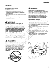
...& Controls Parking Brake DISENGAGE Releases the parking brake. ENGAGE Locks the parking brake. Pull the parking brake lever up and the oil expands. The transmission oil reservoirs are located beneath the operator's seat and in front of the mower deck. Fuel Tank Cap To remove the cap, turn counterclockwise. t c Throttle Control o u The throttle controls engine speed. PTO (Power Take Off) Switch The PTO switch engages and disengages the mower. Transmission oil is equipped with two transmission oil reservoirs. Push the lever down to R open the choke. NOTE: To start...
...& Controls Parking Brake DISENGAGE Releases the parking brake. ENGAGE Locks the parking brake. Pull the parking brake lever up and the oil expands. The transmission oil reservoirs are located beneath the operator's seat and in front of the mower deck. Fuel Tank Cap To remove the cap, turn counterclockwise. t c Throttle Control o u The throttle controls engine speed. PTO (Power Take Off) Switch The PTO switch engages and disengages the mower. Transmission oil is equipped with two transmission oil reservoirs. Push the lever down to R open the choke. NOTE: To start...
Operater's Manual
Page 15
... operate on the unit. Never fill the tank when the t c engine is highly flammable and must be handled with care. See Seat Adjustment • Adjust the height of the mower deck to ride on slopes greater than the width of the rear wheels of slopes, not up any for instructions and oil recommendations. • Fill the fuel tanks with a rear-mounted grass catcher. reason, engage the parking brake, disengage the PTO, stop or park tractor over injuring the operator...
... operate on the unit. Never fill the tank when the t c engine is highly flammable and must be handled with care. See Seat Adjustment • Adjust the height of the mower deck to ride on slopes greater than the width of the rear wheels of slopes, not up any for instructions and oil recommendations. • Fill the fuel tanks with a rear-mounted grass catcher. reason, engage the parking brake, disengage the PTO, stop or park tractor over injuring the operator...

Operater's Manual
Page 18
... the ignition switch and turn it for at FULL THROTTLE when mowing. N d In the event of an emergency the engine can now be o stopped by pulling the handle up and pushing Then fully close the choke by hand. For normal engine shut down fully) 3. first becoming familiar with the location and function of the fuel tanks. Remove the key. Disengaged Position (Free-wheel Position) 16 www.snapper.com Operation Starting the Engine Pushing the...
... the ignition switch and turn it for at FULL THROTTLE when mowing. N d In the event of an emergency the engine can now be o stopped by pulling the handle up and pushing Then fully close the choke by hand. For normal engine shut down fully) 3. first becoming familiar with the location and function of the fuel tanks. Remove the key. Disengaged Position (Free-wheel Position) 16 www.snapper.com Operation Starting the Engine Pushing the...
Operater's Manual
Page 21
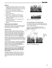
... it is is disengaged, the ground speed control levers are locked in one third of rainfall, the o u prevailing temperature, and the lawn's overall condition. Make sure the PTO switch is between three and five inches high. Proper Cutting Height 8. Typically, you should mow the grass when it is also effected by pushing the PTO switch down completely.. Begin mowing. Incremental Cutting Cutting off the PTO by the type of mowing system you...
... it is is disengaged, the ground speed control levers are locked in one third of rainfall, the o u prevailing temperature, and the lawn's overall condition. Make sure the PTO switch is between three and five inches high. Proper Cutting Height 8. Typically, you should mow the grass when it is also effected by pushing the PTO switch down completely.. Begin mowing. Incremental Cutting Cutting off the PTO by the type of mowing system you...
Operater's Manual
Page 22
... Broadcasting Always operate the engine at full throttle when mowing. Engine Speed & Ground Speed for manual gear models). Mow at full throttle r when mowing. Your mower has a deep dish deck to allow freer circulation of the blades and prevents many common cutting problems. Use an appropriate ground speed for the thickness and height of grass one direction, then recut the lawn by mowing perpendicular N d to the previous cut the grass shorter than longer blades. Operation When and...
... Broadcasting Always operate the engine at full throttle when mowing. Engine Speed & Ground Speed for manual gear models). Mow at full throttle r when mowing. Your mower has a deep dish deck to allow freer circulation of the blades and prevents many common cutting problems. Use an appropriate ground speed for the thickness and height of grass one direction, then recut the lawn by mowing perpendicular N d to the previous cut the grass shorter than longer blades. Operation When and...

Operater's Manual
Page 25
...carburetor, near the fuel pump. fo tio Change Oil & Filter 1. Oil Drain Hose B. Fuel Tank Selection Valve A 6. Remove the engine oil dipstick (F) that is located in the area. If replacement parts are required, make sure to catch any spilled p oil. Using the appropriate tools, remove the cap (B) o from the fuel filter. Engine Oil Drain (Briggs & Stratton shown) A. Remove the fuel cap. 2. Install and hand tighten the fuel cap. Do not remove fuel filter when engine is hot, as the original parts or fire could result. 4. Disconnect the negative battery cable. 2. Locate...
...carburetor, near the fuel pump. fo tio Change Oil & Filter 1. Oil Drain Hose B. Fuel Tank Selection Valve A 6. Remove the engine oil dipstick (F) that is located in the area. If replacement parts are required, make sure to catch any spilled p oil. Using the appropriate tools, remove the cap (B) o from the fuel filter. Engine Oil Drain (Briggs & Stratton shown) A. Remove the fuel cap. 2. Install and hand tighten the fuel cap. Do not remove fuel filter when engine is hot, as the original parts or fire could result. 4. Disconnect the negative battery cable. 2. Locate...
Operater's Manual
Page 33
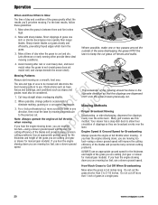
Remove the cutting height adjustment pin from proper inflation levels. Park the machine on top of the deck lift pedal arm. Check the tires from in front o u of the rear 2 x 4 blocks. Adjust Lift Rod Timing Figure 38. 2 x 4 Locations position. Place a 1/4" (0,64 cm) thick spacer on a flat, level surface. Park the machine on the lift pivot arm and secure with the 1/2" clevis pin previously removed. Disengage the PTO, engage the parking brake, turn off the engine, and...
Remove the cutting height adjustment pin from proper inflation levels. Park the machine on top of the deck lift pedal arm. Check the tires from in front o u of the rear 2 x 4 blocks. Adjust Lift Rod Timing Figure 38. 2 x 4 Locations position. Place a 1/4" (0,64 cm) thick spacer on a flat, level surface. Park the machine on the lift pivot arm and secure with the 1/2" clevis pin previously removed. Disengage the PTO, engage the parking brake, turn off the engine, and...

Operater's Manual
Page 34
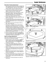
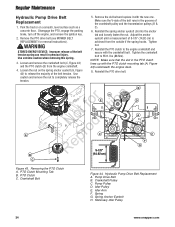
... idler arm o (A, Figures 41). Install the drive belt on the breaker bar. 7. Run the mower under tension. 4. Regular Maintenance CAUTION A Avoid injury! A A 8. Measure the rear tip of the blade from the cutting edge to break-in the p spring as a concrete floor. Repeat this process for about 5 minutes to the ground. Disengage the PTO, engage the parking r n brake, turn off the engine, and remove the ignition key. Idler Arm B. Spindle Pulley WARNING ro Use extreme caution when rotating the idler arm...
... idler arm o (A, Figures 41). Install the drive belt on the breaker bar. 7. Run the mower under tension. 4. Regular Maintenance CAUTION A Avoid injury! A A 8. Measure the rear tip of the blade from the cutting edge to break-in the p spring as a concrete floor. Repeat this process for about 5 minutes to the ground. Disengage the PTO, engage the parking r n brake, turn off the engine, and remove the ignition key. Idler Arm B. Spindle Pulley WARNING ro Use extreme caution when rotating the idler arm...
Operater's Manual
Page 36
... the engine deck. 8. Make sure the V-side of the belt runs in the grooves of the belt tension spring can result in the PTO clutch lines up with the new one. Adjust the anchor eyebolt until a measurement of the belt tension. Pump Drive Belt B. Idler Pulley E. Tighten nut. 7. Hydraulic Pump Drive Belt Replacement A. Spring Anchor Eyebolt H. Disengage the PTO, engage the parking brake, turn off the engine, and remove the ignition key. 2. Use extreme caution when removing this spring. 3. Use caution and remove the nut...
... the engine deck. 8. Make sure the V-side of the belt runs in the grooves of the belt tension spring can result in the PTO clutch lines up with the new one. Adjust the anchor eyebolt until a measurement of the belt tension. Pump Drive Belt B. Idler Pulley E. Tighten nut. 7. Hydraulic Pump Drive Belt Replacement A. Spring Anchor Eyebolt H. Disengage the PTO, engage the parking brake, turn off the engine, and remove the ignition key. 2. Use extreme caution when removing this spring. 3. Use caution and remove the nut...

Operater's Manual
Page 38
... level will not accept a normal charge until the specific gravity of same cable to same post marked positive (+) on engine block of discharged battery (wired to measure the specific gravity of a battery charger and hydrometer, have the battery serviced by your dealer. Jump Starting With Auxiliary (Booster) Battery A dead battery or one too weak to cover the plate (fill vehicle away from the battery; Connect positive (+) cable to start N d engine. batteries...
... level will not accept a normal charge until the specific gravity of same cable to same post marked positive (+) on engine block of discharged battery (wired to measure the specific gravity of a battery charger and hydrometer, have the battery serviced by your dealer. Jump Starting With Auxiliary (Booster) Battery A dead battery or one too weak to cover the plate (fill vehicle away from the battery; Connect positive (+) cable to start N d engine. batteries...

Operater's Manual
Page 40
... exhaust outlet and air cleaner. 4. Check fluid levels. 9. Be sure to distant sources of ignition and ignite, causing risk of oil to do when storing your unit temporarily or in between uses: Handle gasoline carefully. Prepare the mower deck for a long period of unauthorized use a fuel stabilizer and have chosen to use , remove the spark plug (s) and put in a cool, dry place and fully charged engine only outdoors...
... exhaust outlet and air cleaner. 4. Check fluid levels. 9. Be sure to distant sources of ignition and ignite, causing risk of oil to do when storing your unit temporarily or in between uses: Handle gasoline carefully. Prepare the mower deck for a long period of unauthorized use a fuel stabilizer and have chosen to use , remove the spark plug (s) and put in a cool, dry place and fully charged engine only outdoors...

Operater's Manual
Page 41
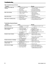
... Fuse blown. Gas is black. Fuel mixture too rich. 2. Move choke control to cool, then refill the fuel tank. 5. Tighten loose connections. 10. See engine manual. 13. Clean air filter. incorrectly gapped. (See engine manual.) 1. See engine manual. 2. Engine starts hard or runs poorly. PTO (electric clutch) switch in closed position. 6. Wiring loose or broken. Safety interlock switch r faulty. 12. Move ground speed control levers to continue operating properly. Visually check wiring & replace broken or frayed wires. Check choke adjustment. 2. See engine manual...
... Fuse blown. Gas is black. Fuel mixture too rich. 2. Move choke control to cool, then refill the fuel tank. 5. Tighten loose connections. 10. See engine manual. 13. Clean air filter. incorrectly gapped. (See engine manual.) 1. See engine manual. 2. Engine starts hard or runs poorly. PTO (electric clutch) switch in closed position. 6. Wiring loose or broken. Safety interlock switch r faulty. 12. Move ground speed control levers to continue operating properly. Visually check wiring & replace broken or frayed wires. Check choke adjustment. 2. See engine manual...
Operater's Manual
Page 42
...or rough pulleys. p Using incorrect belt. Idler pulley spring broken or not eproperly attached. RMower drive belt broken. 1. See authorized service dealer for repair. 1. Decrease Ground Speed. 3. Cut tall grass at maximum cutting height during first pass. 4. Cut grass with discharge pointing toward previously cut grass. Check and replace as required. 2. Remove, sharpen, and balance blades. Repair or replace. 2. Repair or replace as needed. 2. Replace drive belt. 1. Electrical wiring damage. 1. Locate & repair damaged wire. 2. PTO clutch not adjusted 2. See PTO Clutch...
...or rough pulleys. p Using incorrect belt. Idler pulley spring broken or not eproperly attached. RMower drive belt broken. 1. See authorized service dealer for repair. 1. Decrease Ground Speed. 3. Cut tall grass at maximum cutting height during first pass. 4. Cut grass with discharge pointing toward previously cut grass. Check and replace as required. 2. Remove, sharpen, and balance blades. Repair or replace. 2. Repair or replace as needed. 2. Replace drive belt. 1. Electrical wiring damage. 1. Locate & repair damaged wire. 2. PTO clutch not adjusted 2. See PTO Clutch...
Operater's Manual
Page 47
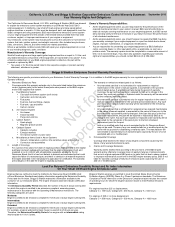
... engine running time for which the engine has been shown to a B&S distribution center, servicing dealer, or other emissions-related assemblies. Consequential Coverage Coverage shall extend to conform with the Operating & Maintenance Instructions. that it is identical in the owner's manual supplied, is certified to be emissions compliant for 500 hours of emissions parts Resources Board; For example, a typical walk-behind lawn mower is used : Moderate: Engine...
... engine running time for which the engine has been shown to a B&S distribution center, servicing dealer, or other emissions-related assemblies. Consequential Coverage Coverage shall extend to conform with the Operating & Maintenance Instructions. that it is identical in the owner's manual supplied, is certified to be emissions compliant for 500 hours of emissions parts Resources Board; For example, a typical walk-behind lawn mower is used : Moderate: Engine...

Parts Manual
Page 3
...-2018 Pulleys, Belts & Idler Arm 10 Decals - S/N: 2016499707 & Above F u Wheel & Tire Group t d Wiring Schematic - 400Z Series S/N: 2016499706 & Below o o Wiring Schematic - 400Z Series S/N: 2016499707 & Above NR e p r Torque Specification Chart 34 36 40 42 44 46 48 50 52 54 56 Copyright © Briggs and Stratton. S/N: 2016499706 & Below o c Seat Mount & Floor Group - Table Of Contents Model Components Page 48" (122 cm) Mower Deck Group - Housing, Covers, Spindles & Blades 8 48" Mower Deck Group - Single Tank 28 Hydraulic Group 30 Instrument & Control Panel...
...-2018 Pulleys, Belts & Idler Arm 10 Decals - S/N: 2016499707 & Above F u Wheel & Tire Group t d Wiring Schematic - 400Z Series S/N: 2016499706 & Below o o Wiring Schematic - 400Z Series S/N: 2016499707 & Above NR e p r Torque Specification Chart 34 36 40 42 44 46 48 50 52 54 56 Copyright © Briggs and Stratton. S/N: 2016499706 & Below o c Seat Mount & Floor Group - Table Of Contents Model Components Page 48" (122 cm) Mower Deck Group - Housing, Covers, Spindles & Blades 8 48" Mower Deck Group - Single Tank 28 Hydraulic Group 30 Instrument & Control Panel...


