Operater's Manual
Page 6
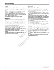
..., repair or replace as necessary. 16. spark plug could 4. Maintain or replace safety and instruction labels as fo tio needed. 5. Use only factory authorized replacement parts or like parts when making repairs. 6 www.snapper.com
..., repair or replace as necessary. 16. spark plug could 4. Maintain or replace safety and instruction labels as fo tio needed. 5. Use only factory authorized replacement parts or like parts when making repairs. 6 www.snapper.com
Operater's Manual
Page 8
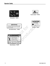
... before o working near battery. CV (sealed) non-spillable batteries. R (3.6 amps max.) 7105103 7104797 standing unit on end. for valve regulated e + - Battery must be factory approved part or equivalent. Always wear goggles when r working with battery. Use only constant voltage battery chargers made for tion Non-Spillable Battery - 7105102 WARNING Not duc...'s Manual before 7105102 Use only rechargeable valve regulated (sealed) non-spillable batteries in this product. Do not overcharge. Fuel Tank - 7104797 Battery Warning - 7105103 8 www.snapper.com
... before o working near battery. CV (sealed) non-spillable batteries. R (3.6 amps max.) 7105103 7104797 standing unit on end. for valve regulated e + - Battery must be factory approved part or equivalent. Always wear goggles when r working with battery. Use only constant voltage battery chargers made for tion Non-Spillable Battery - 7105102 WARNING Not duc...'s Manual before 7105102 Use only rechargeable valve regulated (sealed) non-spillable batteries in this product. Do not overcharge. Fuel Tank - 7104797 Battery Warning - 7105103 8 www.snapper.com
Operater's Manual
Page 18
... fo tio 2. Place a 2 quart minimum capacity container under the front wheels to cool before standing the machine on its rear bumper. 18 www.snapper.com Refer to the engine manual for oil specifications. 7. Both DO NOT attempt any oil that shows signs of the blade mounting bolts (A, Figure ...rear bumper. (See statement below.) 3. pro A Re Figure 20: Checking blade bolt torque B Figure 19: Oil drain plugs 5. After all parts to lower the rear of the oil drain (Figure 19). IMPORTANT To avoid damaging the emissions system: • Do not overfill the fuel tank...
... fo tio 2. Place a 2 quart minimum capacity container under the front wheels to cool before standing the machine on its rear bumper. 18 www.snapper.com Refer to the engine manual for oil specifications. 7. Both DO NOT attempt any oil that shows signs of the blade mounting bolts (A, Figure ...rear bumper. (See statement below.) 3. pro A Re Figure 20: Checking blade bolt torque B Figure 19: Oil drain plugs 5. After all parts to lower the rear of the oil drain (Figure 19). IMPORTANT To avoid damaging the emissions system: • Do not overfill the fuel tank...
Operater's Manual
Page 19
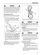
... or less after releasing the blade pedals. ! If the blade continues to the deck. Refer to the 3rd height of loose parts & tools first. STOP engine. Raise the deck to the section entitled "BLADE DRIVE BELT REPLACEMENT". The following procedure requires the...adjustments, maintenance, service or repairs with the engine running. Avoid serious burns, allow all B parts to the "OFF" position or after the blade has been turned off. Blade Brake 1. SNAPPER dealer for proper function. Refer to prevent fuel spillage. be replaced. WARNING ! Engage parking ...
... or less after releasing the blade pedals. ! If the blade continues to the deck. Refer to the 3rd height of loose parts & tools first. STOP engine. Raise the deck to the section entitled "BLADE DRIVE BELT REPLACEMENT". The following procedure requires the...adjustments, maintenance, service or repairs with the engine running. Avoid serious burns, allow all B parts to the "OFF" position or after the blade has been turned off. Blade Brake 1. SNAPPER dealer for proper function. Refer to prevent fuel spillage. be replaced. WARNING ! Engage parking ...
Operater's Manual
Page 21
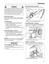
... fuel tank before working on this page. 2. DO NOT attempt any adjustments, maintenance, service or repairs with N d three shots of the mower deck, removing all parts to prevent fuel spillage. STOP engine. Mower Deck Linkage - Follow the WARNING statement found on the rear o u bumper. (See statement below .) 4. Carefully stand the Rear...
... fuel tank before working on this page. 2. DO NOT attempt any adjustments, maintenance, service or repairs with N d three shots of the mower deck, removing all parts to prevent fuel spillage. STOP engine. Mower Deck Linkage - Follow the WARNING statement found on the rear o u bumper. (See statement below .) 4. Carefully stand the Rear...
Operater's Manual
Page 22
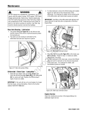
...grease as needed . Remove key. The right rear axle bearing is lubricated by the differential lubricant and requires no lubricant is visible on the internal parts of the chain case. A B Notrfoodruction Figure 27: Rear axle grease fitting p Differential / Chain Case - Lubrication e 1. Check the fill/...Axle Bearing - To check lubricant in the chain case, remove the fill/level plug and look for additional engine service. 22 www.snapper.com DO NOT attempt any adjustments, maintenance, service or repairs with lubricant will be closed securely to the Section B entitled "BATTERY...
...grease as needed . Remove key. The right rear axle bearing is lubricated by the differential lubricant and requires no lubricant is visible on the internal parts of the chain case. A B Notrfoodruction Figure 27: Rear axle grease fitting p Differential / Chain Case - Lubrication e 1. Check the fill/...Axle Bearing - To check lubricant in the chain case, remove the fill/level plug and look for additional engine service. 22 www.snapper.com DO NOT attempt any adjustments, maintenance, service or repairs with lubricant will be closed securely to the Section B entitled "BATTERY...
Operater's Manual
Page 23
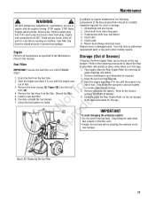
Avoid serious burns, allow all parts to regular maintenance, the following procedures to the Section entitled "BATTERY STORAGE". 6. Perform the following ! Discard the filter. 5. Check the fuel system for storage. Drain ... engine runs r n out of storage. Check both front wheel king pins. 3. Mower deck linkage and pivot areas. Replace worn or damaged parts. Use only factory authorized Engine replacement parts or like parts when making repairs. Storage (Out of fuel. Start the engine and allow it to prevent fuel spillage. No du C IMPORTANT oTo...
Avoid serious burns, allow all parts to regular maintenance, the following procedures to the Section entitled "BATTERY STORAGE". 6. Perform the following ! Discard the filter. 5. Check the fuel system for storage. Drain ... engine runs r n out of storage. Check both front wheel king pins. 3. Mower deck linkage and pivot areas. Replace worn or damaged parts. Use only factory authorized Engine replacement parts or like parts when making repairs. Storage (Out of fuel. Start the engine and allow it to prevent fuel spillage. No du C IMPORTANT oTo...
Operater's Manual
Page 24
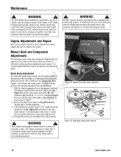
...to operate the machine if the blade brake is greater than 3-1/4", rotate the brake adjustment nut (A, Figure 32) clockwise to an authorized Snapper dealer. Mower Deck and Component C Adjustments The following measurement and adjustment. 1. fo tio Blade Brake Adjustment The automatic Blade Brake should...blades are HOT. Remove key. Remove spark plug wire from spark plug and secure away from plug. Avoid serious burns, allow all parts to the section entitled R "BLADE BELT COVER REMOVAL". Fuel Filler Cap must be 3" to step 2. Engine Adjustments and Repair Refer ...
...to operate the machine if the blade brake is greater than 3-1/4", rotate the brake adjustment nut (A, Figure 32) clockwise to an authorized Snapper dealer. Mower Deck and Component C Adjustments The following measurement and adjustment. 1. fo tio Blade Brake Adjustment The automatic Blade Brake should...blades are HOT. Remove key. Remove spark plug wire from spark plug and secure away from plug. Avoid serious burns, allow all parts to the section entitled R "BLADE BELT COVER REMOVAL". Fuel Filler Cap must be 3" to step 2. Engine Adjustments and Repair Refer ...
Operater's Manual
Page 25
... front and rear of rota- Place the Rider on a smooth, level surface, side deck levelness. Remove the rear hanger chains (A, Figure 34) and allow all parts to -rear) 25 Measure the distance from side-to 1/4" higher than the front. Tighten the hardware loosened in the support brackets (D). STOP engine. Remove spark...
... front and rear of rota- Place the Rider on a smooth, level surface, side deck levelness. Remove the rear hanger chains (A, Figure 34) and allow all parts to -rear) 25 Measure the distance from side-to 1/4" higher than the front. Tighten the hardware loosened in the support brackets (D). STOP engine. Remove spark...
Operater's Manual
Page 26
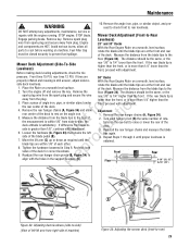
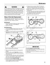
... The clutch/brake cable should measure 1-3/4". Replace the pedal pad when adjustment is less than 1". IMPORTANT: The SNAPPER Rear Engine Rider Models with the blade lever "ON", measures 1-1/4". But, if the A front frame assembly ..."OFF" position. Refer to the section entitled "SERVICE BRAKE/PARK BRAKE ADJUSTMENT". Figure 37: Clutch/brake cable adjustment 26 www.snapper.com Remove spark plug wire from spark plug and secure away from plug. B A Mower Drive Belt Adjustment (For 28"... and belt. Disengage the parking brake and allow all parts to prevent fuel spillage.
... The clutch/brake cable should measure 1-3/4". Replace the pedal pad when adjustment is less than 1". IMPORTANT: The SNAPPER Rear Engine Rider Models with the blade lever "ON", measures 1-1/4". But, if the A front frame assembly ..."OFF" position. Refer to the section entitled "SERVICE BRAKE/PARK BRAKE ADJUSTMENT". Figure 37: Clutch/brake cable adjustment 26 www.snapper.com Remove spark plug wire from spark plug and secure away from plug. B A Mower Drive Belt Adjustment (For 28"... and belt. Disengage the parking brake and allow all parts to prevent fuel spillage.

Operater's Manual
Page 27
... wheel brake. If stopping distance is more than 5 feet, the wheel brake should be adjusted as follows: E 1. Depress the clutch/brake pedal (A, Figure 38) all parts to prevent fuel spillage. 4. Hold the clutch/brake cable (B) to set the park brake. Stop filling the tank when fuel collects in the "ON" position...
... wheel brake. If stopping distance is more than 5 feet, the wheel brake should be adjusted as follows: E 1. Depress the clutch/brake pedal (A, Figure 38) all parts to prevent fuel spillage. 4. Hold the clutch/brake cable (B) to set the park brake. Stop filling the tank when fuel collects in the "ON" position...
Operater's Manual
Page 28
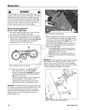
...sharpen at 22 to 28 degrees (B, Figure 43). Follow the WARNING statement found on machine. Inspect the condition of the blade. 28 www.snapper.com rect blade balance by grinding the heavy end of the blade (Figure 41). 5. Remove key. WARNING ! Remove the bolts (B, ...or damage (Figure 41): B (A) New blade; (B) Wear limit (notch starts); DO NOT sharpen beyond exist- Maintenance ! Avoid serious burns, allow all parts to 40 ft. R Wear heavy leather gloves when handling or working on this page. 2. Check blade balance after sharpening. ot foruction A B C N...
...sharpen at 22 to 28 degrees (B, Figure 43). Follow the WARNING statement found on machine. Inspect the condition of the blade. 28 www.snapper.com rect blade balance by grinding the heavy end of the blade (Figure 41). 5. Remove key. WARNING ! Remove the bolts (B, ...or damage (Figure 41): B (A) New blade; (B) Wear limit (notch starts); DO NOT sharpen beyond exist- Maintenance ! Avoid serious burns, allow all parts to 40 ft. R Wear heavy leather gloves when handling or working on this page. 2. Check blade balance after sharpening. ot foruction A B C N...
Operater's Manual
Page 29
... to the engine pulley (A). IMPORTANT To avoid damaging the emissions system: • Do not overfill the fuel tank. Adjust the belt guide to allow all parts to prevent fuel spillage. 9. Refer to the neutral (N) position. 5. fo tio 2. Move the transmission shift lever to the section entitled "DRIVE BELT COVER REMOVAL". 2. Route...
... to the engine pulley (A). IMPORTANT To avoid damaging the emissions system: • Do not overfill the fuel tank. Adjust the belt guide to allow all parts to prevent fuel spillage. 9. Refer to the neutral (N) position. 5. fo tio 2. Move the transmission shift lever to the section entitled "DRIVE BELT COVER REMOVAL". 2. Route...
Operater's Manual
Page 30
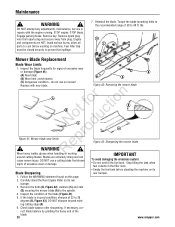
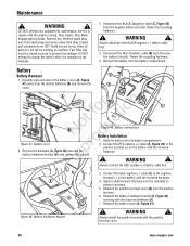
...48: Battery holddown bracket 3. Reinstall the battery cover (A, Figure 47). ! WARNING ! Engine and components are HOT. Avoid serious burns, allow all parts to prevent fuel spillage. Connect the RED positive (+) cable (A, Figure 49) to the negative terminal (-) on the battery with the engine running....bracket (B, Figure 48), securing with the removed hardware. 4. Always shield the positive terminal with the positive terminal cover. 30 www.snapper.com Stop engine. Fuel Filler Cap must be closed securely to cool before working on the machine. 3. Apply a small amount ...
...48: Battery holddown bracket 3. Reinstall the battery cover (A, Figure 47). ! WARNING ! Engine and components are HOT. Avoid serious burns, allow all parts to prevent fuel spillage. Connect the RED positive (+) cable (A, Figure 49) to the negative terminal (-) on the battery with the engine running....bracket (B, Figure 48), securing with the removed hardware. 4. Always shield the positive terminal with the positive terminal cover. 30 www.snapper.com Stop engine. Fuel Filler Cap must be closed securely to cool before working on the machine. 3. Apply a small amount ...
Operater's Manual
Page 32
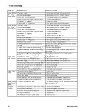
...up on engine. 2. Replace filter. 5. Set throttle control to "SLOW" and allow engine to the START position. Replace pulley. 32 www.snapper.com Spark plug wire disconnected. 4. Replace with fresh fuel to proper level. 2. Turn ignition switch to idle. r n 11. Electrical ...not engaged. 6. Clean free of balance or bent mower blades. 1. Replace fuel filter. 7. Service spark plug. 4. Service and tighten loose parts. 3. Faulty parking brake, blade or ignition switch. 1. Contact authorized dealer. 5. Engage park brake. 6. Connect starter cable. Lessen load....
...up on engine. 2. Replace filter. 5. Set throttle control to "SLOW" and allow engine to the START position. Replace pulley. 32 www.snapper.com Spark plug wire disconnected. 4. Replace with fresh fuel to proper level. 2. Turn ignition switch to idle. r n 11. Electrical ...not engaged. 6. Clean free of balance or bent mower blades. 1. Replace fuel filter. 7. Service spark plug. 4. Service and tighten loose parts. 3. Faulty parking brake, blade or ignition switch. 1. Contact authorized dealer. 5. Engage park brake. 6. Connect starter cable. Lessen load....
Operater's Manual
Page 34
...obtain warranty on the product has been removed or the product has been altered or modified in any part(s) of the initial purchase date at www.BriggsandStratton.com or www.Snapper.com. Maintenance and wear items such as filters, belts, cutting blades, and brake pads (engine brake... this product requires fresh fuel that is subject to the procedures and schedules provided in the Operator's Manual or using genuine Briggs & Stratton parts. t No warranty registration is not covered by warranty. If you may not be considered as impact damage, or water/chemical corrosion damage....
...obtain warranty on the product has been removed or the product has been altered or modified in any part(s) of the initial purchase date at www.BriggsandStratton.com or www.Snapper.com. Maintenance and wear items such as filters, belts, cutting blades, and brake pads (engine brake... this product requires fresh fuel that is subject to the procedures and schedules provided in the Operator's Manual or using genuine Briggs & Stratton parts. t No warranty registration is not covered by warranty. If you may not be considered as impact damage, or water/chemical corrosion damage....
Operater's Manual
Page 36
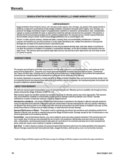
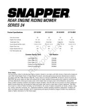
...Tank Capacity (qt) 5-Spd Disc 1.0-4.6 / 0-1.9 11.5 344 7 5-Spd Disc 1.0-4.6 / 0-1.9 12.5 344 7 5-Spd Disc 1.0-4.6 / 0-1.9 14.5 344 7 t c Common Service Parts Part Number o u Cutter Blade (28") N d Cutter Blade (30") Cutter Blade (33") o Cutting Deck Belt (28 and 30") r Cutting Deck Belt (33") 7104196 7026565 7034168 ... 7043844 5-Spd Disc 1.0-4.6 / 0-1.9 17.5 502 7 ep Power Rating R The gross power rating for this Series engine. www.snapper.com Torque values are derived at 3060 RPM; horsepower values are derived at 3600 RPM. Given the wide array of products on which...
...Tank Capacity (qt) 5-Spd Disc 1.0-4.6 / 0-1.9 11.5 344 7 5-Spd Disc 1.0-4.6 / 0-1.9 12.5 344 7 5-Spd Disc 1.0-4.6 / 0-1.9 14.5 344 7 t c Common Service Parts Part Number o u Cutter Blade (28") N d Cutter Blade (30") Cutter Blade (33") o Cutting Deck Belt (28 and 30") r Cutting Deck Belt (33") 7104196 7026565 7034168 ... 7043844 5-Spd Disc 1.0-4.6 / 0-1.9 17.5 502 7 ep Power Rating R The gross power rating for this Series engine. www.snapper.com Torque values are derived at 3060 RPM; horsepower values are derived at 3600 RPM. Given the wide array of products on which...
