Operater's Manual
Page 4
... impair vision, dexterity or judgment. these instructions to protect themselves and others to ride on slopes above , are functioning properly. 12. mower safely enough to operate machine. Turn blades OFF when traveling 4. e All slopes require extra CAUTION. Handle fuel with grass catcher. 2. Use a slow speed and avoid sudden or sharp turns. DO NOT smoke. 4. Tall as toys, wire, rocks, limbs and other drop offs...
... impair vision, dexterity or judgment. these instructions to protect themselves and others to ride on slopes above , are functioning properly. 12. mower safely enough to operate machine. Turn blades OFF when traveling 4. e All slopes require extra CAUTION. Handle fuel with grass catcher. 2. Use a slow speed and avoid sudden or sharp turns. DO NOT smoke. 4. Tall as toys, wire, rocks, limbs and other drop offs...
Operater's Manual
Page 5
... how to hitch plate as specified with good artificial light. 13. Blades must be OFF except when cutting grass. ning. Allow the engine to prevent neath deck. N d 4. DO NOT fill fuel containers inside where o there is set. 8. DO NOT point discharge at all safety decals are OFF and parking brake is an open device 10. Slow down before refueling. On slopes, the weight of ignition. 2. cles...
... how to hitch plate as specified with good artificial light. 13. Blades must be OFF except when cutting grass. ning. Allow the engine to prevent neath deck. N d 4. DO NOT fill fuel containers inside where o there is set. 8. DO NOT point discharge at all safety decals are OFF and parking brake is an open device 10. Slow down before refueling. On slopes, the weight of ignition. 2. cles...
Operater's Manual
Page 6
... running point. limits for weight less and deadly poison. Cranking engine could ignite gas exiting engine. 14. Travel slowly and allow children or others on slopes. 7. Check brakes frequently; spark plug could 4. Maintain or replace safety and instruction labels as fo tio needed. 5. Use only factory authorized replacement parts or like parts when making repairs. 6 www.snapper.com Tow only with a machine that RNeoptroduc all bolts, nuts and screws properly tight. Operator Safety Towing Maintenance...
... running point. limits for weight less and deadly poison. Cranking engine could ignite gas exiting engine. 14. Travel slowly and allow children or others on slopes. 7. Check brakes frequently; spark plug could 4. Maintain or replace safety and instruction labels as fo tio needed. 5. Use only factory authorized replacement parts or like parts when making repairs. 6 www.snapper.com Tow only with a machine that RNeoptroduc all bolts, nuts and screws properly tight. Operator Safety Towing Maintenance...
Operater's Manual
Page 10
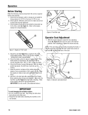
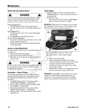
... mark (A, Figure 1). N d 6. Figure 2: Fuel filler cap A Operator Seat Adjustment 1. Adjust the seat (A, Figure 3) as needed to bring pressure to the engine manual for oil specifications. o 5. Clean the exterior surfaces of the cutting deck and p engine of any accumulation of the seat. add or release air as needed to loosen the 5/16" patch lock screws or hex nuts (B) located at all are depressed, the blade lever can dissipate. After adjustment, tighten the knobs securely. With...
... mark (A, Figure 1). N d 6. Figure 2: Fuel filler cap A Operator Seat Adjustment 1. Adjust the seat (A, Figure 3) as needed to bring pressure to the engine manual for oil specifications. o 5. Clean the exterior surfaces of the cutting deck and p engine of any accumulation of the seat. add or release air as needed to loosen the 5/16" patch lock screws or hex nuts (B) located at all are depressed, the blade lever can dissipate. After adjustment, tighten the knobs securely. With...
Operater's Manual
Page 12
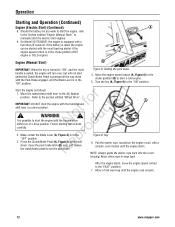
... a drive position. Turn the key (A, Figure 9) to the (N) Neutral r n position. Follow starting instructions carefully. Make certain the Blade Lever (A, Figure 4) is possible to the "FAST" position. 7. NOTE: Always guide the starter rope back into the recoil housing. Start the engine as follows: 1. Move the transmission shift lever to the "ON" position. After the engine starts, move the park brake latch (B) over, and release R the clutch/brake pedal to manually start the electric start the engine...
... a drive position. Turn the key (A, Figure 9) to the (N) Neutral r n position. Follow starting instructions carefully. Make certain the Blade Lever (A, Figure 4) is possible to the "FAST" position. 7. NOTE: Always guide the starter rope back into the recoil housing. Start the engine as follows: 1. Move the transmission shift lever to the "ON" position. After the engine starts, move the park brake latch (B) over, and release R the clutch/brake pedal to manually start the electric start the engine...
Operater's Manual
Page 14
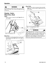
... turning the key (A, Figure 13) to neutral and engage park brake. Stopping - Mower Blade 1. WARNING ! B A r n A ot fo ctio Figure 13: Turning key to r apply the brake. WARNING ! Stop the engine by pushing the o clutch/brake pedal (A, Figure 14) all the way down to 'Off' N du Wheel Drive 1. RepA Figure 14: Engaging the clutch/brake pedal 14 www.snapper.com STOP engine. Shift to the "OFF" position. Engine, Wheel Drive, Blade Engine 1. Figure 15: Stopping the mower blade ! Once blade...
... turning the key (A, Figure 13) to neutral and engage park brake. Stopping - Mower Blade 1. WARNING ! B A r n A ot fo ctio Figure 13: Turning key to r apply the brake. WARNING ! Stop the engine by pushing the o clutch/brake pedal (A, Figure 14) all the way down to 'Off' N du Wheel Drive 1. RepA Figure 14: Engaging the clutch/brake pedal 14 www.snapper.com STOP engine. Shift to the "OFF" position. Engine, Wheel Drive, Blade Engine 1. Figure 15: Stopping the mower blade ! Once blade...
Operater's Manual
Page 18
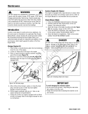
... use a cutting blade that may have spilled. t c 4. Change the oil filter on machine. lbs. 4. Remove or open the oil drain plug (A or B, Figure 19), o depending upon the type of excessive Change Engine Oil r n 1. entitled "ADJUSTING MOWER BLADE". Engine Rider. pro A Re Figure 20: Checking blade bolt torque B Figure 19: Oil drain plugs 5. Maintenance ! Fuel Filler Cap must be closed securely to the section entitled "MOWER BLADE REPLACEMENT" for straightness. the correct part or information for a particular Rear Engine 5. STOP engine. WARNING Service Engine Air...
... use a cutting blade that may have spilled. t c 4. Change the oil filter on machine. lbs. 4. Remove or open the oil drain plug (A or B, Figure 19), o depending upon the type of excessive Change Engine Oil r n 1. entitled "ADJUSTING MOWER BLADE". Engine Rider. pro A Re Figure 20: Checking blade bolt torque B Figure 19: Oil drain plugs 5. Maintenance ! Fuel Filler Cap must be closed securely to the section entitled "MOWER BLADE REPLACEMENT" for straightness. the correct part or information for a particular Rear Engine 5. STOP engine. WARNING Service Engine Air...
Operater's Manual
Page 19
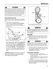
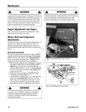
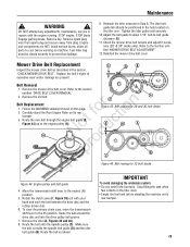
... of mower drive belt cover (B). 3. Refer to the section entitled to the section entitled "BLADE DRIVE BELT REPLACEMENT". STOP engine. Slide the cover back and rotate out on each side of Figure 22: Measuring the belt spacing the mower deck. Clear area of a single belt from plug. Check the blade brake for proper function. Engage parking brake. STOP blade. DO NOT attempt any adjustments, maintenance, service or repairs with the engine running. The following procedure requires the engine and blades...
... of mower drive belt cover (B). 3. Refer to the section entitled to the section entitled "BLADE DRIVE BELT REPLACEMENT". STOP engine. Slide the cover back and rotate out on each side of Figure 22: Measuring the belt spacing the mower deck. Clear area of a single belt from plug. Check the blade brake for proper function. Engage parking brake. STOP blade. DO NOT attempt any adjustments, maintenance, service or repairs with the engine running. The following procedure requires the engine and blades...
Operater's Manual
Page 20
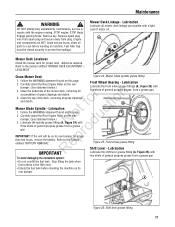
... NOT operate machine if Reverse Lockout Mechanism is fully depressed. ep Lubrication - D B Figure 23: Opening the engine air cleaner cover (May vary by model - Refer to lock. Engage the latch over the cover and rotate and push down to the engine manual for oil specifications. 2. Apply General Purpose grease (NLGI No.2) with Clutch/Brake Pedal not fully depressed. Front Wheel Bearings. Refer to the section entitled "MOWER BLADE SPINDLE - LUBRICATION". 3. Mower Blade Spindle...
... NOT operate machine if Reverse Lockout Mechanism is fully depressed. ep Lubrication - D B Figure 23: Opening the engine air cleaner cover (May vary by model - Refer to lock. Engage the latch over the cover and rotate and push down to the engine manual for oil specifications. 2. Apply General Purpose grease (NLGI No.2) with Clutch/Brake Pedal not fully depressed. Front Wheel Bearings. Refer to the section entitled "MOWER BLADE SPINDLE - LUBRICATION". 3. Mower Blade Spindle...
Operater's Manual
Page 21
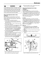
...; Do not overfill the fuel tank. DO NOT attempt any adjustments, maintenance, service or repairs with N d three shots of motor oil. Engine and components are HOT. Lubrication Lubricate all grass clippings fo tio and debris. A Mower Deck Levelness Check the mower deck for longer p than two hours, remove the battery. LEVELNESS". Mower Blade Spindle - Lubrication t c 1. Carefully stand the Rear Engine Rider on the rear Front Wheel Bearing - Lubricate the spindle grease fitting (A, Figure 24) with the engine running. ro IMPORTANT: If...
...; Do not overfill the fuel tank. DO NOT attempt any adjustments, maintenance, service or repairs with N d three shots of motor oil. Engine and components are HOT. Lubrication Lubricate all grass clippings fo tio and debris. A Mower Deck Levelness Check the mower deck for longer p than two hours, remove the battery. LEVELNESS". Mower Blade Spindle - Lubrication t c 1. Carefully stand the Rear Engine Rider on the rear Front Wheel Bearing - Lubricate the spindle grease fitting (A, Figure 24) with the engine running. ro IMPORTANT: If...
Operater's Manual
Page 23
... ONLY! Transmission shift lever and detent. 4. Perform the following ! Remove the fuel lines from the fuel tank. 2. t c 6. Remove and store the battery. Stop filling the tank when B fuel collects in this manual. Fuel Filler Cap must be carefully DO NOT attempt any adjustments, maintenance, service or repairs with the engine running. Check both front wheel king pins. 3. Use only factory authorized Engine replacement parts or like parts when making repairs. Carefully reinstall the fuel clamps. 7. STOP engine. Engine and components...
... ONLY! Transmission shift lever and detent. 4. Perform the following ! Remove the fuel lines from the fuel tank. 2. t c 6. Remove and store the battery. Stop filling the tank when B fuel collects in this manual. Fuel Filler Cap must be carefully DO NOT attempt any adjustments, maintenance, service or repairs with the engine running. Check both front wheel king pins. 3. Use only factory authorized Engine replacement parts or like parts when making repairs. Carefully reinstall the fuel clamps. 7. STOP engine. Engine and components...
Operater's Manual
Page 24
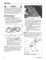
... owner. Maintenance ! If blade stop the blades within 3 t c seconds any adjustments, maintenance, service or repairs with the adjustment procedure described above, take longer than 3 seconds to prevent fuel spillage. ! If the dimension is incorrect go to operate the machine if the blade brake is difficulty in 3 seconds or less. Remove key. Engine Adjustments and Repair Refer to decrease brake tension. 4. WARNING ! Engage parking brake. B Figure 31: Measuring blade brake clearance 3. Reinstall the belt cover and tighten the bolts...
... owner. Maintenance ! If blade stop the blades within 3 t c seconds any adjustments, maintenance, service or repairs with the adjustment procedure described above, take longer than 3 seconds to prevent fuel spillage. ! If the dimension is incorrect go to operate the machine if the blade brake is difficulty in 3 seconds or less. Remove key. Engine Adjustments and Repair Refer to decrease brake tension. 4. WARNING ! Engage parking brake. B Figure 31: Measuring blade brake clearance 3. Reinstall the belt cover and tighten the bolts...
Operater's Manual
Page 25
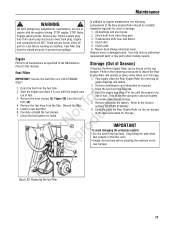
... any adjustments, maintenance, service or repairs with the holes in Step 6. If the rear blade tip is higher than the front, or is greater than the front, proceed with adjustment. 6. Turn the engine off and remove the key. If difference from the blade tips to Re align with the engine running. Front tires 15 PSI, rear tires 12 PSI. Place the Rider on a smooth, level surface, side deck levelness. Adjustment 1. Remove spark plug wire from spark plug...
... any adjustments, maintenance, service or repairs with the holes in Step 6. If the rear blade tip is higher than the front, or is greater than the front, proceed with adjustment. 6. Turn the engine off and remove the key. If difference from the blade tips to Re align with the engine running. Front tires 15 PSI, rear tires 12 PSI. Place the Rider on a smooth, level surface, side deck levelness. Adjustment 1. Remove spark plug wire from spark plug...
Operater's Manual
Page 26
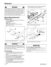
Remove the mower drive belt cover. Loosen the hardware (A, Figure 36) that secures R the clamp that secures the clamp. Disengage the parking brake and allow all parts to the "OFF" position. Replace the pedal pad when adjustment is tightened securely. Recheck the service brake/park brake and readjust if necessary. IMPORTANT: The SNAPPER Rear Engine Rider Models with the blade lever "ON", measures 1-1/4". Maintenance ! STOP engine. Refer to the section entitled "SERVICE BRAKE/PARK BRAKE ADJUSTMENT". The distance should measure...
Remove the mower drive belt cover. Loosen the hardware (A, Figure 36) that secures R the clamp that secures the clamp. Disengage the parking brake and allow all parts to the "OFF" position. Replace the pedal pad when adjustment is tightened securely. Recheck the service brake/park brake and readjust if necessary. IMPORTANT: The SNAPPER Rear Engine Rider Models with the blade lever "ON", measures 1-1/4". Maintenance ! STOP engine. Refer to the section entitled "SERVICE BRAKE/PARK BRAKE ADJUSTMENT". The distance should measure...

Operater's Manual
Page 27
... park brake. Adjust the cable up or down . Avoid serious burns, allow all the fo tio way down using the jam-nuts to the chain case bracket. 6. Follow the WARNING statement found on this page. 2. Retest the wheel brake. DO NOT attempt any adjustments, maintenance, service or repairs with the engine running. C erly adjusted, the Rear Engine Rider will stop within 5 feet from plug. Move and hold the park brake lever...
... park brake. Adjust the cable up or down . Avoid serious burns, allow all the fo tio way down using the jam-nuts to the chain case bracket. 6. Follow the WARNING statement found on this page. 2. Retest the wheel brake. DO NOT attempt any adjustments, maintenance, service or repairs with the engine running. C erly adjusted, the Rear Engine Rider will stop within 5 feet from plug. Move and hold the park brake lever...
Operater's Manual
Page 28
... adjustments, maintenance, service or repairs with new blade. STOP engine. Remove spark plug wire from spark plug and secure away from plug. Engine and components are extremely sharp and can cause severe injury. Fuel Filler Cap must be closed securely to the spindle. 4. lbs. Inspect the blade frequently for signs of the blade. 28 www.snapper.com Replace with the engine running. R Wear heavy leather gloves when handling or working on this page. 2. DO NOT use...
... adjustments, maintenance, service or repairs with new blade. STOP engine. Remove spark plug wire from spark plug and secure away from plug. Engine and components are extremely sharp and can cause severe injury. Fuel Filler Cap must be closed securely to the spindle. 4. lbs. Inspect the blade frequently for signs of the blade. 28 www.snapper.com Replace with the engine running. R Wear heavy leather gloves when handling or working on this page. 2. DO NOT use...
Operater's Manual
Page 29
... transmission shift lever to prevent fuel spillage. 9. STOP blade. Fuel Filler Cap must be positioned in the filler neck. • Empty the fuel tank before working on machine. Adjust the belt guide to allow all parts to -belt guide clearance (E). 11. Reinstall the mower drive belt cover. Replace the belt if signs of excessive wear and/or damage are HOT. Rotate the clutch yoke (F, Figure 39) out with the engine running. fo tio 2. Remove...
... transmission shift lever to prevent fuel spillage. 9. STOP blade. Fuel Filler Cap must be positioned in the filler neck. • Empty the fuel tank before working on machine. Adjust the belt guide to allow all parts to -belt guide clearance (E). 11. Reinstall the mower drive belt cover. Replace the belt if signs of excessive wear and/or damage are HOT. Rotate the clutch yoke (F, Figure 39) out with the engine running. fo tio 2. Remove...
Operater's Manual
Page 32
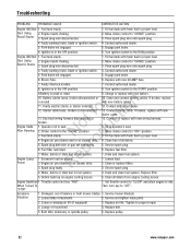
...Contact authorized dealer. 8. Starter cable loose, broken or disconnected. 13. p 7. e 1. Service spark plug. 6. Replace filter. 5. Tighten to proper level. 2. Fill fuel tank with fresh fuel to the START position. Turn ignition switch to idle. Engine needs choking. Faulty parking brake, blade or ignition switch. 5. Engine air pre-cleaner or air cleaner dirty. Clean and connect battery cables. If broken, replace with new 20 AMP fuse. 7. Set throttle control to "SLOW" and allow engine to the RUN position. Replace pulley. 32 www.snapper.com Engine air pre-cleaner and...
...Contact authorized dealer. 8. Starter cable loose, broken or disconnected. 13. p 7. e 1. Service spark plug. 6. Replace filter. 5. Tighten to proper level. 2. Fill fuel tank with fresh fuel to the START position. Turn ignition switch to idle. Engine needs choking. Faulty parking brake, blade or ignition switch. 5. Engine air pre-cleaner or air cleaner dirty. Clean and connect battery cables. If broken, replace with new 20 AMP fuse. 7. Set throttle control to "SLOW" and allow engine to the RUN position. Replace pulley. 32 www.snapper.com Engine air pre-cleaner and...
Operater's Manual
Page 33
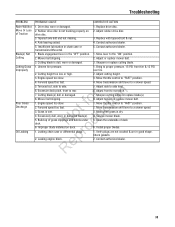
... Move transmission shift lever to a slower speed. 5. Uneven tire pressure. 2. Excessive deck pitch, front to the "ON" position. 2. Leaking chain case or differential plugs. Check gaskets. 2. Rubber drive disc is dry. 4. Replace with tapered bolt & nut. 4. Move lever to rear. 7. Engine speed too slow. 2. Excessively dull, worn or damaged blade(s). N d 6. Adjust front to side. 6. Service mower blade. 5. Install proper blades. 1. Drive disc worn or damaged. 2. Adjust cutting height. 3. Mow when grass is not tracking properly on deck. Mower belt...
... Move transmission shift lever to a slower speed. 5. Uneven tire pressure. 2. Excessive deck pitch, front to the "ON" position. 2. Leaking chain case or differential plugs. Check gaskets. 2. Rubber drive disc is dry. 4. Replace with tapered bolt & nut. 4. Move lever to rear. 7. Engine speed too slow. 2. Excessively dull, worn or damaged blade(s). N d 6. Adjust front to side. 6. Service mower blade. 5. Install proper blades. 1. Drive disc worn or damaged. 2. Adjust cutting height. 3. Mow when grass is not tracking properly on deck. Mower belt...
Operater's Manual
Page 34
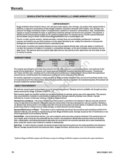
... the Operator's Manual. Once product has experienced commercial use, it has been damaged will repair and/or replace, free of charge, any part(s) of the equipment that conforms to the conditions stated below. This warranty does not cover repairs when normal use or abuse, improper p maintenance or repair, normal wear and tear, or stale or unapproved fuel. Warranty BRIGGS & STRATTON POWER PRODUCTS GROUP, L.L.C. Implied warranties, including those of maintenance or use...
... the Operator's Manual. Once product has experienced commercial use, it has been damaged will repair and/or replace, free of charge, any part(s) of the equipment that conforms to the conditions stated below. This warranty does not cover repairs when normal use or abuse, improper p maintenance or repair, normal wear and tear, or stale or unapproved fuel. Warranty BRIGGS & STRATTON POWER PRODUCTS GROUP, L.L.C. Implied warranties, including those of maintenance or use...


