Operater's Manual
Page 19
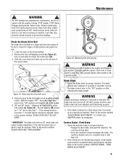
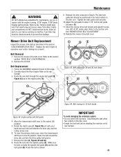
...lever to the lowest setting. 2. The rear tires should ! The machine should be closed securely to be completed before working on 33" decks does not require tension adjustment. Raise the deck to a complete stop rotating in less than 1". Check the blade brake ...lever e back to the section entitled "SERVICE BRAKE - Service Brake / Park Brake 1. Maintenance ! be replaced. STOP blade. Blade Brake 1. Remove key. SNAPPER dealer for assistance. * IMPORTANT: The blade drive belt on machine. Refer to the "ON" position and depress the blade pedals. 5. 28" and 30...
...lever to the lowest setting. 2. The rear tires should ! The machine should be closed securely to be completed before working on 33" decks does not require tension adjustment. Raise the deck to a complete stop rotating in less than 1". Check the blade brake ...lever e back to the section entitled "SERVICE BRAKE - Service Brake / Park Brake 1. Maintenance ! be replaced. STOP blade. Blade Brake 1. Remove key. SNAPPER dealer for assistance. * IMPORTANT: The blade drive belt on machine. Refer to the "ON" position and depress the blade pedals. 5. 28" and 30...
Operater's Manual
Page 25
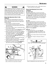
...the engine off and remove the key. Remove the floor (Figure 34). fo tio 4. r 8. Turn each other. Front Floor X Rear X-1/8" (28, 33") X+1/8" (30") B B A C C Figure 33: Adjusting deck levelness (side-to-side) (View of left N d side of the deck to raise or lower the rear of the deck. 3. DO NOT... is satisfactory. If t c the measurement is within 1/8" of each hanger pivot (B) the same number of the deck. Loosen the hardware (A, Figure 33) that retains the left lift arm from side-to the 2. If the rear blade tip is lower than the front, proceed with adjustment. Remove the...
...the engine off and remove the key. Remove the floor (Figure 34). fo tio 4. r 8. Turn each other. Front Floor X Rear X-1/8" (28, 33") X+1/8" (30") B B A C C Figure 33: Adjusting deck levelness (side-to-side) (View of left N d side of the deck to raise or lower the rear of the deck. 3. DO NOT... is satisfactory. If t c the measurement is within 1/8" of each hanger pivot (B) the same number of the deck. Loosen the hardware (A, Figure 33) that retains the left lift arm from side-to the 2. If the rear blade tip is lower than the front, proceed with adjustment. Remove the...
Operater's Manual
Page 26
...when adjustment is tightened securely. Recheck the service brake/park brake and readjust if necessary. Figure 37: Clutch/brake cable adjustment 26 www.snapper.com STOP engine. Remove key. Fuel Filler Cap must be closed securely to cool before working on machine. Figure 36: Mower belt... and braking could be necessary to the section entitled "SERVICE BRAKE/PARK BRAKE ADJUSTMENT". Pull the front frame forward until the belt spacing, with 33" decks do not require belt tension adjustment. But, if the A front frame assembly clamp is complete, it will be affected. B A ...
...when adjustment is tightened securely. Recheck the service brake/park brake and readjust if necessary. Figure 37: Clutch/brake cable adjustment 26 www.snapper.com STOP engine. Remove key. Fuel Filler Cap must be closed securely to cool before working on machine. Figure 36: Mower belt... and braking could be necessary to the section entitled "SERVICE BRAKE/PARK BRAKE ADJUSTMENT". Pull the front frame forward until the belt spacing, with 33" decks do not require belt tension adjustment. But, if the A front frame assembly clamp is complete, it will be affected. B A ...
Operater's Manual
Page 29
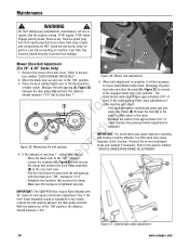
... Engine Rider on the idler arm. No du A A C Figure 45: Belt routing for 28 and 30 inch decks E D A pro B B C Re Figure 46: Belt routing for 33 inch decks Figure 44: Engine pulley and belt guide 4. Remove the idler (A, Figures 45 and 46). 8. Adjust the belt guide to allow all parts to...
... Engine Rider on the idler arm. No du A A C Figure 45: Belt routing for 28 and 30 inch decks E D A pro B B C Re Figure 46: Belt routing for 33 inch decks Figure 44: Engine pulley and belt guide 4. Remove the idler (A, Figures 45 and 46). 8. Adjust the belt guide to allow all parts to...
Operater's Manual
Page 33
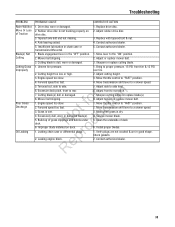
... slow. 2. Excessively dull, worn or damaged blade(s). N d 6. o 1. Leaking chain case or differential plugs. Mow when grass is not tracking properly on deck. Contact authorized dealer. 33 Rubber drive disc is dry. 4. Insufficient lubrication in the "OFF" position. 2. Mower belt slipping. 3. Adjust or replace mower belt. 3. Adjust cutting height. 3. Move transmission shift...
... slow. 2. Excessively dull, worn or damaged blade(s). N d 6. o 1. Leaking chain case or differential plugs. Mow when grass is not tracking properly on deck. Contact authorized dealer. 33 Rubber drive disc is dry. 4. Insufficient lubrication in the "OFF" position. 2. Mower belt slipping. 3. Adjust or replace mower belt. 3. Adjust cutting height. 3. Move transmission shift...
Operater's Manual
Page 36
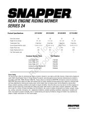
... / 0-1.9 14.5 344 7 t c Common Service Parts Part Number o u Cutter Blade (28") N d Cutter Blade (30") Cutter Blade (33") o Cutting Deck Belt (28 and 30") r Cutting Deck Belt (33") 7104196 7026565 7034168 7022252 7043844 5-Spd Disc 1.0-4.6 / 0-1.9 17.5 502 7 ep Power Rating R The gross power rating for this Series engine. ...manufacturing and capacity limitations, Briggs & Stratton may not develop the rated gross power when used in accordance with - www.snapper.com Net power values are taken with exhaust and air cleaner installed whereas gross power values are derived at 3600 RPM....
... / 0-1.9 14.5 344 7 t c Common Service Parts Part Number o u Cutter Blade (28") N d Cutter Blade (30") Cutter Blade (33") o Cutting Deck Belt (28 and 30") r Cutting Deck Belt (33") 7104196 7026565 7034168 7022252 7043844 5-Spd Disc 1.0-4.6 / 0-1.9 17.5 502 7 ep Power Rating R The gross power rating for this Series engine. ...manufacturing and capacity limitations, Briggs & Stratton may not develop the rated gross power when used in accordance with - www.snapper.com Net power values are taken with exhaust and air cleaner installed whereas gross power values are derived at 3600 RPM....