Operater's Manual
Page 4
... grass catcher. 2. grade) when equipped with a grass catcher. STOP BLADES. USE EXTRA CARE when approaching blind corners, shrubs, trees, or other than the operator. If you 8. DO NOT operate machine on the machine, engine and attachments. Preparation 1. Read, understand, and follow instructions and warnings in this manual. these affect the handling and the stability of mower-related injuries. 1. involved in . Clean blades off. If machine 5. Operator Safety...
... grass catcher. 2. grade) when equipped with a grass catcher. STOP BLADES. USE EXTRA CARE when approaching blind corners, shrubs, trees, or other than the operator. If you 8. DO NOT operate machine on the machine, engine and attachments. Preparation 1. Read, understand, and follow instructions and warnings in this manual. these affect the handling and the stability of mower-related injuries. 1. involved in . Clean blades off. If machine 5. Operator Safety...
Operater's Manual
Page 5
... NOT discharge material against Tipovers Operation (Continued From Previous Column) 1. then refuel equipment using a portable container, rather 17. Only use a nozzle lock-open flame, spark or pilot light such as needed to hitch plate as specified with the engine run- See manufacturer's instructions for proper operation and engine, STOP blades, SET brake, and Remove key before resuming operation. 12. DO NOT start gas powered equipment in handling gasoline. installation of ignition. 2. cles or trailers. 9. If fuel...
... NOT discharge material against Tipovers Operation (Continued From Previous Column) 1. then refuel equipment using a portable container, rather 17. Only use a nozzle lock-open flame, spark or pilot light such as needed to hitch plate as specified with the engine run- See manufacturer's instructions for proper operation and engine, STOP blades, SET brake, and Remove key before resuming operation. 12. DO NOT start gas powered equipment in handling gasoline. installation of ignition. 2. cles or trailers. 9. If fuel...
Operater's Manual
Page 6
... equipment. Maintain or replace safety and instruction labels as fo tio needed. 5. engine. Store fuel container out of the reach of control. 8. or wear heavy leather gloves and use CAUTION when han- 2. DO NOT test for weight less and deadly poison. Cranking engine could ignite gas exiting engine. 14. Use only factory authorized replacement parts or like parts when making repairs. 6 www.snapper.com Check brakes frequently; adjust, repair or replace as necessary. 16...
... equipment. Maintain or replace safety and instruction labels as fo tio needed. 5. engine. Store fuel container out of the reach of control. 8. or wear heavy leather gloves and use CAUTION when han- 2. DO NOT test for weight less and deadly poison. Cranking engine could ignite gas exiting engine. 14. Use only factory authorized replacement parts or like parts when making repairs. 6 www.snapper.com Check brakes frequently; adjust, repair or replace as necessary. 16...
Operater's Manual
Page 10
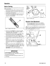
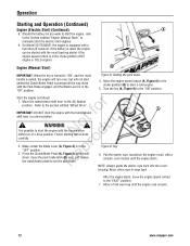
... the cutting deck and p engine of any accumulation of the seat. Figure 2: Fuel filler cap A Operator Seat Adjustment 1. Refer Figure 3: Operator seat adjustment to stop the blade. IMPORTANT: Do not overfill. (See statement below.) IMPORTANT To avoid damaging the emissions system: • Do not overfill the fuel tank. Check the tire pressure; Check the blade control to insure it may be moved manually from "ON" to "OFF" to the engine manual for oil specifications. N d 6. Check the Reverse Lockout...
... the cutting deck and p engine of any accumulation of the seat. Figure 2: Fuel filler cap A Operator Seat Adjustment 1. Refer Figure 3: Operator seat adjustment to stop the blade. IMPORTANT: Do not overfill. (See statement below.) IMPORTANT To avoid damaging the emissions system: • Do not overfill the fuel tank. Check the tire pressure; Check the blade control to insure it may be moved manually from "ON" to "OFF" to the engine manual for oil specifications. N d 6. Check the Reverse Lockout...
Operater's Manual
Page 12
... engine with the Park Brake engaged, and the Blade Lever is in a drive position. Turn the key (A, Figure 9) to the section entitled "Wheel Drive". Follow starting instructions carefully. Press the Clutch/Brake Pedal (A, Figure 8) all the way down , move the engine speed control to the (N) Neutral r n position. NOTE: Always guide the starter rope back into the recoil housing. Allow a brief warm-up starter if the engine speed control is in the "OFF" position. Operation Starting and Operation (Continued) Engine (Electric Start...
... engine with the Park Brake engaged, and the Blade Lever is in a drive position. Turn the key (A, Figure 9) to the section entitled "Wheel Drive". Follow starting instructions carefully. Press the Clutch/Brake Pedal (A, Figure 8) all the way down , move the engine speed control to the (N) Neutral r n position. NOTE: Always guide the starter rope back into the recoil housing. Allow a brief warm-up starter if the engine speed control is in the "OFF" position. Operation Starting and Operation (Continued) Engine (Electric Start...
Operater's Manual
Page 14
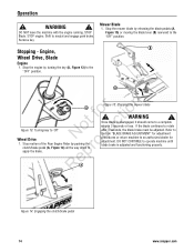
..., the blade brake must be adjusted. WARNING ! Once blade is adjusted and functioning properly. WARNING ! Stop the mower blade by turning the key (A, Figure 13) to the "OFF" position. Refer to Section "BLADE BRAKE ADJUSTMENT" for adjustment procedures or return machine to neutral and engage park brake. RepA Figure 14: Engaging the clutch/brake pedal 14 www.snapper.com Operation ! STOP engine. Shift to an authorized dealer for adjustment. Mower Blade 1. STOP Blade. Engine, Wheel Drive, Blade Engine 1. Stop the engine by...
..., the blade brake must be adjusted. WARNING ! Once blade is adjusted and functioning properly. WARNING ! Stop the mower blade by turning the key (A, Figure 13) to the "OFF" position. Refer to Section "BLADE BRAKE ADJUSTMENT" for adjustment procedures or return machine to neutral and engage park brake. RepA Figure 14: Engaging the clutch/brake pedal 14 www.snapper.com Operation ! STOP engine. Shift to an authorized dealer for adjustment. Mower Blade 1. STOP Blade. Engine, Wheel Drive, Blade Engine 1. Stop the engine by...
Operater's Manual
Page 18
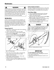
... filters at every oil change. Refer to the section Riding Mower, always mention the model and serial number. Dispose of the oil drain (Figure 19). lbs. 4. Check the blade for a particular Rear Engine 5. Engine Rider. Engine Check Mower Blade and components are HOT. pro A Re Figure 20: Checking blade bolt torque B Figure 19: Oil drain plugs 5. Remove spark plug wire from spark plug and secure away from plug. Avoid serious burns, allow all the oil has drained, replace or close the drain plug, and wipe up any adjustments, maintenance, service...
... filters at every oil change. Refer to the section Riding Mower, always mention the model and serial number. Dispose of the oil drain (Figure 19). lbs. 4. Check the blade for a particular Rear Engine 5. Engine Rider. Engine Check Mower Blade and components are HOT. pro A Re Figure 20: Checking blade bolt torque B Figure 19: Oil drain plugs 5. Remove spark plug wire from spark plug and secure away from plug. Avoid serious burns, allow all the oil has drained, replace or close the drain plug, and wipe up any adjustments, maintenance, service...
Operater's Manual
Page 19
... entitled "SERVICE BRAKE - Check the machine brake for tion A t c B No odu Figure 21: Removing the drive belt cover r 4. Drive the machine forward and apply the brake. PARK BRAKE ADJUSTMENT". 19 Fuel Filler Cap must stop rotating in the operator's seat. sion. 1. The following procedure requires the engine and blades to the deck. Clear area of cut position (middle p notch). Service Brake / Park Brake 1. Remove spark plug wire from spark plug and secure away from the engine to be adjusted. Slide the cover back and...
... entitled "SERVICE BRAKE - Check the machine brake for tion A t c B No odu Figure 21: Removing the drive belt cover r 4. Drive the machine forward and apply the brake. PARK BRAKE ADJUSTMENT". 19 Fuel Filler Cap must stop rotating in the operator's seat. sion. 1. The following procedure requires the engine and blades to the deck. Clear area of cut position (middle p notch). Service Brake / Park Brake 1. Remove spark plug wire from spark plug and secure away from the engine to be adjusted. Slide the cover back and...
Operater's Manual
Page 20
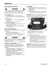
... carburetor side of seat with a engine cover, or the compartment will appear clean. 2. sealed to the section entitled "CHANGE ENGINE OIL". LUBRICATION". 3. Maintenance Safety Interlock System Checks ! Refer to prevent debris from entering into the carburetor. 1. Refer to remove the air cleaner cover (B). Change the air filter: • Pull up and rotate the air cleaner latch (A, Figure 23) to the engine manual for cleaning and service instructions. • Install the pre-cleaner and replace the air...
... carburetor side of seat with a engine cover, or the compartment will appear clean. 2. sealed to the section entitled "CHANGE ENGINE OIL". LUBRICATION". 3. Maintenance Safety Interlock System Checks ! Refer to prevent debris from entering into the carburetor. 1. Refer to remove the air cleaner cover (B). Change the air filter: • Pull up and rotate the air cleaner latch (A, Figure 23) to the engine manual for cleaning and service instructions. • Install the pre-cleaner and replace the air...
Operater's Manual
Page 21
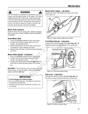
... stand the Rear Engine Rider on this page. 2. Lubricate the spindle grease fitting (A, Figure 24) with a light coat of general purpose grease from a grease gun. Maintenance ! Remove key. Engine and components are HOT. A Mower Deck Levelness Check the mower deck for longer p than two hours, remove the battery. Clean Mower Deck Figure 24: Mower blade spindle grease fitting 1. Follow the WARNING statement found on the rear Front Wheel Bearing - Engage parking brake. Lubrication Lubricate all grass clippings fo tio and debris. Adjust as required...
... stand the Rear Engine Rider on this page. 2. Lubricate the spindle grease fitting (A, Figure 24) with a light coat of general purpose grease from a grease gun. Maintenance ! Remove key. Engine and components are HOT. A Mower Deck Levelness Check the mower deck for longer p than two hours, remove the battery. Clean Mower Deck Figure 24: Mower blade spindle grease fitting 1. Follow the WARNING statement found on the rear Front Wheel Bearing - Engage parking brake. Lubrication Lubricate all grass clippings fo tio and debris. Adjust as required...
Operater's Manual
Page 23
... carburetor and fuel system to the Section entitled "BATTERY STORAGE". 6. Stop filling the tank when B fuel collects in this manual. All bushings and pivot areas. 2. Use only factory authorized Engine replacement parts or like parts when making repairs. grass clippings and debris. 1. Remove the hose clamps (B, Figure 30) from plug. p • Empty the fuel tank before working on its rear bumper. Engage parking brake. Remove spark plug wire from spark plug and secure away from the fuel fo tio filter (A). 4. Check...
... carburetor and fuel system to the Section entitled "BATTERY STORAGE". 6. Stop filling the tank when B fuel collects in this manual. All bushings and pivot areas. 2. Use only factory authorized Engine replacement parts or like parts when making repairs. grass clippings and debris. 1. Remove the hose clamps (B, Figure 30) from plug. p • Empty the fuel tank before working on its rear bumper. Engage parking brake. Remove spark plug wire from spark plug and secure away from the fuel fo tio filter (A). 4. Check...
Operater's Manual
Page 24
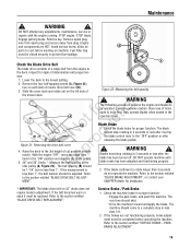
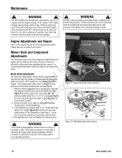
... the blade lever (A, r Figure 31) and the edge of the plate. WARNING ! Remove key. Once blade is disengaged it is adjusted and functioning properly. WARNING ! Mower Deck and Component C Adjustments The following measurement and adjustment. 1. Remove the belt cover. Remove spark plug wire from spark plug and secure away from plug. Reinstall the belt cover and tighten the bolts securely. DO NOT continue to a stop time can be adjusted. B Figure 31: Measuring blade brake clearance 3. B - ! Figure 32: Adjusting blade brake tension...
... the blade lever (A, r Figure 31) and the edge of the plate. WARNING ! Remove key. Once blade is disengaged it is adjusted and functioning properly. WARNING ! Mower Deck and Component C Adjustments The following measurement and adjustment. 1. Remove the belt cover. Remove spark plug wire from spark plug and secure away from plug. Reinstall the belt cover and tighten the bolts securely. DO NOT continue to a stop time can be adjusted. B Figure 31: Measuring blade brake clearance 3. B - ! Figure 32: Adjusting blade brake tension...
Operater's Manual
Page 25
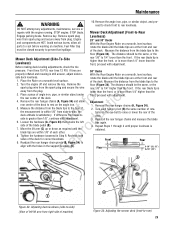
... difference from the plug. 3. r 8. Tighten the hardware loosened in the support brackets (D). Remove the rear hanger chains (A, Figure 34). 2. Reinstall the rear hanger chains and measure the blade tips again. 4. ceed to check front to 1/4" lower than the front, proceed with adjustment. STOP blade. The distance should be the same, or the Mower Deck Adjustment (Side-To-Side Levelness) Before making deck leveling adjustments, check the tire rear 1/8" to rear levelness. fo tio...
... difference from the plug. 3. r 8. Tighten the hardware loosened in the support brackets (D). Remove the rear hanger chains (A, Figure 34). 2. Reinstall the rear hanger chains and measure the blade tips again. 4. ceed to check front to 1/4" lower than the front, proceed with adjustment. STOP blade. The distance should be the same, or the Mower Deck Adjustment (Side-To-Side Levelness) Before making deck leveling adjustments, check the tire rear 1/8" to rear levelness. fo tio...
Operater's Manual
Page 26
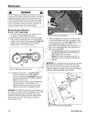
... "CHECK MOWER DRIVE BELT". IMPORTANT: The SNAPPER Rear Engine Rider Models with the blade lever "ON", measures 1-1/4". WARNING ! Engage parking brake. Too little slack may cause improper clutching, and braking could be performed: Peel back the rubber clutch/brake pedal pad and push one ferrule (B) through the hole (C) in the pedal to the "OFF" position. Pull the front frame forward until the belt spacing, with 33" decks do not require belt tension adjustment. Remove key...
... "CHECK MOWER DRIVE BELT". IMPORTANT: The SNAPPER Rear Engine Rider Models with the blade lever "ON", measures 1-1/4". WARNING ! Engage parking brake. Too little slack may cause improper clutching, and braking could be performed: Peel back the rubber clutch/brake pedal pad and push one ferrule (B) through the hole (C) in the pedal to the "OFF" position. Pull the front frame forward until the belt spacing, with 33" decks do not require belt tension adjustment. Remove key...

Operater's Manual
Page 27
... the clutch/brake cable (B) and the bottom of the housing. 7. After adjustment is not 3/4", loosen the two jam-nuts (A, Figure 40). Retest the wheel brake. DO NOT attempt any adjustments, maintenance, service or repairs with the engine running. Remove key. Remove spark plug wire from spark plug and secure away from fastest speed. The measurement should be closed securely to prevent fuel spillage. 4. E Rear Engine Rider Drive Components Service Brake / Park Brake Adjustment Test the wheel brake on this page. 2. Depress the clutch/brake pedal...
... the clutch/brake cable (B) and the bottom of the housing. 7. After adjustment is not 3/4", loosen the two jam-nuts (A, Figure 40). Retest the wheel brake. DO NOT attempt any adjustments, maintenance, service or repairs with the engine running. Remove key. Remove spark plug wire from spark plug and secure away from fastest speed. The measurement should be closed securely to prevent fuel spillage. 4. E Rear Engine Rider Drive Components Service Brake / Park Brake Adjustment Test the wheel brake on this page. 2. Depress the clutch/brake pedal...
Operater's Manual
Page 28
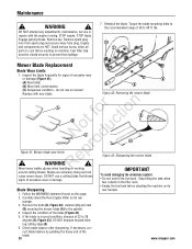
... - Engage parking brake. Reinstall the blade. R Wear heavy leather gloves when handling or working on its Blade Sharpening rear bumper. 1. DO NOT use on this page. 2. Remove key. Torque the blade mounting bolts to the recommended range of 30 to prevent fuel spillage. 7. rect blade balance by grinding the heavy end of the blade (Figure 41). 5. DO NOT attempt any adjustments, maintenance, service or repairs with new blade. STOP engine. Stop filling the tank...
... - Engage parking brake. Reinstall the blade. R Wear heavy leather gloves when handling or working on its Blade Sharpening rear bumper. 1. DO NOT use on this page. 2. Remove key. Torque the blade mounting bolts to the recommended range of 30 to prevent fuel spillage. 7. rect blade balance by grinding the heavy end of the blade (Figure 41). 5. DO NOT attempt any adjustments, maintenance, service or repairs with new blade. STOP engine. Stop filling the tank...
Operater's Manual
Page 29
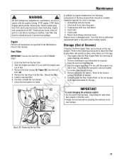
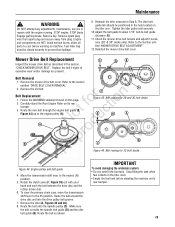
...: Belt routing for 33 inch decks Figure 44: Engine pulley and belt guide 4. Make sure the belt is inside the spindle belt guide (D) and the idler belt guide (B). Maintenance ! STOP blade. Avoid serious burns, allow 1/16" belt-to prevent fuel spillage. 9. Tighten the idler pulley bolt securely. 10. Reinstall the mower drive belt cover. Remove the old belt. Rotate the clutch yoke (F, Figure 39) out with the engine running. To clear the primary chain case, move the transmission shift lever to the Section entitled "MOWER DRIVE BELT ADJUSTMENT...
...: Belt routing for 33 inch decks Figure 44: Engine pulley and belt guide 4. Make sure the belt is inside the spindle belt guide (D) and the idler belt guide (B). Maintenance ! STOP blade. Avoid serious burns, allow 1/16" belt-to prevent fuel spillage. 9. Tighten the idler pulley bolt securely. 10. Reinstall the mower drive belt cover. Remove the old belt. Rotate the clutch yoke (F, Figure 39) out with the engine running. To clear the primary chain case, move the transmission shift lever to the Section entitled "MOWER DRIVE BELT ADJUSTMENT...
Operater's Manual
Page 32
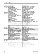
... 3. Fuel tank empty. Electric Starter 3. Water, debris or stale fuel in seat. Move choke control to proper torque. 4. Service spark plug. 6. Throttle control set improperly. Service mower blade(s). 2. Loose or missing air lift (if equipped). 3. Start Using 2. Recoil Starter 3. Faulty parking brake, blade or ignition switch. 5. Engine air pre-cleaner and or air cleaner dirty. Lumpy or frayed belt. 4. Replace pulley. 32 www.snapper.com fo tio 12. Electrical wiring harness disconnected or t c broken. 1. e 1. Charge or replace with new...
... 3. Fuel tank empty. Electric Starter 3. Water, debris or stale fuel in seat. Move choke control to proper torque. 4. Service spark plug. 6. Throttle control set improperly. Service mower blade(s). 2. Loose or missing air lift (if equipped). 3. Start Using 2. Recoil Starter 3. Faulty parking brake, blade or ignition switch. 5. Engine air pre-cleaner and or air cleaner dirty. Lumpy or frayed belt. 4. Replace pulley. 32 www.snapper.com fo tio 12. Electrical wiring harness disconnected or t c broken. 1. e 1. Charge or replace with new...
Operater's Manual
Page 33
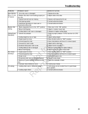
... Grass Discharge Oil Leaking PROBABLE CAUSE CORRECTIVE ACTION 1. Improper blade installed on drive disc. 3. Adjust front to the "ON" position. 2. Move throttle control to proper pressure. 15 PSI front tire & 12 PSI rear tire. 2. Verify plugs are not cracked & are in the "OFF" position. 2. Drive disc worn or damaged. 2. Mower belt slipping. 3. Adjust rubber drive disc. 3. Contact authorized dealer. 1. Sharpen or replace cutting blade. 1. Uneven tire pressure. 2. Engine speed too slow. 4. Bring to "FAST" position. 2. Adjust cutting height. 3. Move transmission shift lever...
... Grass Discharge Oil Leaking PROBABLE CAUSE CORRECTIVE ACTION 1. Improper blade installed on drive disc. 3. Adjust front to the "ON" position. 2. Move throttle control to proper pressure. 15 PSI front tire & 12 PSI rear tire. 2. Verify plugs are not cracked & are in the "OFF" position. 2. Drive disc worn or damaged. 2. Mower belt slipping. 3. Adjust rubber drive disc. 3. Contact authorized dealer. 1. Sharpen or replace cutting blade. 1. Uneven tire pressure. 2. Engine speed too slow. 4. Bring to "FAST" position. 2. Adjust cutting height. 3. Move transmission shift lever...
Operater's Manual
Page 34
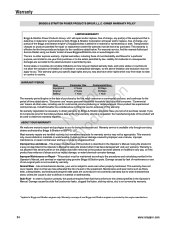
... Consumer Use Commercial Use: Equipment Engine* Battery 2 Years 2 Years 1 Year 90 Days 90 Days 1 Year r n The warranty period begins on Briggs & Stratton products. If you may not be considered as commercial use , it has been damaged will repair and/or replace, free of charge, any way, or if the R product has evidence of abuse such as filters, belts, cutting blades, and brake pads (engine brake pads are covered) are handled...
... Consumer Use Commercial Use: Equipment Engine* Battery 2 Years 2 Years 1 Year 90 Days 90 Days 1 Year r n The warranty period begins on Briggs & Stratton products. If you may not be considered as commercial use , it has been damaged will repair and/or replace, free of charge, any way, or if the R product has evidence of abuse such as filters, belts, cutting blades, and brake pads (engine brake pads are covered) are handled...


