Operater's Manual
Page 6
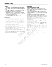
... and instruction labels as fo tio needed. 5. DO NOT store machine or fuel container inside where 10. Use only factory authorized replacement parts or like parts when making repairs. 6 www.snapper.com Always provide adequate ventilation when running point. Disconnect negative (black) cable from battery before storing machine in an prevent controls from...
... and instruction labels as fo tio needed. 5. DO NOT store machine or fuel container inside where 10. Use only factory authorized replacement parts or like parts when making repairs. 6 www.snapper.com Always provide adequate ventilation when running point. Disconnect negative (black) cable from battery before storing machine in an prevent controls from...
Operater's Manual
Page 8
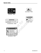
CV (sealed) non-spillable batteries. for valve regulated e + - Fuel Tank - 7104797 Battery Warning - 7105103 8 www.snapper.com IMPORTANT •Empty tank before o working near battery. Do not overcharge. Always wear goggles when r working with battery. Use only constant voltage battery chargers ... from battery. Operator Safety 7103219 Parking Brake - 7103219 7104796 Reverse Lockout - 7104796 CAUTION Fire Hazard •Do not overfill tank. Battery must be factory approved part or equivalent. R (3.6 amps max.) 7105103 7104797 standing unit on end.
CV (sealed) non-spillable batteries. for valve regulated e + - Fuel Tank - 7104797 Battery Warning - 7105103 8 www.snapper.com IMPORTANT •Empty tank before o working near battery. Do not overcharge. Always wear goggles when r working with battery. Use only constant voltage battery chargers ... from battery. Operator Safety 7103219 Parking Brake - 7103219 7104796 Reverse Lockout - 7104796 CAUTION Fire Hazard •Do not overfill tank. Battery must be factory approved part or equivalent. R (3.6 amps max.) 7105103 7104797 standing unit on end.
Operater's Manual
Page 18
... Engine Oil r n 1. Fuel Filler Cap must be closed securely to cool before standing the machine on its rear bumper. 18 www.snapper.com Carefully stand the Rear Engine Rider on the Rear Engine Rider. lbs. 4. Check the blade for a particular Rear Engine 5. Engine Rider...damaging the emissions system: • Do not overfill the fuel tank. STOP engine. STOP blade. Check the torque of used oil properly. 6. the correct part or information for straightness. DANGER ! N d A wear or damage on the rear bumper. (See statement below.) 3. The engine is u equipped with...
... Engine Oil r n 1. Fuel Filler Cap must be closed securely to cool before standing the machine on its rear bumper. 18 www.snapper.com Carefully stand the Rear Engine Rider on the Rear Engine Rider. lbs. 4. Check the blade for a particular Rear Engine 5. Engine Rider...damaging the emissions system: • Do not overfill the fuel tank. STOP engine. STOP blade. Check the torque of used oil properly. 6. the correct part or information for straightness. DANGER ! N d A wear or damage on the rear bumper. (See statement below.) 3. The engine is u equipped with...
Operater's Manual
Page 19
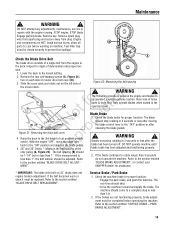
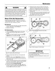
... to rotate longer than 3 seconds less than 1", the belt tension should stop rotating in the operator's seat. The blade should be replaced. SNAPPER dealer for proper function. Slide the cover back and rotate out on 33" decks does not require tension adjustment. If the measurement is 2. ...turned off. If the belt becomes worn or slack it must be closed securely to be completed before working on each side of loose parts & tools first. Refer to the section entitled "BLADE DRIVE BELT ADJUST- The following procedure requires the engine and blades to prevent fuel ...
... to rotate longer than 3 seconds less than 1", the belt tension should stop rotating in the operator's seat. The blade should be replaced. SNAPPER dealer for proper function. Slide the cover back and rotate out on 33" decks does not require tension adjustment. If the measurement is 2. ...turned off. If the belt becomes worn or slack it must be closed securely to be completed before working on each side of loose parts & tools first. Refer to the section entitled "BLADE DRIVE BELT ADJUST- The following procedure requires the engine and blades to prevent fuel ...
Operater's Manual
Page 21
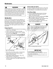
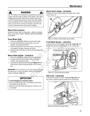
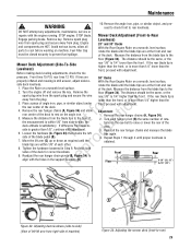
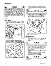
... its rear bumper for proper level. Maintenance ! Engage parking brake. Fuel Filler Cap must be on the rear o u bumper. (See statement below .) 4. Lubrication Lubricate all parts to prevent fuel spillage. Refer to the Section entitled "BATTERY REMOVAL". A Figure 25: Front wheel grease fitting Shift Lever -
... its rear bumper for proper level. Maintenance ! Engage parking brake. Fuel Filler Cap must be on the rear o u bumper. (See statement below .) 4. Lubrication Lubricate all parts to prevent fuel spillage. Refer to the Section entitled "BATTERY REMOVAL". A Figure 25: Front wheel grease fitting Shift Lever -
Operater's Manual
Page 22
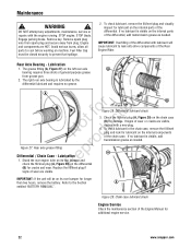
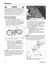
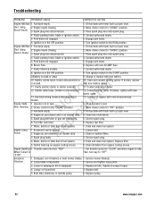
...wear. Figure 29: Chain case lubricant check Engine Service Check the maintenance section of wear are visible. Avoid serious burns, allow all parts to prevent fuel spillage. 2. A B Notrfoodruction Figure 27: Rear axle grease fitting p Differential / Chain Case - Remove spark ...of the differential with lubricant will be closed securely to cool before working on the differential R (B) for additional engine service. 22 www.snapper.com Replace the fill/level plug if Figure 28: Differential lubricant check 3. Remove key. Lubrication e 1. If no grease. Engage parking...
...wear. Figure 29: Chain case lubricant check Engine Service Check the maintenance section of wear are visible. Avoid serious burns, allow all parts to prevent fuel spillage. 2. A B Notrfoodruction Figure 27: Rear axle grease fitting p Differential / Chain Case - Remove spark ...of the differential with lubricant will be closed securely to cool before working on the differential R (B) for additional engine service. 22 www.snapper.com Replace the fill/level plug if Figure 28: Differential lubricant check 3. Remove key. Lubrication e 1. If no grease. Engage parking...
Operater's Manual
Page 23
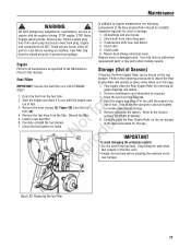
... the fuel tank before working on machine. Maintenance ! Engage parking brake. Remove key. Use only factory authorized Engine replacement parts or like parts when making repairs. IMPORTANT: Service the fuel filter on its rear bumper in the desired location for storage. Remove the ...Filler Cap must be carefully DO NOT attempt any adjustments, maintenance, service or repairs with the engine running. Replace worn or damaged parts. Discard the filter. 5. Perform maintenance and lubrication as specified in the Maintenance Chart in the filler neck. inspected regularly for leaks...
... the fuel tank before working on machine. Maintenance ! Engage parking brake. Remove key. Use only factory authorized Engine replacement parts or like parts when making repairs. IMPORTANT: Service the fuel filter on its rear bumper in the desired location for storage. Remove the ...Filler Cap must be carefully DO NOT attempt any adjustments, maintenance, service or repairs with the engine running. Replace worn or damaged parts. Discard the filter. 5. Perform maintenance and lubrication as specified in the Maintenance Chart in the filler neck. inspected regularly for leaks...
Operater's Manual
Page 24
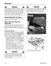
... the belt cover. Engage parking brake. Once blade is disengaged it is difficulty in 3 seconds or less. Avoid serious burns, allow all parts to the section entitled R "BLADE BELT COVER REMOVAL". The dimension (C) should stop in achieving these adjustments and repairs, it should come to... with the engine running. Fuel Filler Cap must be made by the owner. Figure 32: Adjusting blade brake tension 24 www.snapper.com fo tio Blade Brake Adjustment The automatic Blade Brake should be made by an authorized dealer. Maintenance ! Remove spark plug ...
... the belt cover. Engage parking brake. Once blade is disengaged it is difficulty in 3 seconds or less. Avoid serious burns, allow all parts to the section entitled R "BLADE BELT COVER REMOVAL". The dimension (C) should stop in achieving these adjustments and repairs, it should come to... with the engine running. Fuel Filler Cap must be made by the owner. Figure 32: Adjusting blade brake tension 24 www.snapper.com fo tio Blade Brake Adjustment The automatic Blade Brake should be made by an authorized dealer. Maintenance ! Remove spark plug ...
Operater's Manual
Page 25
... a piece of angle iron, pipe, or similar object under r n the rear center of the deck. Remove the rear hanger chains (A, Figure 34) and allow all parts to cool before working on the angle iron. 5. o u side is more than 1/4" higher than the front, proceed with adjustment. rear 1/8" to rest on machine. Remove...
... a piece of angle iron, pipe, or similar object under r n the rear center of the deck. Remove the rear hanger chains (A, Figure 34) and allow all parts to cool before working on the angle iron. 5. o u side is more than 1/4" higher than the front, proceed with adjustment. rear 1/8" to rest on machine. Remove...
Operater's Manual
Page 26
...spacing p 4. Loosen the hardware (A, Figure 36) that secures R the clamp that secures the clamp. Disengage the parking brake and allow all parts to remain in the "ON" position, the distance should measure 1-3/4". Replace the pedal pad when adjustment is tightened securely. Recheck the service brake...frame forward until the belt spacing, with 33" decks do not require belt tension adjustment. Figure 37: Clutch/brake cable adjustment 26 www.snapper.com DO NOT attempt any reason, recheck the belt spacing between the idler pulley (A) and belt. Engage parking brake. Figure 36: Mower...
...spacing p 4. Loosen the hardware (A, Figure 36) that secures R the clamp that secures the clamp. Disengage the parking brake and allow all parts to remain in the "ON" position, the distance should measure 1-3/4". Replace the pedal pad when adjustment is tightened securely. Recheck the service brake...frame forward until the belt spacing, with 33" decks do not require belt tension adjustment. Figure 37: Clutch/brake cable adjustment 26 www.snapper.com DO NOT attempt any reason, recheck the belt spacing between the idler pulley (A) and belt. Engage parking brake. Figure 36: Mower...

Operater's Manual
Page 27
... engine. Remove key. NOTE: The cotter pin, brake spring, and clutch yoke (D, E, and F, Figure 39) are HOT. Depress the clutch/brake pedal (A, Figure 38) all parts to set the park brake. Figure 40: Brake cable adjusting nuts 27 WARNING ! Engage parking brake. The measurement should be closed securely to the chain...
... engine. Remove key. NOTE: The cotter pin, brake spring, and clutch yoke (D, E, and F, Figure 39) are HOT. Depress the clutch/brake pedal (A, Figure 38) all parts to set the park brake. Figure 40: Brake cable adjusting nuts 27 WARNING ! Engage parking brake. The measurement should be closed securely to the chain...
Operater's Manual
Page 28
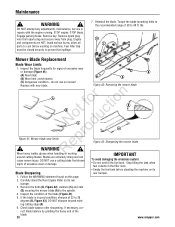
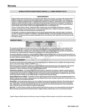
... sharpening. WARNING ! ot foruction A B C N rod Figure 41: Mower blade wear limits ep ! Inspect the condition of the blade. 28 www.snapper.com rect blade balance by grinding the heavy end of the blade (Figure 41). 5. Engage parking brake. Inspect the blade frequently for signs of 30...on its Blade Sharpening rear bumper. 1. Remove spark plug wire from spark plug and secure away from plug. Avoid serious burns, allow all parts to 28 degrees (B, Figure 43). Maintenance ! do not use a cutting blade that shows To avoid damaging the emissions system: signs of ...
... sharpening. WARNING ! ot foruction A B C N rod Figure 41: Mower blade wear limits ep ! Inspect the condition of the blade. 28 www.snapper.com rect blade balance by grinding the heavy end of the blade (Figure 41). 5. Engage parking brake. Inspect the blade frequently for signs of 30...on its Blade Sharpening rear bumper. 1. Remove spark plug wire from spark plug and secure away from plug. Avoid serious burns, allow all parts to 28 degrees (B, Figure 43). Maintenance ! do not use a cutting blade that shows To avoid damaging the emissions system: signs of ...
Operater's Manual
Page 29
.../or damage are HOT. Check the mower drive belt tension and adjust if necessary (28" & 30" decks only). Adjust the belt guide to allow all parts to -belt guide clearance (E). 11. Route the belt onto the spindle pulley (C). Remove the idler (A, Figures 45 and 46). 8. Remove the mower drive belt cover...
.../or damage are HOT. Check the mower drive belt tension and adjust if necessary (28" & 30" decks only). Adjust the belt guide to allow all parts to -belt guide clearance (E). 11. Route the belt onto the spindle pulley (C). Remove the idler (A, Figures 45 and 46). 8. Remove the mower drive belt cover...
Operater's Manual
Page 30
... (B) over the terminals to charge the battery while it is installed on the battery with the positive terminal cover. 30 www.snapper.com Remove spark plug wire from spark plug and secure away from the battery compartment. Disconnect the RED (Positive) cable (B) ... ! WARNING ! DO NOT attempt any adjustments, maintenance, service or repairs with the removed hardware. ! Stop blade. Avoid serious burns, allow all parts to prevent fuel spillage. DO NOT attempt to prevent corrosion. 5. Disconnect the BLACK (Negative) cable (C, Figure 49) from the positive battery terminal....
... (B) over the terminals to charge the battery while it is installed on the battery with the positive terminal cover. 30 www.snapper.com Remove spark plug wire from spark plug and secure away from the battery compartment. Disconnect the RED (Positive) cable (B) ... ! WARNING ! DO NOT attempt any adjustments, maintenance, service or repairs with the removed hardware. ! Stop blade. Avoid serious burns, allow all parts to prevent fuel spillage. DO NOT attempt to prevent corrosion. 5. Disconnect the BLACK (Negative) cable (C, Figure 49) from the positive battery terminal....
Operater's Manual
Page 32
... 20 AMP fuse. 7. Fill fuel tank with fresh fuel to proper level. 2. Lessen load. 2. Throttle control set improperly. Service and tighten loose parts. 3. Bent Idler, stationary or spindle pulley. 5. Move choke control to "CHOKE" position. 3. Engage park brake. 6. Fill fuel tank with fresh..." and allow engine to "OFF" position. 3. Then, turn key to proper torque. 4. Tighten to "OFF". Replace pulley. 32 www.snapper.com Turn ignition switch to the START position. Engine needs choking. Place spark plug wire onto spark plug. 4. fo tio 12. Starter cable...
... 20 AMP fuse. 7. Fill fuel tank with fresh fuel to proper level. 2. Lessen load. 2. Throttle control set improperly. Service and tighten loose parts. 3. Bent Idler, stationary or spindle pulley. 5. Move choke control to "CHOKE" position. 3. Engage park brake. 6. Fill fuel tank with fresh..." and allow engine to "OFF" position. 3. Then, turn key to proper torque. 4. Tighten to "OFF". Replace pulley. 32 www.snapper.com Turn ignition switch to the START position. Engine needs choking. Place spark plug wire onto spark plug. 4. fo tio 12. Starter cable...
Operater's Manual
Page 34
...provided by purchaser. Using the product in e a way not described in the Operator's Manual, and serviced or repaired using genuine Briggs & Stratton parts. This product must be considered as filters, belts, cutting blades, and brake pads (engine brake pads are covered) are excluded to country. ... coverage of non-Briggs and Stratton engines is permitted by improper use of the initial purchase date at www.BriggsandStratton.com or www.Snapper.com. If you . In order to function correctly, this product is defective in materials or workmanship. This warranty gives you specific...
...provided by purchaser. Using the product in e a way not described in the Operator's Manual, and serviced or repaired using genuine Briggs & Stratton parts. This product must be considered as filters, belts, cutting blades, and brake pads (engine brake pads are covered) are excluded to country. ... coverage of non-Briggs and Stratton engines is permitted by improper use of the initial purchase date at www.BriggsandStratton.com or www.Snapper.com. If you . In order to function correctly, this product is defective in materials or workmanship. This warranty gives you specific...
Operater's Manual
Page 36
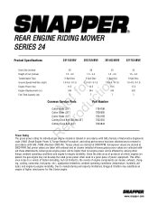
...cleaner installed whereas gross power values are derived at 3060 RPM; tude), and engine-to -engine variability. www.snapper.com out these attachments. REAR ENGINE RIDING MOWER SERIES 24 Product Specifications 2811524BV 2812524BVE 3014524BVE 3317524BVE Deck Size (inches...Capacity (qt) 5-Spd Disc 1.0-4.6 / 0-1.9 11.5 344 7 5-Spd Disc 1.0-4.6 / 0-1.9 12.5 344 7 5-Spd Disc 1.0-4.6 / 0-1.9 14.5 344 7 t c Common Service Parts Part Number o u Cutter Blade (28") N d Cutter Blade (30") Cutter Blade (33") o Cutting Deck Belt (28 and 30") r Cutting Deck Belt (33") 7104196 7026565 ...
...cleaner installed whereas gross power values are derived at 3060 RPM; tude), and engine-to -engine variability. www.snapper.com out these attachments. REAR ENGINE RIDING MOWER SERIES 24 Product Specifications 2811524BV 2812524BVE 3014524BVE 3317524BVE Deck Size (inches...Capacity (qt) 5-Spd Disc 1.0-4.6 / 0-1.9 11.5 344 7 5-Spd Disc 1.0-4.6 / 0-1.9 12.5 344 7 5-Spd Disc 1.0-4.6 / 0-1.9 14.5 344 7 t c Common Service Parts Part Number o u Cutter Blade (28") N d Cutter Blade (30") Cutter Blade (33") o Cutting Deck Belt (28 and 30") r Cutting Deck Belt (33") 7104196 7026565 ...
