Operater's Manual
Page 4
...% watchful care of a responsible adult other hidden hazards. DO NOT put your satisfaction, contact Customer Service (1-800-935-2967 or www.snapper.com). Data indicates that can result in this manual. WARNING: This powerful cutting machine is doubtful. 13. DO NOT 1. USE EXTRA... the 7. Always keep the machine in a large percentage of children. involved in gear when going uphill or tires lose traction, turn over accidents, which might impair vision, dexterity or judgment. Protection for holes and other than the operator. Children who understand these affect...
...% watchful care of a responsible adult other hidden hazards. DO NOT put your satisfaction, contact Customer Service (1-800-935-2967 or www.snapper.com). Data indicates that can result in this manual. WARNING: This powerful cutting machine is doubtful. 13. DO NOT 1. USE EXTRA... the 7. Always keep the machine in a large percentage of children. involved in gear when going uphill or tires lose traction, turn over accidents, which might impair vision, dexterity or judgment. Protection for holes and other than the operator. Children who understand these affect...
Operater's Manual
Page 5
... clothing, change clothing immediate- DO NOT refuel the machine indoors. 5. Always place the contain- Set 12. Operate machine only in prepa- mower to cool before turning. 10. Mount and dismount machine from the vehicle or R trailer and refuel it on feet rests or pedal(s). 10. Only use accessories approved by the...
... clothing, change clothing immediate- DO NOT refuel the machine indoors. 5. Always place the contain- Set 12. Operate machine only in prepa- mower to cool before turning. 10. Mount and dismount machine from the vehicle or R trailer and refuel it on feet rests or pedal(s). 10. Only use accessories approved by the...
Operater's Manual
Page 11
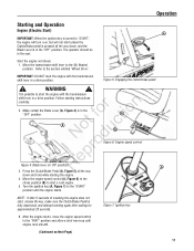
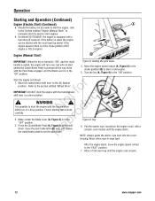
Operation Starting and Operation Engine (Electric Start) IMPORTANT: When the ignition key is turned to "START", the engine will turn over, but will not start unless the Clutch/Brake pedal is pressed all the way down , and the Blade Lever is possible to the ...6. WARNING ! Move the engine speed control (A, Figure 6) to the choke position (B) to the "FAST" position and allow a brief warm-up until the engine starts. Turn the ignition key (A, Figure 7) to start the engine with the transmission shift lever in the seat. Refer to the (N) Neutral position. Press the Clutch/Brake...
Operation Starting and Operation Engine (Electric Start) IMPORTANT: When the ignition key is turned to "START", the engine will turn over, but will not start unless the Clutch/Brake pedal is pressed all the way down , and the Blade Lever is possible to the ...6. WARNING ! Move the engine speed control (A, Figure 6) to the choke position (B) to the "FAST" position and allow a brief warm-up until the engine starts. Turn the ignition key (A, Figure 7) to start the engine with the transmission shift lever in the seat. Refer to the (N) Neutral position. Press the Clutch/Brake...
Operater's Manual
Page 12
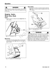
... cold engine. 5. fo tio IMPORTANT: DO NOT start the engine with a smooth, even motion until the engine runs smooth. 12 www.snapper.com ro 2. Pull the starter rope, located on the engine recoil, with the transmission shift lever in a drive position. If the battery...possible to set the park brake. A Figure 9: Key 6. Follow starting instructions carefully. Make certain the Blade Lever (A, Figure 4) is pulled, the engine will turn over , and release R the clutch/brake pedal to start unless the Clutch/Brake Pedal is in a drive position. p 3. ot c ! WARNING ! On...
... cold engine. 5. fo tio IMPORTANT: DO NOT start the engine with a smooth, even motion until the engine runs smooth. 12 www.snapper.com ro 2. Pull the starter rope, located on the engine recoil, with the transmission shift lever in a drive position. If the battery...possible to set the park brake. A Figure 9: Key 6. Follow starting instructions carefully. Make certain the Blade Lever (A, Figure 4) is pulled, the engine will turn over , and release R the clutch/brake pedal to start unless the Clutch/Brake Pedal is in a drive position. p 3. ot c ! WARNING ! On...
Operater's Manual
Page 14
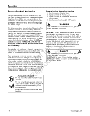
...seconds, the blade brake must be adjusted. Figure 15: Stopping the mower blade ! Shift to r apply the brake. Stop the mower blade by turning the key (A, Figure 13) to 'Off' N du Wheel Drive 1. Once blade is adjusted and functioning properly. Stop motion of the Rear ... down to neutral and engage park brake. WARNING ! Remove key. RepA Figure 14: Engaging the clutch/brake pedal 14 www.snapper.com B A r n A ot fo ctio Figure 13: Turning key to the "OFF" position. Operation ! Engine, Wheel Drive, Blade Engine 1. DO NOT leave the machine with the engine...
...seconds, the blade brake must be adjusted. Figure 15: Stopping the mower blade ! Shift to r apply the brake. Stop the mower blade by turning the key (A, Figure 13) to 'Off' N du Wheel Drive 1. Once blade is adjusted and functioning properly. Stop motion of the Rear ... down to neutral and engage park brake. WARNING ! Remove key. RepA Figure 14: Engaging the clutch/brake pedal 14 www.snapper.com B A r n A ot fo ctio Figure 13: Turning key to the "OFF" position. Operation ! Engine, Wheel Drive, Blade Engine 1. DO NOT leave the machine with the engine...
Operater's Manual
Page 16
... have been given rides on machine (even with the blade turn blade off. This riding mower has a Reverse Lockout Mechanism. must be turned off ) or in reverse. To return to your local Snapper dealer for proper ate blades in yard when mowing. 16 www.snapper.com r n We realize that require quicker shifting to Reverse...
... have been given rides on machine (even with the blade turn blade off. This riding mower has a Reverse Lockout Mechanism. must be turned off ) or in reverse. To return to your local Snapper dealer for proper ate blades in yard when mowing. 16 www.snapper.com r n We realize that require quicker shifting to Reverse...
Operater's Manual
Page 19
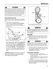
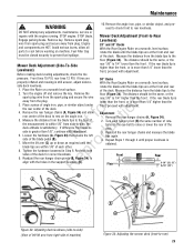
... caution. Check the blade brake for tion A t c B No odu Figure 21: Removing the drive belt cover r 4. Blades must be closed securely to the lowest setting. 2. SNAPPER dealer for assistance. * IMPORTANT: The blade drive belt on machine. Service Brake / Park Brake 1. The rear tires should ! PARK BRAKE ADJUSTMENT". 19 With the engine... signs of Figure 22: Measuring the belt spacing the mower deck. The machine should come to the "OFF" position or after the blade has been turned off.
... caution. Check the blade brake for tion A t c B No odu Figure 21: Removing the drive belt cover r 4. Blades must be closed securely to the lowest setting. 2. SNAPPER dealer for assistance. * IMPORTANT: The blade drive belt on machine. Service Brake / Park Brake 1. The rear tires should ! PARK BRAKE ADJUSTMENT". 19 With the engine... signs of Figure 22: Measuring the belt spacing the mower deck. The machine should come to the "OFF" position or after the blade has been turned off.
Operater's Manual
Page 25
... the floor (Figure 34). Front tires 15 PSI, rear tires 12 PSI. Place the Rider on a smooth, level surface, side deck levelness. of the deck. Turn the engine off and remove the key. r 8. p 9. If the rear blade tip is lower than the front, or is satisfactory. Front Floor X Rear X-1/8" (... chains (A, Figure 34) and allow all parts to rest on the eye-bolt to -Rear Engage parking brake. Recheck both sides of the deck. 3. Turn each other. STOP blade. o u side is obtained. Mower Deck Adjustment (Front-to raise or lower the rear of the deck for correct levelness. Remove...
... the floor (Figure 34). Front tires 15 PSI, rear tires 12 PSI. Place the Rider on a smooth, level surface, side deck levelness. of the deck. Turn the engine off and remove the key. r 8. p 9. If the rear blade tip is lower than the front, or is satisfactory. Front Floor X Rear X-1/8" (... chains (A, Figure 34) and allow all parts to rest on the eye-bolt to -Rear Engage parking brake. Recheck both sides of the deck. 3. Turn each other. STOP blade. o u side is obtained. Mower Deck Adjustment (Front-to raise or lower the rear of the deck for correct levelness. Remove...
Operater's Manual
Page 32
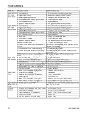
...missing air lift (if equipped). 3. Spark plug wire disconnected. 4. Place spark plug wire onto spark plug. 4. Ignition is in the OFF position. 1. Turn ignition switch to proper level. 2. Engine needs choking. Spark plug wire disconnected. 4. Fill fuel tank with fresh fuel to "CHOKE" position. 3. Engage park...debris or stale fuel in the OFF position. 5. Contact authorized dealer. 12. Debris build up on engine. 2. Replace pulley. 32 www.snapper.com Start Using 2. Clean and connect battery cables. Clean free of balance or bent mower blades. 1. Drain and clean fuel system. ...
...missing air lift (if equipped). 3. Spark plug wire disconnected. 4. Place spark plug wire onto spark plug. 4. Ignition is in the OFF position. 1. Turn ignition switch to proper level. 2. Engine needs choking. Spark plug wire disconnected. 4. Fill fuel tank with fresh fuel to "CHOKE" position. 3. Engage park...debris or stale fuel in the OFF position. 5. Contact authorized dealer. 12. Debris build up on engine. 2. Replace pulley. 32 www.snapper.com Start Using 2. Clean and connect battery cables. Clean free of balance or bent mower blades. 1. Drain and clean fuel system. ...
