Operation Manual
Page 8
...related to the digital VTR. Chapter 7 Maintenance Explains basic VTR maintenance. Appendixes ® Specifications Gives general specifications, and the principal specifications of the controls and other parts. Chapter 4 Recording Explains preparation for playback, normal speed playback, jog and shuttle playback, capstan override playback, and DMC playback. Index 6 About This Manual Chapter 1 Overview Describes the principal features and functions of videocassettes. Chapter 5 Playback Describes preparation for recording, time code settings, and basic recording operations. Chapter...
...related to the digital VTR. Chapter 7 Maintenance Explains basic VTR maintenance. Appendixes ® Specifications Gives general specifications, and the principal specifications of the controls and other parts. Chapter 4 Recording Explains preparation for playback, normal speed playback, jog and shuttle playback, capstan override playback, and DMC playback. Index 6 About This Manual Chapter 1 Overview Describes the principal features and functions of videocassettes. Chapter 5 Playback Describes preparation for recording, time code settings, and basic recording operations. Chapter...
Operation Manual
Page 13
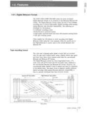
... dynamic tracking heads ® New auto tracking system These enables the 120 minutes or more recording with 6 helical tracks, using the L-size cassette), while the cassette size of the available recording area to the conventional Betacam and Betacam SP format. r -l- I I a aa e -ia i-riaa I s I I s i-s -, i e I 1 i -I - !-- The Digital Betacam format has three longitudinal tracks, CTL track, time code (LTC) track and the cue audio track, identical to achieve high-quality digital recording while keeping analog Betacam tape playback...
... dynamic tracking heads ® New auto tracking system These enables the 120 minutes or more recording with 6 helical tracks, using the L-size cassette), while the cassette size of the available recording area to the conventional Betacam and Betacam SP format. r -l- I I a aa e -ia i-riaa I s I I s i-s -, i e I 1 i -I - !-- The Digital Betacam format has three longitudinal tracks, CTL track, time code (LTC) track and the cue audio track, identical to achieve high-quality digital recording while keeping analog Betacam tape playback...
Operation Manual
Page 16
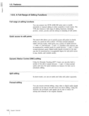
... can connect two DVW-A500/500 series units to the original channels. 1-6 Chapter 1 Overview Digital audio signals recorded on the tape as the edit source for mixing and returned to enable automatic or manual editing in shuttle mode, at speeds between -1 and + 3 times normal playback speed. Dynamic Motion Control (DMC) editing Using the Dynamic Tracking (DT° ) head, you can also be monitored in variable mode at a speed between -1 and + 3 times normal speed...
... can connect two DVW-A500/500 series units to the original channels. 1-6 Chapter 1 Overview Digital audio signals recorded on the tape as the edit source for mixing and returned to enable automatic or manual editing in shuttle mode, at speeds between -1 and + 3 times normal playback speed. Dynamic Motion Control (DMC) editing Using the Dynamic Tracking (DT° ) head, you can also be monitored in variable mode at a speed between -1 and + 3 times normal speed...
Operation Manual
Page 26
... the audio level meters. Adjust the volume level with the setup menu. O POWER switch Set the switch to ON to monitor the audio during recording, playback and editing. You can be used is below the minimum level, the lowermost segment will light. Upon pushing in 0.25 dB steps. Setup Menu" in the installation Manual. • PB (playback) level controls Independently adjust the audio playback levels for an input signal of channels 1 to be in E-E mode...
... the audio level meters. Adjust the volume level with the setup menu. O POWER switch Set the switch to ON to monitor the audio during recording, playback and editing. You can be used is below the minimum level, the lowermost segment will light. Upon pushing in 0.25 dB steps. Setup Menu" in the installation Manual. • PB (playback) level controls Independently adjust the audio playback levels for an input signal of channels 1 to be in E-E mode...
Operation Manual
Page 27
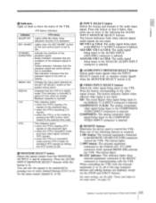
.... Lights when the KEY INHIBIT switch on the playback tape. ® when the VTR is record/E-E mode and input video signal contains VITC signals. ® when the VTR is in operation. Indicate the condition of the following the AUDIO INPUT/MONITOR SELECT buttons. Red indicator: indicates that the playback signal has some failures but is selected. ® REMOTE buttons Determine the device used to the COMPOSITE VIDEO INPUT...
.... Lights when the KEY INHIBIT switch on the playback tape. ® when the VTR is record/E-E mode and input video signal contains VITC signals. ® when the VTR is in operation. Indicate the condition of the following the AUDIO INPUT/MONITOR SELECT buttons. Red indicator: indicates that the playback signal has some failures but is selected. ® REMOTE buttons Determine the device used to the COMPOSITE VIDEO INPUT...
Operation Manual
Page 31
... here. O EJECT button Ejects the cassette. F FWD (fast forward) button Fast forwards the tape. In stop mode). O PLAY button Starts playback. Pressing the EDIT button while the VTR is set to "1-10. Holding down the EDIT button during recording or manual editing places the VTR in the VIDEO INPUT and REF mode respectively. Setup Menu" in the time counter display. • REW (rewind) button Rewinds the tape. Resets the display when CTL codes appear in the Installation Manual. Pressing...
... here. O EJECT button Ejects the cassette. F FWD (fast forward) button Fast forwards the tape. In stop mode). O PLAY button Starts playback. Pressing the EDIT button while the VTR is set to "1-10. Holding down the EDIT button during recording or manual editing places the VTR in the VIDEO INPUT and REF mode respectively. Setup Menu" in the time counter display. • REW (rewind) button Rewinds the tape. Resets the display when CTL codes appear in the Installation Manual. Pressing...
Operation Manual
Page 35
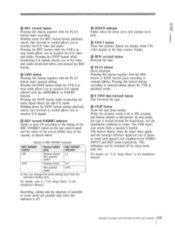
... the tape currently being recorded onto or read from the tape by the built-in hours, minutes, seconds and frames, as follows, according to the setting of these indicators lights to the setting of the error codes ("Error-XX') displayed in the time code currently being recorded onto or read from the tape. e COUNTER buttons Press one of the buttons corresponding to the type of Parts and Controls 2-13...
... the tape currently being recorded onto or read from the tape by the built-in hours, minutes, seconds and frames, as follows, according to the setting of these indicators lights to the setting of the error codes ("Error-XX') displayed in the time code currently being recorded onto or read from the tape. e COUNTER buttons Press one of the buttons corresponding to the type of Parts and Controls 2-13...

Operation Manual
Page 37
... inhibits recording, editing and the selection of assemble or insert edit mode. Setup Menu" in the Installation Manual. MANUAL: To manually adjust the black level using the BLACK LEVEL control. O KEY INHIBIT switch Setting this switch to ON turns on the REC INHIBIT indicator on the KEY INHIBIT indicator of the upper control panel and inhibits all or some key inputs of the REMOTE, VIDEO INPUT SELECT, AUDIO INPUT/MONITOR SELECT buttons...
... inhibits recording, editing and the selection of assemble or insert edit mode. Setup Menu" in the Installation Manual. MANUAL: To manually adjust the black level using the BLACK LEVEL control. O KEY INHIBIT switch Setting this switch to ON turns on the REC INHIBIT indicator on the KEY INHIBIT indicator of the upper control panel and inhibits all or some key inputs of the REMOTE, VIDEO INPUT SELECT, AUDIO INPUT/MONITOR SELECT buttons...
Operation Manual
Page 38
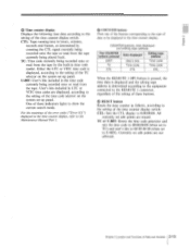
... during playback. However, optimum composite signal frequency response can be adjusted, regardless of Digital Betacam tape on which is no phase shift (H-shift) of 4-field color frame. Optimum composite frequency response is kept and there is used . Set to the decoded SC phase or the color frame ID, which component source is recorded, picture shift control is used . INT: The time code...
... during playback. However, optimum composite signal frequency response can be adjusted, regardless of Digital Betacam tape on which is no phase shift (H-shift) of 4-field color frame. Optimum composite frequency response is kept and there is used . Set to the decoded SC phase or the color frame ID, which component source is recorded, picture shift control is used . INT: The time code...
Operation Manual
Page 40
... factory set to FREE RUN. • DF/NDF (drop frame/non drop frame) switch (for Betacam playback. For details of the VTR, the time code advances as long as the VTR is powered on the lower control panel is disabled for DVW-A500/500 only) Selects whether the time code generator and CTL, counter advance in the Installation Manual. FREE RUN: Regardless of the operation mode of...
... factory set to FREE RUN. • DF/NDF (drop frame/non drop frame) switch (for Betacam playback. For details of the VTR, the time code advances as long as the VTR is powered on the lower control panel is disabled for DVW-A500/500 only) Selects whether the time code generator and CTL, counter advance in the Installation Manual. FREE RUN: Regardless of the operation mode of...
Operation Manual
Page 44
... format digital audio signals. Used when you edit using the control panel as a remote controller. • REMOTE 1-IN (9P)/OUT (9P) connectors (D-sub 9-pin) Connect to the TIME CODE IN connector. 6) TIME CODE IN connector (XLR-3-31) When recording a time code supplied from /to enable adjustment of the volume level with the VTR. For details, refer to the Installation Manual. © AUDIO OUTPUT (AES/EBU) connectors (XLR-3-32) Output a maximum of two lines (four channels: channels...
... format digital audio signals. Used when you edit using the control panel as a remote controller. • REMOTE 1-IN (9P)/OUT (9P) connectors (D-sub 9-pin) Connect to the TIME CODE IN connector. 6) TIME CODE IN connector (XLR-3-31) When recording a time code supplied from /to enable adjustment of the volume level with the VTR. For details, refer to the Installation Manual. © AUDIO OUTPUT (AES/EBU) connectors (XLR-3-32) Output a maximum of two lines (four channels: channels...
Operation Manual
Page 56
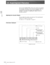
... time code reader (for DVW-A500/500 only) VITC field T C R 2 3 5 9L 4 0 ES H U T T L E S T 0 Control VTR display 8 L L 0 Operation mode Displayed information 3-12 Chapter 3 Setting Up the VTR For details, see "3-3. Setup Menu" on the signals output from the SERIAL V/A OUTPUT 4 (SUPER) or COMPOSITE VIDEO OUTPUT 3 (SUPER) connector. Adjusting the character display You can adjust the position, size and type of time code generator (for DVW-A500/500 only) 0 Drop frame mode of the superimposed characters by using the setup menu...
... time code reader (for DVW-A500/500 only) VITC field T C R 2 3 5 9L 4 0 ES H U T T L E S T 0 Control VTR display 8 L L 0 Operation mode Displayed information 3-12 Chapter 3 Setting Up the VTR For details, see "3-3. Setup Menu" on the signals output from the SERIAL V/A OUTPUT 4 (SUPER) or COMPOSITE VIDEO OUTPUT 3 (SUPER) connector. Adjusting the character display You can adjust the position, size and type of time code generator (for DVW-A500/500 only) 0 Drop frame mode of the superimposed characters by using the setup menu...
Operation Manual
Page 59
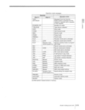
...off mode Tape tension released Stop mode Fast forward mode Rewind mode Pause mode Preroll mode Playback mode (servo unlocked) Playback mode (servo locked) Capstan override mode or program play mode Record mode (servo unlocked) Record mode (servo locked) Edit mode (servo unlocked) Edit mode (servo locked) A still picture in jog mode Jog mode in forward direction Jog mode in reverse direction Shuttle mode Variable mode DMC playback mode Preview in DMC edit mode DMC edit mode DMC initial speed setting Speed setting for program play Preview mode Automatic editing mode Review mode a) Initial speed...
...off mode Tape tension released Stop mode Fast forward mode Rewind mode Pause mode Preroll mode Playback mode (servo unlocked) Playback mode (servo locked) Capstan override mode or program play mode Record mode (servo unlocked) Record mode (servo locked) Edit mode (servo unlocked) Edit mode (servo locked) A still picture in jog mode Jog mode in forward direction Jog mode in reverse direction Shuttle mode Variable mode DMC playback mode Preview in DMC edit mode DMC edit mode DMC initial speed setting Speed setting for program play Preview mode Automatic editing mode Review mode a) Initial speed...
Operation Manual
Page 72
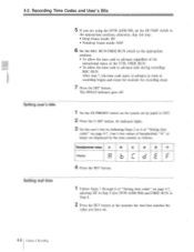
... as follows. Its indicator lights. 3 Set the user's bits by the time counter as recording begins and stops the moment the recording stops. 7 Press the SET button. Hexadecimal value A B C D E F Display •raI 1 / I 1® I _a / I r r a- / 4 Press the SET button. 1 Follow Steps 1 through 6 of "Setting time codes" on page 4-7, selecting DF in Step 5 (for DVW-A500/500) and FREE RUN in Step 6. 2 Press the SET button at the moment the...
... as follows. Its indicator lights. 3 Set the user's bits by the time counter as recording begins and stops the moment the recording stops. 7 Press the SET button. Hexadecimal value A B C D E F Display •raI 1 / I 1® I _a / I r r a- / 4 Press the SET button. 1 Follow Steps 1 through 6 of "Setting time codes" on page 4-7, selecting DF in Step 5 (for DVW-A500/500) and FREE RUN in Step 6. 2 Press the SET button at the moment the...
Operation Manual
Page 122
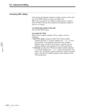
.... To control DT VTRs When using a dynamic tracking VTR as a player, note the following. VAR mode: pressing the VAR button enables noiseless playback O_ at 12 speeds ranging from -1 to + 3 times normal speed. Advanced Editing Executing DMC editing After storing the playback speed(s) in memory preview mode, press the AUTO EDIT button to + 3 times normal speed. To confirm the results of the edit Press the REVIEW button. If the playback speed exceed...
.... To control DT VTRs When using a dynamic tracking VTR as a player, note the following. VAR mode: pressing the VAR button enables noiseless playback O_ at 12 speeds ranging from -1 to + 3 times normal speed. Advanced Editing Executing DMC editing After storing the playback speed(s) in memory preview mode, press the AUTO EDIT button to + 3 times normal speed. To confirm the results of the edit Press the REVIEW button. If the playback speed exceed...
Operation Manual
Page 147
... is possible only on the tape's video track. A high head-to-tape velocity makes it possible to use part of previously recorded scenes. Bridging connection A connection that correspond to pass through two connectors: CH 1/2 and CH 3/4. Two audio channels are newly recorded. Assemble editing An edit mode for playing back the signals currently being converted from an output terminal for analog audio, are used for input to 20 bits. In...
... is possible only on the tape's video track. A high head-to-tape velocity makes it possible to use part of previously recorded scenes. Bridging connection A connection that correspond to pass through two connectors: CH 1/2 and CH 3/4. Two audio channels are newly recorded. Assemble editing An edit mode for playing back the signals currently being converted from an output terminal for analog audio, are used for input to 20 bits. In...
Operation Manual
Page 148
... audio speed. This Abbreviation for confirming input signals or adjusting the input level. Input Counting this difference in the VTR to play back even tapes whose tracks units of frames. This mode is used for control signal. An edit mode for Electric-to-Electric mode. Insert editing is often used to adjust the are passed through the recorder's fames, provides a means of displaying the tape electronics and output through the output running time...
... audio speed. This Abbreviation for confirming input signals or adjusting the input level. Input Counting this difference in the VTR to play back even tapes whose tracks units of frames. This mode is used for control signal. An edit mode for Electric-to-Electric mode. Insert editing is often used to adjust the are passed through the recorder's fames, provides a means of displaying the tape electronics and output through the output running time...
Operation Manual
Page 149
... cable. phase and tape transport phase, with information including multi-channel audio, time codes, color frames, wide picture, and self-diagnosis, etc. the CTL signals, during playback and recording. In this mode produces a difference of approximately tracing of seconds using the year, month and day, tape ID number or the preread (advance) heads, processing them onto the same or a different Vertical interval time code a) channel on a video signal synchronizing video equipment. A mode of advancing...
... cable. phase and tape transport phase, with information including multi-channel audio, time codes, color frames, wide picture, and self-diagnosis, etc. the CTL signals, during playback and recording. In this mode produces a difference of approximately tracing of seconds using the year, month and day, tape ID number or the preread (advance) heads, processing them onto the same or a different Vertical interval time code a) channel on a video signal synchronizing video equipment. A mode of advancing...
Installation Manual
Page 18
... power switch is turned on when the current setup data on the control panel was destroyed for some trouble, message "CURRENT setup DATA ERROR" is displayed as "DAMAGED" (for only WRITE PROTECT OFF in a VTR BANK menu or MEMORY CARD menu and copy normal bank data. Confirm the destroyed bank data or cue set data and copy normal data. Operation when Checksum Error...
... power switch is turned on when the current setup data on the control panel was destroyed for some trouble, message "CURRENT setup DATA ERROR" is displayed as "DAMAGED" (for only WRITE PROTECT OFF in a VTR BANK menu or MEMORY CARD menu and copy normal bank data. Confirm the destroyed bank data or cue set data and copy normal data. Operation when Checksum Error...
Installation Manual
Page 19
... data to turn Dolby noise reduction ON in the normal PB mode. Select the type of this menu item. Data setting Press the F10 (SAVE/EXIT) key. ITEM No. Section 3 Setup Menu This section describes the menu ITEM-F series used for audio adjustment. Item selection Press the cursor key while pressing the PLAY button and adjust the cursor on the sub control panel. This...
... data to turn Dolby noise reduction ON in the normal PB mode. Select the type of this menu item. Data setting Press the F10 (SAVE/EXIT) key. ITEM No. Section 3 Setup Menu This section describes the menu ITEM-F series used for audio adjustment. Item selection Press the cursor key while pressing the PLAY button and adjust the cursor on the sub control panel. This...


