Operation Manual
Page 2
... letter L or coloured red. WARNING For the customers in a commercial environment. These limits are coloured in accordance with this equipment in this manual could void your plug proceed as a voltage other than 120 V may cause radio interference in the plug which is marked by the letter ... which is coloured blue must be of sufficient magnitude to constitute a risk of a different line cord or attachment plug, or both. NO USER-SERVICEABLE PARTS INSIDE. This equipment generates, uses, and can radiate radio frequency energy and, if not installed and used with the following code...
... letter L or coloured red. WARNING For the customers in a commercial environment. These limits are coloured in accordance with this equipment in this manual could void your plug proceed as a voltage other than 120 V may cause radio interference in the plug which is marked by the letter ... which is coloured blue must be of sufficient magnitude to constitute a risk of a different line cord or attachment plug, or both. NO USER-SERVICEABLE PARTS INSIDE. This equipment generates, uses, and can radiate radio frequency energy and, if not installed and used with the following code...

Operation Manual
Page 4
... Are Recorded 4-5 4-1-5. Setting Switches 5-2 5-1-2. Capstan Override Playback 5-12 5-2-4. Confirming Edit Points 6-11 6-1-6. Executing DMC Editing 6-23 6-2-2. Manual Editing 6-33 2 Table of Contents Chapter 4 Recording Chapter 5 Playback Chapter 6 Editing 44. Setting Switches 4-2 4-1-2. Recording Time Codes and User's Bits 4-6 4-2-1. Recording External Time Codes without Change.... 4-11 4-3. Recording 4-13 54. Selecting Time Data to be...
... Are Recorded 4-5 4-1-5. Setting Switches 5-2 5-1-2. Capstan Override Playback 5-12 5-2-4. Confirming Edit Points 6-11 6-1-6. Executing DMC Editing 6-23 6-2-2. Manual Editing 6-33 2 Table of Contents Chapter 4 Recording Chapter 5 Playback Chapter 6 Editing 44. Setting Switches 4-2 4-1-2. Recording Time Codes and User's Bits 4-6 4-2-1. Recording External Time Codes without Change.... 4-11 4-3. Recording 4-13 54. Selecting Time Data to be...

Operation Manual
Page 7
... of VTR, or have had limited experience with video equipment in broadcasting or production operators. This operation manual therefore assumes the operator already has a basic understanding of the manual. Regardless of your degree of experience, however, Chapter 1 "Overview" is essential reading to other chapters...of Parts and Controls" and then refer to ensure that you have no previous experience with this manual The DVW-A500/A500P/500/500P is designed for users of the DVW-A500/A500P/ 500/500P. If you decide which of experience with professional VTRs. Reading it first will ...
... of VTR, or have had limited experience with video equipment in broadcasting or production operators. This operation manual therefore assumes the operator already has a basic understanding of the manual. Regardless of your degree of experience, however, Chapter 1 "Overview" is essential reading to other chapters...of Parts and Controls" and then refer to ensure that you have no previous experience with this manual The DVW-A500/A500P/500/500P is designed for users of the DVW-A500/A500P/ 500/500P. If you decide which of experience with professional VTRs. Reading it first will ...

Operation Manual
Page 10
... In addition to this operation manual, the following manuals are available for the DVW-A500/A500P/500/500P. ® Installation Manual (supplied) Provides the information necessary to install the VTR and its peripherals. ® Maintenance Manual Part 1 (supplied) Gives the information necessary for users to fully maintain the VTR. It contains details of adjustments that can...
... In addition to this operation manual, the following manuals are available for the DVW-A500/A500P/500/500P. ® Installation Manual (supplied) Provides the information necessary to install the VTR and its peripherals. ® Maintenance Manual Part 1 (supplied) Gives the information necessary for users to fully maintain the VTR. It contains details of adjustments that can...
Operation Manual
Page 35
...codes ("Error-XX') displayed in the time counter display, refer to the Maintenance Manual Part I. COUNTER buttons, data displayed and editing tape address The COUNTER buttons pressed Data displayed Editing tape address U-BIT User's bits Time code TC Time code Time code CTL CTL CTL When the REMOTE .... TC: Time code currently being recorded onto or read from the tape currently being recorded onto the tape or read from the tape. User's bits included in time code reader. For the meanings of data to be displayed in hours, minutes, seconds and frames, as follows,...
...codes ("Error-XX') displayed in the time counter display, refer to the Maintenance Manual Part I. COUNTER buttons, data displayed and editing tape address The COUNTER buttons pressed Data displayed Editing tape address U-BIT User's bits Time code TC Time code Time code CTL CTL CTL When the REMOTE .... TC: Time code currently being recorded onto or read from the tape currently being recorded onto the tape or read from the tape. User's bits included in time code reader. For the meanings of data to be displayed in hours, minutes, seconds and frames, as follows,...
Operation Manual
Page 40
...switch is factory set to the ID code value preset in the set up menu. O ID PRESET switch Sets the user's bits generated by the built-in the Installation Manual. Setup Menu" in the time counter display on the sub control panel to DF. This switch is recorded. O TC...insertion line, refer to OFF. 1)Dolby NR Dolby noise reduction manufactured under license from Dolby Laboratories Licensing Corporation. O DOLBY NR switch (for DVW-A500/500 only) Selects whether the time code generator and CTL, counter advance in the input video signals are recorded. "DOLBY" and the double-D...
...switch is factory set to the ID code value preset in the set up menu. O ID PRESET switch Sets the user's bits generated by the built-in the Installation Manual. Setup Menu" in the time counter display on the sub control panel to DF. This switch is recorded. O TC...insertion line, refer to OFF. 1)Dolby NR Dolby noise reduction manufactured under license from Dolby Laboratories Licensing Corporation. O DOLBY NR switch (for DVW-A500/500 only) Selects whether the time code generator and CTL, counter advance in the input video signals are recorded. "DOLBY" and the double-D...
Operation Manual
Page 52
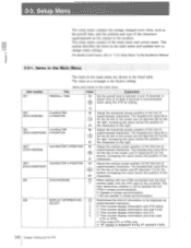
.... 15 002 (DVW-A500/500) CHARACTER H-POSITION 00 Adjust the horizontal screen position of the one of I superimposed characters. The hexadecimal value 00 is 56 for the bottom. This section describes the items in the Installation Manual. 3-3-1. Setup Menu" ...top of information to be displayed as SELECT 1 superimposed characters. 2 0: Time counter display information and VTR status. 3 1: Time counter display information and user's bits. 4 2: Time counter display information and CTL. 5 3: Time counter display information and time code (LTC or VITC). 4: Time code (LTC ...
.... 15 002 (DVW-A500/500) CHARACTER H-POSITION 00 Adjust the horizontal screen position of the one of I superimposed characters. The hexadecimal value 00 is 56 for the bottom. This section describes the items in the Installation Manual. 3-3-1. Setup Menu" ...top of information to be displayed as SELECT 1 superimposed characters. 2 0: Time counter display information and VTR status. 3 1: Time counter display information and user's bits. 4 2: Time counter display information and CTL. 5 3: Time counter display information and time code (LTC or VITC). 4: Time code (LTC ...

Operation Manual
Page 76
To record the user's bits, set the ID PRESET switch on the system set -up panel to ON. Recording Time Codes and User's Bits Recording an ID code as user's bits You can store an ID code in the Installation Manual. 4-12 Chapter 4 Recording For details of setting and storing an ID code, refer to OFF. Setup Menu" in non-volatile memory as user's bits data and subsequently recall it for recording. 4-2. To record the ID code, set the ID PRESET switch on the system set -up panel to "1-10.
To record the user's bits, set the ID PRESET switch on the system set -up panel to ON. Recording Time Codes and User's Bits Recording an ID code as user's bits You can store an ID code in the Installation Manual. 4-12 Chapter 4 Recording For details of setting and storing an ID code, refer to OFF. Setup Menu" in non-volatile memory as user's bits data and subsequently recall it for recording. 4-2. To record the ID code, set the ID PRESET switch on the system set -up panel to "1-10.

Operation Manual
Page 82
Preparing for Playback Displaying user's bits Supplying a playback time code to an external VTR without waveform distortion Using the following method allows time code signals, generated by the internal time ... to the setting of the TC selector on the sub control panel to PRESET. Outputting playback time codes as when displaying time codes, user's bits contained in the Installation Manual. 2 Set the TC GENERATOR REGEN/PRESET switch on the sub control panel to REGEN. 3 Set the TC GENERATOR INT/EXT switch on...
Preparing for Playback Displaying user's bits Supplying a playback time code to an external VTR without waveform distortion Using the following method allows time code signals, generated by the internal time ... to the setting of the TC selector on the sub control panel to PRESET. Outputting playback time codes as when displaying time codes, user's bits contained in the Installation Manual. 2 Set the TC GENERATOR REGEN/PRESET switch on the sub control panel to REGEN. 3 Set the TC GENERATOR INT/EXT switch on...
Operation Manual
Page 98
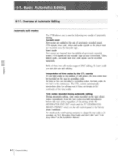
... counter To use the following two modes of previously recorded scenes. As long as the address of previously recorded scenes. Recording Time Codes and User's Bits" and "1-10. Assemble mode New scenes are inserted into the middle of edit points, the time codes must be continuous. Insert...on the player tape are breaks in the factory preset condition. CTL signals, time code, video and audio signals on the tape in the Installation Manual. 6-2 Chapter 6 Editing In insert mode you to be recorded separately. For details of the time codes. 6-1-1. Overview of these two edit modes...
... counter To use the following two modes of previously recorded scenes. As long as the address of previously recorded scenes. Recording Time Codes and User's Bits" and "1-10. Assemble mode New scenes are inserted into the middle of edit points, the time codes must be continuous. Insert...on the player tape are breaks in the factory preset condition. CTL signals, time code, video and audio signals on the tape in the Installation Manual. 6-2 Chapter 6 Editing In insert mode you to be recorded separately. For details of the time codes. 6-1-1. Overview of these two edit modes...

Operation Manual
Page 151
I A About this manual 5 AC IN connector 2-20, 2-21 Adjusting audio playback level 5-5 audio recording level 4-4 character display 3-12 Advanced editing 6-23 to 6-32 Advanced recording and playback functions 1-8 ..., 6-18 DF/NDF switch 2-17, 2-18 Digital betacam format 1-3 to 1-5 DISPLAY FULL/FINE button 2-3, 2-4 Displaying CTL codes 5-3 duration between two edit points 6-12 time codes 5-3 user's bits 5-4 DMC EDIT button 2-6 DOLBY NR switch 2-17, 2-18 Dynamic motion control (DMC) playback 5-14 to 5-18 Index I-1
I A About this manual 5 AC IN connector 2-20, 2-21 Adjusting audio playback level 5-5 audio recording level 4-4 character display 3-12 Advanced editing 6-23 to 6-32 Advanced recording and playback functions 1-8 ..., 6-18 DF/NDF switch 2-17, 2-18 Digital betacam format 1-3 to 1-5 DISPLAY FULL/FINE button 2-3, 2-4 Displaying CTL codes 5-3 duration between two edit points 6-12 time codes 5-3 user's bits 5-4 DMC EDIT button 2-6 DOLBY NR switch 2-17, 2-18 Dynamic motion control (DMC) playback 5-14 to 5-18 Index I-1
Operation Manual
Page 153
...14, 2-16 Search dial 2-10, 2-11 Selecting audio signals 4-3 audio signals to monitor 4-3 audio input signals 4-3 edit mode 6-5 meter scale mode of this manual 4 R REC button 2-8, 2-9 REC INHIBIT indicator 2-8, 2-9 REC INHIBIT switch 2-14, 2-15 REC level controls 2-3, 2-4 REC RUN/FREE RUN switch 2-17,... system 3-5 Reference signals for the input analog audio recording 4-5 real time 4-8 split edit points 6-8 to 6-10 switches 4-2, 5-2, 6-4 time codes 4-7, 4-8 user's bits 4-8 Setting up the VTR 3-1 to 3-19 Setup menu 3-8 to 3-11 SET UP SELECT switch 2-17, 2-19 SHUTTLE button 2-10, 2-11 SHUTTLE...
...14, 2-16 Search dial 2-10, 2-11 Selecting audio signals 4-3 audio signals to monitor 4-3 audio input signals 4-3 edit mode 6-5 meter scale mode of this manual 4 R REC button 2-8, 2-9 REC INHIBIT indicator 2-8, 2-9 REC INHIBIT switch 2-14, 2-15 REC level controls 2-3, 2-4 REC RUN/FREE RUN switch 2-17,... system 3-5 Reference signals for the input analog audio recording 4-5 real time 4-8 split edit points 6-8 to 6-10 switches 4-2, 5-2, 6-4 time codes 4-7, 4-8 user's bits 4-8 Setting up the VTR 3-1 to 3-19 Setup menu 3-8 to 3-11 SET UP SELECT switch 2-17, 2-19 SHUTTLE button 2-10, 2-11 SHUTTLE...
