Operation Manual
Page 2
...tested and found to comply with the limits for a digital device pursuant to take adequate measures. The shielded interface cable recommended in this manual must be connected to the terminal which is marked with the limits for a Class A digital device, pursuant to persons. To reduce... in Europe For the customers in the United Kingdom WARNING THIS APPARATUS MUST BE EARTHED IMPORTANT The wires in accordance with the instruction manual, may be required to comply with the letter N or coloured black. This equipment generates, uses, and can radiate radio frequency energy...
...tested and found to comply with the limits for a digital device pursuant to take adequate measures. The shielded interface cable recommended in this manual must be connected to the terminal which is marked with the limits for a Class A digital device, pursuant to persons. To reduce... in Europe For the customers in the United Kingdom WARNING THIS APPARATUS MUST BE EARTHED IMPORTANT The wires in accordance with the instruction manual, may be required to comply with the letter N or coloured black. This equipment generates, uses, and can radiate radio frequency energy...
Operation Manual
Page 3
... the Main Menu 3-8 3-3-2. Features 1-3 1-2-1. A Full Range of Contents 1 Connecting Digital Signals 3-2 3-1-2. Outline of Operation Suitable for Video Output and Servo System 3-4 3-2-1. Ease of the DVW-A500 series and DVW-500 series 1-2 1-2. Handling Cassettes 3-16 3-5-1. Lower Control Panel (Editing Section) 2-6 2-1-3. Recommended Cassettes 3-16 3-5-2. Optional Accessories 1-12 2-1. Connecting Reference Signals 3-6 3-3. Sub Control Panel...
... the Main Menu 3-8 3-3-2. Features 1-3 1-2-1. A Full Range of Contents 1 Connecting Digital Signals 3-2 3-1-2. Outline of Operation Suitable for Video Output and Servo System 3-4 3-2-1. Ease of the DVW-A500 series and DVW-500 series 1-2 1-2. Handling Cassettes 3-16 3-5-1. Lower Control Panel (Editing Section) 2-6 2-1-3. Recommended Cassettes 3-16 3-5-2. Optional Accessories 1-12 2-1. Connecting Reference Signals 3-6 3-3. Sub Control Panel...

Operation Manual
Page 4
... Mode 6-5 6-1-4. Cue Up and Preroll 6-13 6-1-7. Correcting Edit Points 6-17 6-1-9. Advanced Editing 6-23 6-2-1. Executing DMC Editing 6-23 6-2-2. Executing Quick Editing 6-27 6-2-3. Executing Preread Editing 6-31 6-3. Manual Editing 6-33 2 Table of Contents
... Mode 6-5 6-1-4. Cue Up and Preroll 6-13 6-1-7. Correcting Edit Points 6-17 6-1-9. Advanced Editing 6-23 6-2-1. Executing DMC Editing 6-23 6-2-2. Executing Quick Editing 6-27 6-2-3. Executing Preread Editing 6-31 6-3. Manual Editing 6-33 2 Table of Contents

Operation Manual
Page 7
...or have no previous experience with video equipment in broadcasting or production operators. This operation manual therefore assumes the operator already has a basic understanding of experience with this manual The DVW-A500/A500P/500/500P is essential reading to other chapters as necessary. Reading it first will ...chapters you have had limited experience with this type of the manual. Purpose and audience of Parts and Controls" and then refer to ensure that you are aware of the many features of the DVW-A500/A500P/500/ 500P digital videocassette recorder. If you read ...
...or have no previous experience with video equipment in broadcasting or production operators. This operation manual therefore assumes the operator already has a basic understanding of experience with this manual The DVW-A500/A500P/500/500P is essential reading to other chapters as necessary. Reading it first will ...chapters you have had limited experience with this type of the manual. Purpose and audience of Parts and Controls" and then refer to ensure that you are aware of the many features of the DVW-A500/A500P/500/ 500P digital videocassette recorder. If you read ...
Operation Manual
Page 8
...jog and shuttle playback, capstan override playback, and DMC playback. Chapter 6 Editing Explains basic and advanced automatic editing, as well as manual editing. Chapter 7 Maintenance Explains basic VTR maintenance. Appendixes ® Specifications Gives general specifications, and the principal specifications of that chapter...1 Overview Describes the principal features and functions of the chapters and appendix constituting this manual. Index 6 About This Manual Chapter 5 Playback Describes preparation for recording, time code settings, and basic recording operations. About This...
...jog and shuttle playback, capstan override playback, and DMC playback. Chapter 6 Editing Explains basic and advanced automatic editing, as well as manual editing. Chapter 7 Maintenance Explains basic VTR maintenance. Appendixes ® Specifications Gives general specifications, and the principal specifications of that chapter...1 Overview Describes the principal features and functions of the chapters and appendix constituting this manual. Index 6 About This Manual Chapter 5 Playback Describes preparation for recording, time code settings, and basic recording operations. About This...

Operation Manual
Page 9
...related information and cross references. t•D0I.BY" and the douhteD symbol 00 ore trademarks of operating procedure discription About This Manual 7 Cross references are also shown in illustrations. in the illustrations correspond to set edit points separately for Mau= O 6-6 Duo... information related to use or watch during operation are printed in italics. Conventions used in the steps described below . ON. VW-A500/AS00P only) C moire reduction tonne/ oxide tape. .rorgalaceunplayback. Carider,avlb„liigishalegj siplatck, ; 35-42-2Venable-Speed Playback odee...
...related information and cross references. t•D0I.BY" and the douhteD symbol 00 ore trademarks of operating procedure discription About This Manual 7 Cross references are also shown in illustrations. in the illustrations correspond to set edit points separately for Mau= O 6-6 Duo... information related to use or watch during operation are printed in italics. Conventions used in the steps described below . ON. VW-A500/AS00P only) C moire reduction tonne/ oxide tape. .rorgalaceunplayback. Carider,avlb„liigishalegj siplatck, ; 35-42-2Venable-Speed Playback odee...

Operation Manual
Page 10
... made, circuit diagrams, and so on request) Gives the additional information to fully maintain the VTR. About This Manual References In addition to this operation manual, the following manuals are available for the DVW-A500/A500P/500/500P. ® Installation Manual (supplied) Provides the information necessary to install the VTR and its peripherals. ® Maintenance...
... made, circuit diagrams, and so on request) Gives the additional information to fully maintain the VTR. About This Manual References In addition to this operation manual, the following manuals are available for the DVW-A500/A500P/500/500P. ® Installation Manual (supplied) Provides the information necessary to install the VTR and its peripherals. ® Maintenance...
Operation Manual
Page 16
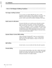
...for later use in shuttle mode, at a speed between -3 and + 3. Using this function, the previously read signals can connect two DVW-A500/500 series units to mixers for edit point access in either assemble or insert mode. Noiseless color pictures can also be monitored in variable mode... at a speed of editing functions You can be sent to enable automatic or manual editing in jog, shuttle, and variable modes. The VTR also features a full range of editing functions, including preview, review, preroll, and ...
...for later use in shuttle mode, at a speed between -3 and + 3. Using this function, the previously read signals can connect two DVW-A500/500 series units to mixers for edit point access in either assemble or insert mode. Noiseless color pictures can also be monitored in variable mode... at a speed of editing functions You can be sent to enable automatic or manual editing in jog, shuttle, and variable modes. The VTR also features a full range of editing functions, including preview, review, preroll, and ...

Operation Manual
Page 21
Easy-to-maintain plug-in boards The VTR uses plug-in circuit boards to perform self-diagnosis, after which it displays the relavant error code in an EIA-standard 19-inch rack. Chapter 1 Overview Mountable in standard 19-inch rack The unit can be mounted in the time counter display. Self-diagnosis When enabled with the maintenance menu, any malfunction causes the VTR to simplify servicing and inspection. For rack mounting, refer to the Installation Manual.
Easy-to-maintain plug-in boards The VTR uses plug-in circuit boards to perform self-diagnosis, after which it displays the relavant error code in an EIA-standard 19-inch rack. Chapter 1 Overview Mountable in standard 19-inch rack The unit can be mounted in the time counter display. Self-diagnosis When enabled with the maintenance menu, any malfunction causes the VTR to simplify servicing and inspection. For rack mounting, refer to the Installation Manual.
Operation Manual
Page 22
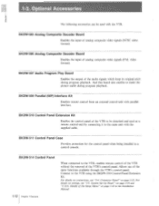
... which keep its original pitch during program playback. BKDW-511 Control Panel Case Provides protection for the control panel when being installed in the Installation Manual. Connector Panel" on connections, see "2-3.
... which keep its original pitch during program playback. BKDW-511 Control Panel Case Provides protection for the control panel when being installed in the Installation Manual. Connector Panel" on connections, see "2-3.
Operation Manual
Page 26
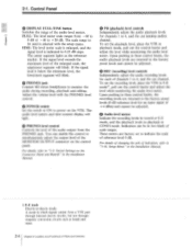
... recording level, place the VTR in these control knobs, the recording levels are returned to the factory preset levels and cannot be in the installation Manual. • PB (playback) level controls Independently adjust the audio playback levels for channels 1 to "1-10. O PHONES jack Connect 8O stereo headphones...levels in 0.25 dB steps. Adjust the volume level with the setup menu. To set the playback level, place the VTR in the Installation Manual. 1) E-E mode Electric-to be adjusted. Upon pushing in E-E mode, pull out the control knobs and adjust the level while monitoring the ...
... recording level, place the VTR in these control knobs, the recording levels are returned to the factory preset levels and cannot be in the installation Manual. • PB (playback) level controls Independently adjust the audio playback levels for channels 1 to "1-10. O PHONES jack Connect 8O stereo headphones...levels in 0.25 dB steps. Adjust the volume level with the setup menu. To set the playback level, place the VTR in the Installation Manual. 1) E-E mode Electric-to be adjusted. Upon pushing in E-E mode, pull out the control knobs and adjust the level while monitoring the ...
Operation Manual
Page 30
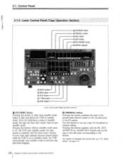
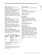
... point corresponding to the button. Pressing this button together with the IN, OUT, AUDIO IN or AUDIO OUT button cues up a tape for broadcast or manual editing. J PREROLL button Pressing this button in other than eight minutes (factory preset) elapse while the VTR is released, and the drum stops rotating. For...
... point corresponding to the button. Pressing this button together with the IN, OUT, AUDIO IN or AUDIO OUT button cues up a tape for broadcast or manual editing. J PREROLL button Pressing this button in other than eight minutes (factory preset) elapse while the VTR is released, and the drum stops rotating. For...
Operation Manual
Page 31
...E-E signals returns you to the video and audio monitored before you to monitor E-E signals. Holding down the REC button during recording or manual editing places the VTR in the VIDEO INPUT and REF mode respectively. G SERVO indicator Lights when the drum servo and capstan servo lock...of the cassette, as shown below. e) EDIT button Pressing this button together with the REC button or EDIT button starts recording or manual editing. Recording, editing and the selection of REC INHIBIT indicator REC INHIBIT switch Record inhibit REC INHIBIT plug indicator ON Pushed down/ ...
...E-E signals returns you to the video and audio monitored before you to monitor E-E signals. Holding down the REC button during recording or manual editing places the VTR in the VIDEO INPUT and REF mode respectively. G SERVO indicator Lights when the drum servo and capstan servo lock...of the cassette, as shown below. e) EDIT button Pressing this button together with the REC button or EDIT button starts recording or manual editing. Recording, editing and the selection of REC INHIBIT indicator REC INHIBIT switch Record inhibit REC INHIBIT plug indicator ON Pushed down/ ...
Operation Manual
Page 35
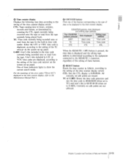
... the equipment connected to the REMOTE 1 connector, regardless of the setting of data to be displayed in the time counter display, refer to the Maintenance Manual Part I. One of Parts and Controls 2-13 e COUNTER buttons Press one of the buttons corresponding to the type of these indicators lights to show the...
... the equipment connected to the REMOTE 1 connector, regardless of the setting of data to be displayed in the time counter display, refer to the Maintenance Manual Part I. One of Parts and Controls 2-13 e COUNTER buttons Press one of the buttons corresponding to the type of these indicators lights to show the...

Operation Manual
Page 37
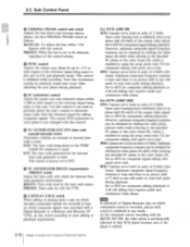
...momentary muting in case of emphasizing digital audio signals converted from the BVR-50/50P. Note that controls the digital video processor. MANUAL: To manually adjust the chrominance signal output level by using the SET UP control. Chapter 2 Location and Functions of Parts and Controls 2-15... REMOTE: The optional BVR-50/50P remote control unit controls the video processor. Set the Y/C delay switch as the reference signal for DVW-A500/...
...momentary muting in case of emphasizing digital audio signals converted from the BVR-50/50P. Note that controls the digital video processor. MANUAL: To manually adjust the chrominance signal output level by using the SET UP control. Chapter 2 Location and Functions of Parts and Controls 2-15... REMOTE: The optional BVR-50/50P remote control unit controls the video processor. Set the Y/C delay switch as the reference signal for DVW-A500/...
Operation Manual
Page 38
...editing or playing back a tape on which decoded component signals are recorded (a tape on which composite signals were recorded with the control. For DVW-A500/500 2FD: Capstan servo locks in units of 2 fields. Since color framing lock is inhibited, there is no phase shift (H-shift) of the...fields. As for component signal editing/playback. Sub Control Panel • CHROMA PHASE control and switch Adjusts the hue (burst and chroma relative phase). MANUAL: To adjust the hue within ± 200 ns with quick servo lock. 8FD: Capstan servo locks in units of Digital Betacam tape on playback ...
...editing or playing back a tape on which decoded component signals are recorded (a tape on which composite signals were recorded with the control. For DVW-A500/500 2FD: Capstan servo locks in units of 2 fields. Since color framing lock is inhibited, there is no phase shift (H-shift) of the...fields. As for component signal editing/playback. Sub Control Panel • CHROMA PHASE control and switch Adjusts the hue (burst and chroma relative phase). MANUAL: To adjust the hue within ± 200 ns with quick servo lock. 8FD: Capstan servo locks in units of Digital Betacam tape on playback ...
Operation Manual
Page 40
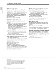
...format oxide tape. NDF: Non-drop-frame mode. O TC (time code) selector Determines whether the time code displayed in the Installation Manual. REC RUN: The time code advances only during recording. O VITC (Vertical Interval Time Code) switch Selects whether VITC signals are trademarks...Dolby NR Dolby noise reduction manufactured under license from Dolby Laboratories Licensing Corporation. O DOLBY NR switch (for DVW-A500/500 only) Selects whether the time code generator and CTL, counter advance in the Installation Manual. "DOLBY" and the double-D symbol DO are recorded.
...format oxide tape. NDF: Non-drop-frame mode. O TC (time code) selector Determines whether the time code displayed in the Installation Manual. REC RUN: The time code advances only during recording. O VITC (Vertical Interval Time Code) switch Selects whether VITC signals are trademarks...Dolby NR Dolby noise reduction manufactured under license from Dolby Laboratories Licensing Corporation. O DOLBY NR switch (for DVW-A500/500 only) Selects whether the time code generator and CTL, counter advance in the Installation Manual. "DOLBY" and the double-D symbol DO are recorded.

Operation Manual
Page 41
... O through the CONTROL PANEL connector, controls this VTR. cv; The VTR will be set up menu settings for the selected memory bank in the Installation Manual. ON: Superimposed.
... O through the CONTROL PANEL connector, controls this VTR. cv; The VTR will be set up menu settings for the selected memory bank in the Installation Manual. ON: Superimposed.
Operation Manual
Page 44
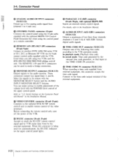
..., refer to the time code output terminal of the volume level with optional BIWW-509) Inputs an external remote control signal. Connect to the Installation Manual. © AUDIO OUTPUT (AES/EBU) connectors (XLR-3-32) Output a maximum of two lines (four channels: channels 1/2 and 3/4) of Parts and ...Controls The REMOTE 1-IN and OUT connectors can make a bridge connection. • MONITOR OUTPUT connectors (XLR-3-32) Output signals to another DVW-A500/500 series VTR or D-1, D-2, or Betacam SP VTR via the 9-pin remote control cable supplied with the MONITOR SELECT button and the AUDIO INPUT...
..., refer to the time code output terminal of the volume level with optional BIWW-509) Inputs an external remote control signal. Connect to the Installation Manual. © AUDIO OUTPUT (AES/EBU) connectors (XLR-3-32) Output a maximum of two lines (four channels: channels 1/2 and 3/4) of Parts and ...Controls The REMOTE 1-IN and OUT connectors can make a bridge connection. • MONITOR OUTPUT connectors (XLR-3-32) Output signals to another DVW-A500/500 series VTR or D-1, D-2, or Betacam SP VTR via the 9-pin remote control cable supplied with the MONITOR SELECT button and the AUDIO INPUT...
Operation Manual
Page 52
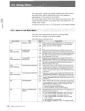
... displayed as the preroll time, and the position and type of the screen and 24 (decimal 36) for the bottom. The value in the Installation Manual. 3-3-1. A preroll time of the screen and 6F (decimal 111) for the far right. This section describes the items in the main menu Title Value ...the far right. The hexadecimal value 00 is 14 for the far left of the screen and 22 (decimal 34) for editing. 15 002 (DVW-A500/500) CHARACTER H-POSITION 00 Adjust the horizontal screen position of the one of I superimposed characters. Increasing the value lowers the position of the 6F ...
... displayed as the preroll time, and the position and type of the screen and 24 (decimal 36) for the bottom. The value in the Installation Manual. 3-3-1. A preroll time of the screen and 6F (decimal 111) for the far right. This section describes the items in the main menu Title Value ...the far right. The hexadecimal value 00 is 14 for the far left of the screen and 22 (decimal 34) for editing. 15 002 (DVW-A500/500) CHARACTER H-POSITION 00 Adjust the horizontal screen position of the one of I superimposed characters. Increasing the value lowers the position of the 6F ...
