Operation Manual
Page 20
... number of Operation Suitable for Editing Setup menus The initial settings for use as necessary. Remote control operation The VTR has RS-422A serial 9-pin and optional parallel 50-pin remote connectors. It can be angled as a remote control unit, by combining it with the BKDW-510/511 Control Panel Extension Kit/Control...
... number of Operation Suitable for Editing Setup menus The initial settings for use as necessary. Remote control operation The VTR has RS-422A serial 9-pin and optional parallel 50-pin remote connectors. It can be angled as a remote control unit, by combining it with the BKDW-510/511 Control Panel Extension Kit/Control...
Operation Manual
Page 22
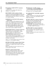
... original pitch during program playback. Connector Panel" on page 1-42 in a control console. And this board also enables to the VTR, enables remote control of the VTR without the removal of the VTR's control panel. For details on connections, see "2-3. BKDW-509 Parallel (50P) Interface Kit ...Analog Composite Decoder Board Enables the input of analog composite video signals (NTSC video format). Details of the VTR to be used as a remote control unit by connecting it to the main unit with the supplied cable. Connect to the VTR using the BKDW-510 Control Panel Extension Kit...
... original pitch during program playback. Connector Panel" on page 1-42 in a control console. And this board also enables to the VTR, enables remote control of the VTR without the removal of the VTR's control panel. For details on connections, see "2-3. BKDW-509 Parallel (50P) Interface Kit ...Analog Composite Decoder Board Enables the input of analog composite video signals (NTSC video format). Details of the VTR to be used as a remote control unit by connecting it to the main unit with the supplied cable. Connect to the VTR using the BKDW-510 Control Panel Extension Kit...
Operation Manual
Page 25
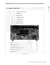
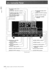
2 1 1. Upper Control Panel o DISPLAY FULL/FINE button O PHONES jack O POWER switch 0 PHONES level control PB level controls O REC level controls Audio level meters !Lf Jo • .nrao ear nue,or II II II I II .1010 ow • INT U SWIM MEM , II II O Indicators 0 MONITOR SELECT button a) INPUT SELECT button (j) AUDIO INPUT/MONITOR SELECT buttons ® VIDEO INPUT SELECT buttons REMOTE buttons Upper control panel 901E9SE Chapter 2 Location and Functions of Parts and Controls 2-3
2 1 1. Upper Control Panel o DISPLAY FULL/FINE button O PHONES jack O POWER switch 0 PHONES level control PB level controls O REC level controls Audio level meters !Lf Jo • .nrao ear nue,or II II II I II .1010 ow • INT U SWIM MEM , II II O Indicators 0 MONITOR SELECT button a) INPUT SELECT button (j) AUDIO INPUT/MONITOR SELECT buttons ® VIDEO INPUT SELECT buttons REMOTE buttons Upper control panel 901E9SE Chapter 2 Location and Functions of Parts and Controls 2-3
Operation Manual
Page 27
... locked to ON. • MONITOR SELECT button Selects the signals output from the external equipment (1 or 2), all of the system set to the REMOTE 14N (9P)/OUT (9P) connectors control the VTR. You can mix the signals to be monitored by the SET UP SELECT switch of the tape...4) for the STOP and EJECT buttons. SW: The serial digital video signal being input to the COMPOSITE VIDEO INPUT connector is selected. ® REMOTE buttons Determine the device used to the SERIAL V/A INPUT connector is restorable. COMPOSITE: The analog composite video signal being input to control the VTR.
... locked to ON. • MONITOR SELECT button Selects the signals output from the external equipment (1 or 2), all of the system set to the REMOTE 14N (9P)/OUT (9P) connectors control the VTR. You can mix the signals to be monitored by the SET UP SELECT switch of the tape...4) for the STOP and EJECT buttons. SW: The serial digital video signal being input to the COMPOSITE VIDEO INPUT connector is selected. ® REMOTE buttons Determine the device used to the SERIAL V/A INPUT connector is restorable. COMPOSITE: The analog composite video signal being input to control the VTR.
Operation Manual
Page 29
... buttons after setting an audio edit point, the corresponding time data will be controlled by simultaneously playing back them with the ENTRY button to the REMOTE 1-IN (9P)/OUT (9P) connectors. e ENTRY button Sets an edit point. If an IN point is set when you press one of the edit on...
... buttons after setting an audio edit point, the corresponding time data will be controlled by simultaneously playing back them with the ENTRY button to the REMOTE 1-IN (9P)/OUT (9P) connectors. e ENTRY button Sets an edit point. If an IN point is set when you press one of the edit on...
Operation Manual
Page 35
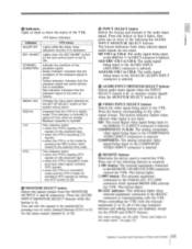
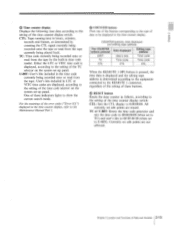
...address The COUNTER buttons pressed Data displayed Editing tape address U-BIT User's bits Time code TC Time code Time code CTL CTL CTL When the REMOTE 1 (9P) button is pressed, the time data is displayed and the editing tape address is displayed, according to the setting of these ...indicators lights to show the current search mode. Either the LTC or VITC time code is determined according to the equipment connected to the REMOTE 1 connector, regardless of the setting of the TC selector on the system set -up panel. e COUNTER buttons Press one of the buttons...
...address The COUNTER buttons pressed Data displayed Editing tape address U-BIT User's bits Time code TC Time code Time code CTL CTL CTL When the REMOTE 1 (9P) button is pressed, the time data is displayed and the editing tape address is displayed, according to the setting of these ...indicators lights to show the current search mode. Either the LTC or VITC time code is determined according to the equipment connected to the REMOTE 1 connector, regardless of the setting of the TC selector on the system set -up panel. e COUNTER buttons Press one of the buttons...

Operation Manual
Page 37
...as the reference signal for playback and digital audio recording. PRESET: When the Y/C delay is not to be used as the reference signal for DVW-A500/A500P only) Adjusts the Y/C delay of the video signal. REF: Selects the external reference signal to be adjusted. INPUT VIDEO: Selects the input .... Switching this switch to ON turns on the KEY INHIBIT indicator of the upper control panel and inhibits all or some key inputs of the REMOTE, VIDEO INPUT SELECT, AUDIO INPUT/MONITOR SELECT buttons, and the buttons in the editing section. Setup Menu" in the Installation Manual. PRESET: To ...
...as the reference signal for playback and digital audio recording. PRESET: When the Y/C delay is not to be used as the reference signal for DVW-A500/A500P only) Adjusts the Y/C delay of the video signal. REF: Selects the external reference signal to be adjusted. INPUT VIDEO: Selects the input .... Switching this switch to ON turns on the KEY INHIBIT indicator of the upper control panel and inhibits all or some key inputs of the REMOTE, VIDEO INPUT SELECT, AUDIO INPUT/MONITOR SELECT buttons, and the buttons in the editing section. Setup Menu" in the Installation Manual. PRESET: To ...
Operation Manual
Page 42
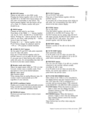
..." CUM.,/ ® VIDEO CONTROL connector RS232C connector (D PARALLEL I - AUDIO INPUT LEVEL/600D termination switch ANALOG AUDIO INPUT connectors e ANALOG AUDIO OUTPUT connectors CONTROL PANEL connector REMOTE 1-IN/OUT (9P) connectors MONITOR OUTPUT connectors Connector panel ',Rat LE. 2-4 C 0 COMPOSITE VIDEO OUTPUT connectors 0 COMPONENT VIDEO INPUT connectors O COMPOSITE VIDEO INPUT connectors and 75O...
..." CUM.,/ ® VIDEO CONTROL connector RS232C connector (D PARALLEL I - AUDIO INPUT LEVEL/600D termination switch ANALOG AUDIO INPUT connectors e ANALOG AUDIO OUTPUT connectors CONTROL PANEL connector REMOTE 1-IN/OUT (9P) connectors MONITOR OUTPUT connectors Connector panel ',Rat LE. 2-4 C 0 COMPOSITE VIDEO OUTPUT connectors 0 COMPONENT VIDEO INPUT connectors O COMPOSITE VIDEO INPUT connectors and 75O...
Operation Manual
Page 44
... equipment, this connector is being used to make setting to the VTR operation mode. Used when you edit using the control panel as a remote controller. • REMOTE 1-IN (9P)/OUT (9P) connectors (D-sub 9-pin) Connect to be used for communication, the RS-232C indicator on the Connector Panel and... VTRs and the BVE-900/910/2000/9000/9100 editing control unit. Select the signals to another DVW-A500/500 series VTR or D-1, D-2, or Betacam SP VTR via the 9-pin remote control cable supplied with the MONITOR SELECT button and the AUDIO INPUT/MONITOR SELECT buttons. In playback mode:...
... equipment, this connector is being used to make setting to the VTR operation mode. Used when you edit using the control panel as a remote controller. • REMOTE 1-IN (9P)/OUT (9P) connectors (D-sub 9-pin) Connect to be used for communication, the RS-232C indicator on the Connector Panel and... VTRs and the BVE-900/910/2000/9000/9100 editing control unit. Select the signals to another DVW-A500/500 series VTR or D-1, D-2, or Betacam SP VTR via the 9-pin remote control cable supplied with the MONITOR SELECT button and the AUDIO INPUT/MONITOR SELECT buttons. In playback mode:...
Operation Manual
Page 46
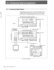
... OO OO DVR-2100 (recorder) Connecting Digital Signals 3-2 Chapter 3 Setting Up the VTR in remote cabl Input COMPONENT or COMPOSITE VIDEO OUTPUT a 0 0 O O O z z'a z'a Video monitor DVW-A500 series and DVW-500 series (player) OOO Q (0 O O-O ou 6° O 0 ...O OO 664 04 t2, io 0O0 O REMOTE 1-IN (9P) 01 0 0O0 SERIAL V/A OUTPUT co O z SERIAL V/A INPUT DVW-A500/A500P/500/500P O,O CO 0 --•0 o • o 666460.00__ SERIAL V/A OUTPUT 0O0 REMOTE 1-IN (9P) T 1 0 0O0 REMOTE 1-OUT (9P) w O z 03 9-pin remote cable Output REMOTE-1 SERIAL V/A IN - -- -- -- ' ° ...
... OO OO DVR-2100 (recorder) Connecting Digital Signals 3-2 Chapter 3 Setting Up the VTR in remote cabl Input COMPONENT or COMPOSITE VIDEO OUTPUT a 0 0 O O O z z'a z'a Video monitor DVW-A500 series and DVW-500 series (player) OOO Q (0 O O-O ou 6° O 0 ...O OO 664 04 t2, io 0O0 O REMOTE 1-IN (9P) 01 0 0O0 SERIAL V/A OUTPUT co O z SERIAL V/A INPUT DVW-A500/A500P/500/500P O,O CO 0 --•0 o • o 666460.00__ SERIAL V/A OUTPUT 0O0 REMOTE 1-IN (9P) T 1 0 0O0 REMOTE 1-OUT (9P) w O z 03 9-pin remote cable Output REMOTE-1 SERIAL V/A IN - -- -- -- ' ° ...
Operation Manual
Page 47
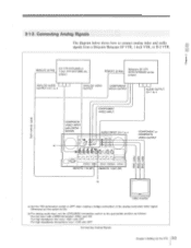
... DVR-28/20 or 1-inch VTR BVH-3000 etc. (player) REMOTE (9 PIN) Betacam SP VTR BVW-75/70/65/60 series (player) ANALOG AUDIO OUTPUT CH-1 to... termination switch to ON. 3-1-2. b) For analog audio input, set the switch to OFF when making a bridge connection of Jo~ lo=oj REMOTE 1-OUT (9P) a) a) a) as follows: For line input with a 600O termination: HIGH with ON For high-impedance line input: HIGH...or D-2 VTR. Connecting Analog Signals The diagram below shows how to 4 _ - 1 COMPONENT or COMPOSITE VIDEO OUTPUT J 0• 3 0 REMOTE 1-IN (9P) 00 o of the analog composite video signal.
... DVR-28/20 or 1-inch VTR BVH-3000 etc. (player) REMOTE (9 PIN) Betacam SP VTR BVW-75/70/65/60 series (player) ANALOG AUDIO OUTPUT CH-1 to... termination switch to ON. 3-1-2. b) For analog audio input, set the switch to OFF when making a bridge connection of Jo~ lo=oj REMOTE 1-OUT (9P) a) a) a) as follows: For line input with a 600O termination: HIGH with ON For high-impedance line input: HIGH...or D-2 VTR. Connecting Analog Signals The diagram below shows how to 4 _ - 1 COMPONENT or COMPOSITE VIDEO OUTPUT J 0• 3 0 REMOTE 1-IN (9P) 00 o of the analog composite video signal.
Operation Manual
Page 52
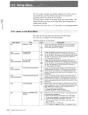
...to the monitor. Increasing the value lowers the position of the 6F characters. 004 SYNCHRONIZE 0 When editing with two VTRs connected over the 9-pin 1 remote cable, with the VTR used as the preroll time, and the position and type of at least 5 seconds is displayed during DT playback mode. ...For details of the main menu and system menu. Increasing the value moves the position of 22 the characters to the right. 003') (DVW-A500/500) CHARACTER V-POSITION 00 Adjust the vertical screen position of the first line of I superimposed characters. The value in the main menu Title ...
...to the monitor. Increasing the value lowers the position of the 6F characters. 004 SYNCHRONIZE 0 When editing with two VTRs connected over the 9-pin 1 remote cable, with the VTR used as the preroll time, and the position and type of at least 5 seconds is displayed during DT playback mode. ...For details of the main menu and system menu. Increasing the value moves the position of 22 the characters to the right. 003') (DVW-A500/500) CHARACTER V-POSITION 00 Adjust the vertical screen position of the first line of I superimposed characters. The value in the main menu Title ...
Operation Manual
Page 66
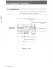
... 4 Recording Setting Switches Prior to recording, set to record REC level controls: Recording levels (page 4-4) op DD 0 o rOH 1Ocaol go] 0 1O, = o :DOD D LI LI OOOLIA D O O - REMOTE buttons: None of REMOTE buttons is lit.
... 4 Recording Setting Switches Prior to recording, set to record REC level controls: Recording levels (page 4-4) op DD 0 o rOH 1Ocaol go] 0 1O, = o :DOD D LI LI OOOLIA D O O - REMOTE buttons: None of REMOTE buttons is lit.
Operation Manual
Page 80
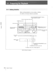
... switch: ON Control panel PB level controls: --Playback level C f.') • DJ 00 tclIDOqb HD[IOU [D OLi 6: aDr aD O 00 OOOOLi 00000 ra DOD E3 REMOTE buttons: None of REMOTE buttons is lit. -COUNTER buttons: Time data to display (page 5-3) Switch settings for playback 5-2 Chapter 5 Playback Sub control , panel .0 ! 07,---loaoaoao-Eloaoc) System...
... switch: ON Control panel PB level controls: --Playback level C f.') • DJ 00 tclIDOqb HD[IOU [D OLi 6: aDr aD O 00 OOOOLi 00000 ra DOD E3 REMOTE buttons: None of REMOTE buttons is lit. -COUNTER buttons: Time data to display (page 5-3) Switch settings for playback 5-2 Chapter 5 Playback Sub control , panel .0 ! 07,---loaoaoao-Eloaoc) System...
Operation Manual
Page 100
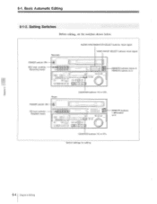
...: TC or CTL POWER switch: ON PB level controls: Playback levels 06 DO ❑IL DuDD o goo o ,r1 , u ooOo On o u 0000 1 000001 O DO, p fi DDD O O REMOTE buttons: 1 (9P) button is lit COUNTER buttons: TC or CTL Switch settings for editing 6-4 Chapter 6 Editing Setting Switches Before editing, set the switches shown below...
...: TC or CTL POWER switch: ON PB level controls: Playback levels 06 DO ❑IL DuDD o goo o ,r1 , u ooOo On o u 0000 1 000001 O DO, p fi DDD O O REMOTE buttons: 1 (9P) button is lit COUNTER buttons: TC or CTL Switch settings for editing 6-4 Chapter 6 Editing Setting Switches Before editing, set the switches shown below...
Operation Manual
Page 146
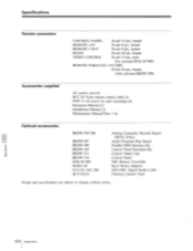
...sub 25-pin, female VIDEO CONTROL D-sub 15-pin, male (for optional BVR-50/50P) REMOTE PARALLEL I/O (50P) D-sub 50-pin, female (with optional BKDW-509) Accessories supplied AC power cord (1) RCC-5G 9-pin remote control cable (1) PSW 4 x 16 screws for rack mounting (4) Operation Manual (1) Installation Manual... Audio Program Play Board Parallel (50P) Interface Kit Control Panel Extension Kit Control Panel Case Control Panel 'TBC Remote Controller Rack Mount Adaptor AES/EBU Digital Audio Cable Cleaning Cassette Tape Design and specifications are subject to change without notice. A-8 ...
...sub 25-pin, female VIDEO CONTROL D-sub 15-pin, male (for optional BVR-50/50P) REMOTE PARALLEL I/O (50P) D-sub 50-pin, female (with optional BKDW-509) Accessories supplied AC power cord (1) RCC-5G 9-pin remote control cable (1) PSW 4 x 16 screws for rack mounting (4) Operation Manual (1) Installation Manual... Audio Program Play Board Parallel (50P) Interface Kit Control Panel Extension Kit Control Panel Case Control Panel 'TBC Remote Controller Rack Mount Adaptor AES/EBU Digital Audio Cable Cleaning Cassette Tape Design and specifications are subject to change without notice. A-8 ...
Operation Manual
Page 153
... playback speeds 6-24, 6-25 for video output and servo system 3-4 to 2-5 Using noise reduction 5-7 Index 1-3 VIDEO INPUT connectors and 75O termination switch 2-20, 2-21 REMOTE buttons 2-3, 2-5 REMOTE 1-IN/OUT connectors 2-20, 2-22 Removing the cassette when the tape is slack 7-2 RESET button 2-12, 2-13 Restoring the factory preset values 3-11 REVIEW button...
... playback speeds 6-24, 6-25 for video output and servo system 3-4 to 2-5 Using noise reduction 5-7 Index 1-3 VIDEO INPUT connectors and 75O termination switch 2-20, 2-21 REMOTE buttons 2-3, 2-5 REMOTE 1-IN/OUT connectors 2-20, 2-22 Removing the cassette when the tape is slack 7-2 RESET button 2-12, 2-13 Restoring the factory preset values 3-11 REVIEW button...
Installation Manual
Page 8
... maintenance and servicing information necessary for the principal block and board replacement. • Maintenance Manual Part 2 (available on request) PROTOCOL OF REMOTE-1 (9Pin) CONNECTOR This Manual describes the protocol information necessary for general parts replacement and includes alignments, schematic diagrams, board layouts, detailed parts... Manual (available on request) These manuals describes detailed information necessary for controlling the VTR via RS-422A (9-pin serial remote). 4 BKDW-515 Please contact the Sony service organization to install the VTR and its peripherals.
... maintenance and servicing information necessary for the principal block and board replacement. • Maintenance Manual Part 2 (available on request) PROTOCOL OF REMOTE-1 (9Pin) CONNECTOR This Manual describes the protocol information necessary for general parts replacement and includes alignments, schematic diagrams, board layouts, detailed parts... Manual (available on request) These manuals describes detailed information necessary for controlling the VTR via RS-422A (9-pin serial remote). 4 BKDW-515 Please contact the Sony service organization to install the VTR and its peripherals.
Installation Manual
Page 20
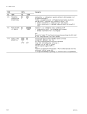
... is executed even though the REC inhibit tab of the DVW. Except 0000: Returns the values numeric as it is prepared exclusively for the 9 pin remote command DEVICE TYPE REQUEST (00h, 11h). 0000: Returns the original device type data of an analog tape used is not guaranteed. 3-2 BKDW-515 This item...
... is executed even though the REC inhibit tab of the DVW. Except 0000: Returns the values numeric as it is prepared exclusively for the 9 pin remote command DEVICE TYPE REQUEST (00h, 11h). 0000: Returns the original device type data of an analog tape used is not guaranteed. 3-2 BKDW-515 This item...
Installation Manual
Page 21
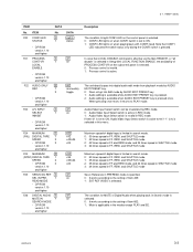
...-802. 1: Mute is applicable in PREREAD mode is specified. 0: It works according to PLAY mode. Note that LOCAL DISABLE command is effective via the 9pin REMOTE, or "all disable" is limited in search mode. 0: 50 times speed in FF, REW, and SHUTTLE mode 1: 35 times speed in FF, REW, and SHUTTLE...
...-802. 1: Mute is applicable in PREREAD mode is specified. 0: It works according to PLAY mode. Note that LOCAL DISABLE command is effective via the 9pin REMOTE, or "all disable" is limited in search mode. 0: 50 times speed in FF, REW, and SHUTTLE mode 1: 35 times speed in FF, REW, and SHUTTLE...


