Operation Manual
Page 3
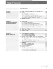
...... 2-10 2-1-5. Connector Panel 2-20 34. Connecting Analog Signals 3-3 3-2. Reference Signal for the Internal Reference Video Signal Generator 3-4 3-2-2. Recommended Cassettes 3-16 3-5-2. Chapter 1 Overview Chapter 2 Location and Functions of Operation Suitable...Contents 1 Connecting External Equipment 3-2 3-1-1. Connecting Digital Signals 3-2 3-1-2. Preventing Accidental Erasure 3-19 Table of the DVW-A500 series and DVW-500 series 1-2 1-2. Features 1-3 1-2-1. Optional Accessories 1-12 2-1. Superimposed Characters 3-12 3-5. Control Panel...
...... 2-10 2-1-5. Connector Panel 2-20 34. Connecting Analog Signals 3-3 3-2. Reference Signal for the Internal Reference Video Signal Generator 3-4 3-2-2. Recommended Cassettes 3-16 3-5-2. Chapter 1 Overview Chapter 2 Location and Functions of Operation Suitable...Contents 1 Connecting External Equipment 3-2 3-1-1. Connecting Digital Signals 3-2 3-1-2. Preventing Accidental Erasure 3-19 Table of the DVW-A500 series and DVW-500 series 1-2 1-2. Features 1-3 1-2-1. Optional Accessories 1-12 2-1. Superimposed Characters 3-12 3-5. Control Panel...

Operation Manual
Page 4
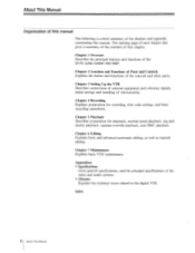
... be Displayed 5-3 5-1-3. Playback 5-6 5-2-1. Overview of Contents Executing Preread Editing 6-31 6-3. Table of Contents Chapter 4 Recording Chapter 5 Playback Chapter 6 Editing 44. Setting Switches 4-2 4-1-2. Monitoring Simultaneous Playback Video and Audio As They Are Recorded 4-5 4-1-5. Preparing for Recording 4-2 4-1-1. Recording External Time Codes without Change.... 4-11 4-3. Recording Time Codes and User's Bits 4-6 4-2-1. Executing Quick Editing...
... be Displayed 5-3 5-1-3. Playback 5-6 5-2-1. Overview of Contents Executing Preread Editing 6-31 6-3. Table of Contents Chapter 4 Recording Chapter 5 Playback Chapter 6 Editing 44. Setting Switches 4-2 4-1-2. Monitoring Simultaneous Playback Video and Audio As They Are Recorded 4-5 4-1-5. Preparing for Recording 4-2 4-1-1. Recording External Time Codes without Change.... 4-11 4-3. Recording Time Codes and User's Bits 4-6 4-2-1. Executing Quick Editing...

Operation Manual
Page 7
... the entire manual. 5 About This Manual If you are aware of the many features of VTR and broadcasting technology, and experience with video equipment in broadcasting or production operators. This manual is intended for use by professionals working in general, we recommend that you decide which ...that you read most carefully, depending on your degree of experience, however, Chapter 1 "Overview" is designed for users of the DVW-A500/A500P/500/ 500P digital videocassette recorder. This operation manual therefore assumes the operator already has a basic understanding of the DVW...
... the entire manual. 5 About This Manual If you are aware of the many features of VTR and broadcasting technology, and experience with video equipment in broadcasting or production operators. This manual is intended for use by professionals working in general, we recommend that you decide which ...that you read most carefully, depending on your degree of experience, however, Chapter 1 "Overview" is designed for users of the DVW-A500/A500P/500/ 500P digital videocassette recorder. This operation manual therefore assumes the operator already has a basic understanding of the DVW...
Operation Manual
Page 8
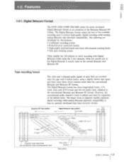
Chapter 3 Setting Up the VTR Describes connections of external equipment and reference signals, initial settings and handling of the video and audio systems. Glossary Explains the technical terms related to the digital VTR. Chapter 6 Editing Explains basic and advanced automatic editing, as well... and functions of that chapter. Index 6 About This Manual The opening page of each chapter also gives a summary of the contents of the DVW-A500/A500P/500/500P. About This Manual Organization of this manual The following is a brief summary of the controls and other parts. Chapter 2 Location and...
Chapter 3 Setting Up the VTR Describes connections of external equipment and reference signals, initial settings and handling of the video and audio systems. Glossary Explains the technical terms related to the digital VTR. Chapter 6 Editing Explains basic and advanced automatic editing, as well... and functions of that chapter. Index 6 About This Manual The opening page of each chapter also gives a summary of the contents of the DVW-A500/A500P/500/500P. About This Manual Organization of this manual The following is a brief summary of the controls and other parts. Chapter 2 Location and...

Operation Manual
Page 9
... are also shown in italics. Basic Rotnntatic Editing Setting Eat )rote Thw desctibes how to set edit porn's (IN tont OUT points). VW-A500/AS00P only) C moire reduction tonne/ oxide tape. .rorgalaceunplayback. In insert mode, a technique called split editing allows you may have to present... 35-42-2Venable-Speed Playback odee" on 3 Press the ENTRY button together with the IN (or OUT) button. Manual. Isabled for video and audio. Controls and switches used This manual uses the following formats to describe the operating procedures and to use or watch during operation ...
... are also shown in italics. Basic Rotnntatic Editing Setting Eat )rote Thw desctibes how to set edit porn's (IN tont OUT points). VW-A500/AS00P only) C moire reduction tonne/ oxide tape. .rorgalaceunplayback. In insert mode, a technique called split editing allows you may have to present... 35-42-2Venable-Speed Playback odee" on 3 Press the ENTRY button together with the IN (or OUT) button. Manual. Isabled for video and audio. Controls and switches used This manual uses the following formats to describe the operating procedures and to use or watch during operation ...
Operation Manual
Page 13
...record/playback head Digital Betacam tape pattern Cue audio s, , Video Audio CH-1 to 4 Video , Time code , Control Tape pattern Full CTL erase head head a i I e a ; r -l- Tape recording format The video and 4-channel audio signals of each field are developed for expansion...specially developed time base corrector circuits. r 4_____i _ a a Ia a a® Chapter 1 Overview 1-3 2 Features 1-2-1. Digital Betacam Format The DVW-A500/A500P/500/500P adopt the newly developed Digital Betacam format as a a a i a ; However, the conventional audio channel-1 track is deleted and ...
...record/playback head Digital Betacam tape pattern Cue audio s, , Video Audio CH-1 to 4 Video , Time code , Control Tape pattern Full CTL erase head head a i I e a ; r -l- Tape recording format The video and 4-channel audio signals of each field are developed for expansion...specially developed time base corrector circuits. r 4_____i _ a a Ia a a® Chapter 1 Overview 1-3 2 Features 1-2-1. Digital Betacam Format The DVW-A500/A500P/500/500P adopt the newly developed Digital Betacam format as a a a i a ; However, the conventional audio channel-1 track is deleted and ...

Operation Manual
Page 15
...adopts Scrambled NRZI channel coding system that is added to the SMPTE 259M/EBU T.3267/CCIR 656-III standards, handles component video signal and 4-channel digital audio signals with the ECC added are compensated by newly developed coefficient recording system, whose key ...field shuffling, blocking, discrete cosine transform (DCT), quantizing, and variable length coding. Chapter 1 Overview 1-5 Bit rate reduction encoder The video data are encoded into composite digital, then D/A converted into CCIR 601 standard parallel data. Digital audio signals are converted into serial data ...
...adopts Scrambled NRZI channel coding system that is added to the SMPTE 259M/EBU T.3267/CCIR 656-III standards, handles component video signal and 4-channel digital audio signals with the ECC added are compensated by newly developed coefficient recording system, whose key ...field shuffling, blocking, discrete cosine transform (DCT), quantizing, and variable length coding. Chapter 1 Overview 1-5 Bit rate reduction encoder The video data are encoded into composite digital, then D/A converted into CCIR 601 standard parallel data. Digital audio signals are converted into serial data ...
Operation Manual
Page 16
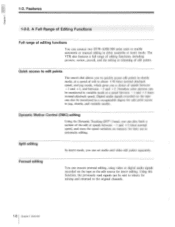
...head, you a choice of still to about ± 50 times normal playback speed, and jog mode, which gives you can set audio and video edit points separately. Noiseless color pictures can be monitored in a recognizable degree for insert editing. Features mow_ 1-2-2. 1-2. The VTR also features a...enable automatic or manual editing in jog, shuttle, and variable modes. Using this function, the previously read signals can connect two DVW-A500/500 series units to the original channels. 1-6 Chapter 1 Overview A Full Range of Editing Functions Full range of edit points. ...
...head, you a choice of still to about ± 50 times normal playback speed, and jog mode, which gives you can set audio and video edit points separately. Noiseless color pictures can be monitored in a recognizable degree for insert editing. Features mow_ 1-2-2. 1-2. The VTR also features a...enable automatic or manual editing in jog, shuttle, and variable modes. Using this function, the previously read signals can connect two DVW-A500/500 series units to the original channels. 1-6 Chapter 1 Overview A Full Range of Editing Functions Full range of edit points. ...

Operation Manual
Page 17
... Edit duration display Digital time counter You can display the duration between any two of edit points. 1) LTC (Longitudinal Time Code): Time code recorded on a video track during the vertical blanking interval.
... Edit duration display Digital time counter You can display the duration between any two of edit points. 1) LTC (Longitudinal Time Code): Time code recorded on a video track during the vertical blanking interval.
Operation Manual
Page 18
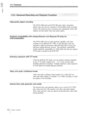
... digital recording The DVW-A500 series and DVW-500 series adopt component digital video and the four channels of 20-bit digital audio recording system with video and audio signals. Noiseless playback is also supported by the internal time code reader during playback. 1.8 Chapter 1 Overview Video and audio confidence heads Video and audio confidence heads...
... digital recording The DVW-A500 series and DVW-500 series adopt component digital video and the four channels of 20-bit digital audio recording system with video and audio signals. Noiseless playback is also supported by the internal time code reader during playback. 1.8 Chapter 1 Overview Video and audio confidence heads Video and audio confidence heads...
Operation Manual
Page 22
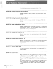
...to the VTR using the BKDW-510 Control Panel Extension Kit. BKDW-505 Analog Composite Decoder Board Enables the input of analog composite video signals (PAL video format). Connector Panel" on page 2-19 and "1-10-4. System Set-Up Panel" on page 2-22. BKDW-506 Analog Composite ...Decoder Board Enables the input of analog composite video signals (NTSC video format). Connect to make the picture stable during program playback. For details on page 1-42 in a control console. Details of the VTR...
...to the VTR using the BKDW-510 Control Panel Extension Kit. BKDW-505 Analog Composite Decoder Board Enables the input of analog composite video signals (PAL video format). Connector Panel" on page 2-19 and "1-10-4. System Set-Up Panel" on page 2-22. BKDW-506 Analog Composite ...Decoder Board Enables the input of analog composite video signals (NTSC video format). Connect to make the picture stable during program playback. For details on page 1-42 in a control console. Details of the VTR...
Operation Manual
Page 25
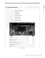
Upper Control Panel o DISPLAY FULL/FINE button O PHONES jack O POWER switch 0 PHONES level control PB level controls O REC level controls Audio level meters !Lf Jo • .nrao ear nue,or II II II I II .1010 ow • INT U SWIM MEM , II II O Indicators 0 MONITOR SELECT button a) INPUT SELECT button (j) AUDIO INPUT/MONITOR SELECT buttons ® VIDEO INPUT SELECT buttons REMOTE buttons Upper control panel 901E9SE Chapter 2 Location and Functions of Parts and Controls 2-3 2 1 1.
Upper Control Panel o DISPLAY FULL/FINE button O PHONES jack O POWER switch 0 PHONES level control PB level controls O REC level controls Audio level meters !Lf Jo • .nrao ear nue,or II II II I II .1010 ow • INT U SWIM MEM , II II O Indicators 0 MONITOR SELECT button a) INPUT SELECT button (j) AUDIO INPUT/MONITOR SELECT buttons ® VIDEO INPUT SELECT buttons REMOTE buttons Upper control panel 901E9SE Chapter 2 Location and Functions of Parts and Controls 2-3 2 1 1.
Operation Manual
Page 27
...and EJECT buttons. Press the button corresponding to the REMOTE 14N (9P)/OUT (9P) connectors control the VTR. COMPONENT (Y-R,B): The analog component video signal being input to the AUDIO INPUT (AES/EBU) connector is selected. When controlling the VTR from the MONITOR OUTPUT L and R connectors... 3-9. 2-5 Chapter 2 Location and Functions of the following buttons as required. 1 (9P) button: The external equipment connected to the video signal format. The button indicators flash when selected digital audio signals are disabled, except for recording VITC signals by the SET UP SELECT ...
...and EJECT buttons. Press the button corresponding to the REMOTE 14N (9P)/OUT (9P) connectors control the VTR. COMPONENT (Y-R,B): The analog component video signal being input to the AUDIO INPUT (AES/EBU) connector is selected. When controlling the VTR from the MONITOR OUTPUT L and R connectors... 3-9. 2-5 Chapter 2 Location and Functions of the following buttons as required. 1 (9P) button: The external equipment connected to the video signal format. The button indicators flash when selected digital audio signals are disabled, except for recording VITC signals by the SET UP SELECT ...
Operation Manual
Page 28
... pressed again. 2-6 Chapter 2 Location and Functions of Parts and Controls Lights steadly once the speeds have been memorized. O INSERT buttons Select the input signal channel (VIDEO, AUDIO CH-1, CH-2, CH-3, CH-4, CUE or TIME CODE) for insert edit. 2-1. Control Panel 2-1-2.
... pressed again. 2-6 Chapter 2 Location and Functions of Parts and Controls Lights steadly once the speeds have been memorized. O INSERT buttons Select the input signal channel (VIDEO, AUDIO CH-1, CH-2, CH-3, CH-4, CUE or TIME CODE) for insert edit. 2-1. Control Panel 2-1-2.
Operation Manual
Page 29
... flash. PLAYER button: When this VTR). If it lights to turn on the recorder monitor. Press one frame. The IN/OUT buttons are for setting video IN/OUT edit points and the AUDIO IN/OUT buttons are for audio IN/OUT' edit points. Press either of this VTR when this button... AUDIO OUT button. O AUDIO IN/OUT buttons Set the audio IN and OUT edit points separately from the video edit points. Press this button together with an external player VTR connected to monitor the video and audio currently being recorded by the editing buttons and tape transport buttons of the TRIM + / - If...
... flash. PLAYER button: When this VTR). If it lights to turn on the recorder monitor. Press one frame. The IN/OUT buttons are for setting video IN/OUT edit points and the AUDIO IN/OUT buttons are for audio IN/OUT' edit points. Press either of this VTR when this button... AUDIO OUT button. O AUDIO IN/OUT buttons Set the audio IN and OUT edit points separately from the video edit points. Press this button together with an external player VTR connected to monitor the video and audio currently being recorded by the editing buttons and tape transport buttons of the TRIM + / - If...
Operation Manual
Page 31
...and capstan servo lock. Pressing the STOP button while monitoring E-E signals returns you to the video and audio monitored before you to monitor E-E signals. This button flashes when the input video signal and the external reference signal are possible only when this button together with the PLAY ...of phase or when each signal is wound around the head-drum, but the head-drum continues to "1-10. Setup Menu" in the VIDEO INPUT and REF mode respectively. Pressing this button together with the ASSEMBLE or INSERT buttons. e) STOP button Stops the tape (stop mode ...
...and capstan servo lock. Pressing the STOP button while monitoring E-E signals returns you to the video and audio monitored before you to monitor E-E signals. This button flashes when the input video signal and the external reference signal are possible only when this button together with the PLAY ...of phase or when each signal is wound around the head-drum, but the head-drum continues to "1-10. Setup Menu" in the VIDEO INPUT and REF mode respectively. Pressing this button together with the ASSEMBLE or INSERT buttons. e) STOP button Stops the tape (stop mode ...

Operation Manual
Page 36
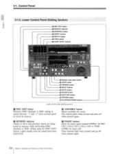
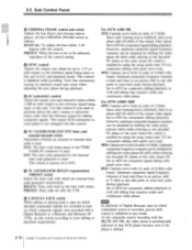
... GENERATOR REGEN/PRESET switch ® CAPSTAN LOCK switch Sub control panel EMPHASIS switch REC INHIBIT switch KEY INHIBIT switch OUT REF switch PROCESS CONTROL switch VIDEO control and switch CHROMA control and switch Photo: DVW-A500 GLnElin.1 2-14 Chapter 2 Location and Functions of Parts and Controls
... GENERATOR REGEN/PRESET switch ® CAPSTAN LOCK switch Sub control panel EMPHASIS switch REC INHIBIT switch KEY INHIBIT switch OUT REF switch PROCESS CONTROL switch VIDEO control and switch CHROMA control and switch Photo: DVW-A500 GLnElin.1 2-14 Chapter 2 Location and Functions of Parts and Controls

Operation Manual
Page 37
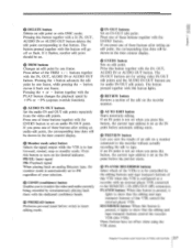
...To manually adjust thean setup level using the Y/C DELAY control. O BLACK LEVEL control and switch (for DVW-A500/500) Adjusts the setup level (black level). The setting of video signals by using the CHROMA control. Chapter 2 Location and Functions of analog Betacam or Betacam SP playback. ... to "1-10. O Y/C DELAY control and switch (for playback and digital audio recording. The setting of setup menu item 714. VIDEO connector as follows. Set the Y/C delay switch as the reference signal for DVW-A500/A500P only) Adjusts the Y/C delay of Parts and Controls 2-15
...To manually adjust thean setup level using the Y/C DELAY control. O BLACK LEVEL control and switch (for DVW-A500/500) Adjusts the setup level (black level). The setting of video signals by using the CHROMA control. Chapter 2 Location and Functions of analog Betacam or Betacam SP playback. ... to "1-10. O Y/C DELAY control and switch (for playback and digital audio recording. The setting of setup menu item 714. VIDEO connector as follows. Set the Y/C delay switch as the reference signal for DVW-A500/A500P only) Adjusts the Y/C delay of Parts and Controls 2-15
Operation Manual
Page 38
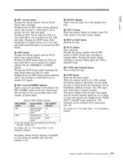
... Capstan servo locks in units of 2 fields. MANUAL: To adjust the hue within ± 200 ns with the control. For DVW-A500/500 2FD: Capstan servo locks in E-E and playback mode. Set to 2FD for component editing/playback. Note that requires stable and continuous... phase by using the setup menu item 712 for editing composite signals. However, optimum composite frequency response can be obtained by shifting the video phase (picture shift) while referring to your editing or playback requirements. Optimum composite frequency response can be obtained by using the setup menu...
... Capstan servo locks in units of 2 fields. MANUAL: To adjust the hue within ± 200 ns with the control. For DVW-A500/500 2FD: Capstan servo locks in E-E and playback mode. Set to 2FD for component editing/playback. Note that requires stable and continuous... phase by using the setup menu item 712 for editing composite signals. However, optimum composite frequency response can be obtained by shifting the video phase (picture shift) while referring to your editing or playback requirements. Optimum composite frequency response can be obtained by using the setup menu...
Operation Manual
Page 40
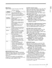
... code generator. Setup Menu" in the Installation Manual. O TC (time code) selector Determines whether the time code displayed in the input video signals are trademarks of Dolby Laboratories Licensing Corporation. 2-18 Chapter 2 Location and Functions of Parts and Controls O ID PRESET switch Sets the...NR Dolby noise reduction manufactured under license from Dolby Laboratories Licensing Corporation. If the TC GENERATOR REGEN/PRESET switch is used for DVW-A500/500 only) Selects whether the time code generator and CTL, counter advance in the set to ON. "DOLBY" and the double-D...
... code generator. Setup Menu" in the Installation Manual. O TC (time code) selector Determines whether the time code displayed in the input video signals are trademarks of Dolby Laboratories Licensing Corporation. 2-18 Chapter 2 Location and Functions of Parts and Controls O ID PRESET switch Sets the...NR Dolby noise reduction manufactured under license from Dolby Laboratories Licensing Corporation. If the TC GENERATOR REGEN/PRESET switch is used for DVW-A500/500 only) Selects whether the time code generator and CTL, counter advance in the set to ON. "DOLBY" and the double-D...


