Operating Instructions
Page 2
... a power supply source. WARNING This unit has no power switch. All interface cables used to connect peripherals must be shielded in this manual could void your Sony dealer regarding this equipment as a fire. The Authorized Representative for a Class A digital device, pursuant to the following two conditions: (1) this device may cause undesired operation. When installing the unit, incorporate a readily accessible disconnect device in which case the user...
... a power supply source. WARNING This unit has no power switch. All interface cables used to connect peripherals must be shielded in this manual could void your Sony dealer regarding this equipment as a fire. The Authorized Representative for a Class A digital device, pursuant to the following two conditions: (1) this device may cause undesired operation. When installing the unit, incorporate a readily accessible disconnect device in which case the user...
Operating Instructions
Page 3
... Remote Control Unit 22 EXPOSURE Menu 23 COLOR Menu 24 PICTURE Menu 25 FOCUS Menu 26 PAN TILT ZOOM Menu 27 SYSTEM Menu 28 VIDEO OUT Menu 29 STATUS Menu 30 Operation Using the Supplied Remote Commander Turning on the Power 31 Pan/Tilt and Zoom Operation 32 Panning and Tilting 32 Zooming 33 Operating Multiple Cameras with the Remote Commander 33 Adjusting the Camera 33 Focusing on a Subject 39 Shooting with Back Lighting 40 Adjusting the White Balance 40 Adjusting the Brightness 40 Storing the Camera Settings in a High Position ..........44 Connections 51 Connecting...
... Remote Control Unit 22 EXPOSURE Menu 23 COLOR Menu 24 PICTURE Menu 25 FOCUS Menu 26 PAN TILT ZOOM Menu 27 SYSTEM Menu 28 VIDEO OUT Menu 29 STATUS Menu 30 Operation Using the Supplied Remote Commander Turning on the Power 31 Pan/Tilt and Zoom Operation 32 Panning and Tilting 32 Zooming 33 Operating Multiple Cameras with the Remote Commander 33 Adjusting the Camera 33 Focusing on a Subject 39 Shooting with Back Lighting 40 Adjusting the White Balance 40 Adjusting the Brightness 40 Storing the Camera Settings in a High Position ..........44 Connections 51 Connecting...

Operating Instructions
Page 7
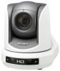
... connected and remotely controlled at a high communication speed of 38,400 bps. • The optional RM-BR300 Remote Control Unit allows easy camera operations. Built-in interface card slot The camera is equipped with an external video sync function to 7 cameras can be selected with an HD camera block, pan/tilt mechanism, and 18-magnification optical/4-magnification digital zoom lens in a compact body. As the camera supports the industry-standard VISCA camera protocol...
... connected and remotely controlled at a high communication speed of 38,400 bps. • The optional RM-BR300 Remote Control Unit allows easy camera operations. Built-in interface card slot The camera is equipped with an external video sync function to 7 cameras can be selected with an HD camera block, pan/tilt mechanism, and 18-magnification optical/4-magnification digital zoom lens in a compact body. As the camera supports the industry-standard VISCA camera protocol...
Operating Instructions
Page 9
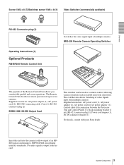
...Remote Control Unit It switches the video signal input of up to SMPTE292M serial digital interface standardss. The Remote Control Unit also allows remote operation of multiple cameras. The switcher also allows switching of the Remote Control Unit allows you comfortable pan/tilt and zoom operations. No audio signal is output from multiple cameras. Supplied accessories: AC power cord (1), AC power adaptor (1), AC power cord for AC power adaptor (1), Control cable (for connection between the Processor Unit and Control Panel) (1), Rack mounting bracket (1 set), RS-422 connector plug...
...Remote Control Unit It switches the video signal input of up to SMPTE292M serial digital interface standardss. The Remote Control Unit also allows remote operation of multiple cameras. The switcher also allows switching of the Remote Control Unit allows you comfortable pan/tilt and zoom operations. No audio signal is output from multiple cameras. Supplied accessories: AC power cord (1), AC power adaptor (1), AC power cord for AC power adaptor (1), Control cable (for connection between the Processor Unit and Control Panel) (1), Rack mounting bracket (1 set), RS-422 connector plug...
Operating Instructions
Page 14
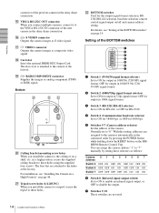
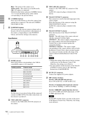
...-HD2 Output Card. in a high position, secure the supplied ceiling bracket to the cameras automatically in the daisy chain connection. V BOTTOM switches Used for 9600 bps. 5 Switches 5-7 (Camera address selector) Set the address of the camera. With this setting, addresses are assigned to these holes. You can assign the camera address "1" to "7" manually by pressing the POWER button while holding down the RESET button on the RMBR300 Remote Control Unit. S RGB/COMPONENT connector Supplies the images as composite video signal. Bottom w; Setting of...
...-HD2 Output Card. in a high position, secure the supplied ceiling bracket to the cameras automatically in the daisy chain connection. V BOTTOM switches Used for 9600 bps. 5 Switches 5-7 (Camera address selector) Set the address of the camera. With this setting, addresses are assigned to these holes. You can assign the camera address "1" to "7" manually by pressing the POWER button while holding down the RESET button on the RMBR300 Remote Control Unit. S RGB/COMPONENT connector Supplies the images as composite video signal. Bottom w; Setting of...

Operating Instructions
Page 15
... • Set the switches before you turn on the power of the camera. • You cannot use V or v to select the menu items and B or b to disable the backlight compensation. The camera number can be set values. B FOCUS buttons Used for focus adjustment. C DATA SCREEN button Press this button to reset the pan/tilt position. If you press the button when a lower-level menu is connected to zoom quickly. When the menu is displayed. Press it again to operate with...
... • Set the switches before you turn on the power of the camera. • You cannot use V or v to select the menu items and B or b to disable the backlight compensation. The camera number can be set values. B FOCUS buttons Used for focus adjustment. C DATA SCREEN button Press this button to reset the pan/tilt position. If you press the button when a lower-level menu is connected to zoom quickly. When the menu is displayed. Press it again to operate with...
Operating Instructions
Page 16
... R and B controls" on the camera. Press the LOCK button for more than one second again to the white balance mode selected on page 40. When you dispose of explosion, use R6 (size AA) manganese or alkaline batteries. Front 890qaqsqd qf 1 2 3 4 5 6 7 VALUE LOCK - + R BRIGHT MODE - + B FOCUS AUTO AUTO MANUAL NEAR FAR ONE PUSH AF RESET PRESET SHIFT L/R DIRECTION POWER PANEL LIGHT BLACK PAN-TILT ONE PUSH LIGHT RESET AWB MENU POSITION 12345678...
... R and B controls" on the camera. Press the LOCK button for more than one second again to the white balance mode selected on page 40. When you dispose of explosion, use R6 (size AA) manganese or alkaline batteries. Front 890qaqsqd qf 1 2 3 4 5 6 7 VALUE LOCK - + R BRIGHT MODE - + B FOCUS AUTO AUTO MANUAL NEAR FAR ONE PUSH AF RESET PRESET SHIFT L/R DIRECTION POWER PANEL LIGHT BLACK PAN-TILT ONE PUSH LIGHT RESET AWB MENU POSITION 12345678...
Operating Instructions
Page 17
... pressed POSITION button is used for about one -push auto focus function. To disable the spotlight compensation, hold down this button and press one of the supplied Remote Commander. L PAN-TILT RESET button Press this button to reset the pan/tilt position of the camera to the angle of the PAN TILT ZOOM menu setting, the pan/tilt/zoom are connected, hold down this button and press POSITION button 1 (STD). N MENU button Press this button for menu operations. When you turn the dial on the upper part...
... pressed POSITION button is used for about one -push auto focus function. To disable the spotlight compensation, hold down this button and press one of the supplied Remote Commander. L PAN-TILT RESET button Press this button to reset the pan/tilt position of the camera to the angle of the PAN TILT ZOOM menu setting, the pan/tilt/zoom are connected, hold down this button and press POSITION button 1 (STD). N MENU button Press this button for menu operations. When you turn the dial on the upper part...
Operating Instructions
Page 18
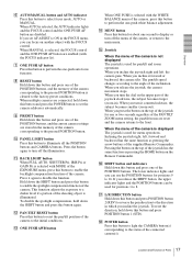
... U MODE selector Select the position corresponding to the VISCAcontrollable camera to select the camera from among those connected. V VISCA RS-232C connector Connect to the VISCA RS-422 connector of the camera. An RS-422 connector plug is in blue. Notes • Change the setting of the selector before you turn on the power for the Remote Control Unit. wh DC IN 12V connector Connect the supplied AC power adaptor. The selected CAMERA button lights...
... U MODE selector Select the position corresponding to the VISCAcontrollable camera to select the camera from among those connected. V VISCA RS-232C connector Connect to the VISCA RS-422 connector of the camera. An RS-422 connector plug is in blue. Notes • Change the setting of the selector before you turn on the power for the Remote Control Unit. wh DC IN 12V connector Connect the supplied AC power adaptor. The selected CAMERA button lights...
Operating Instructions
Page 20
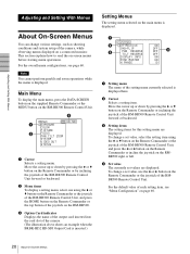
... the joystick of the RM-BR300 Remote Control Unit, and press the B or b button on the Remote Commander or incline the joystick on the RMBR300 right or left. 4 Set value The currently set value, use the B or b button on a connected monitor. This section explains how to read the on the RM-BR300 Remote Control Unit. >EXPOSURE COLOR PICTURE FOCUS PAN TILT ZOOM SYSTEM VIDEO OUT STATUS HD-SDI 1 Cursor Selects a setting menu.
... the joystick of the RM-BR300 Remote Control Unit, and press the B or b button on the Remote Commander or incline the joystick on the RMBR300 right or left. 4 Set value The currently set value, use the B or b button on a connected monitor. This section explains how to read the on the RM-BR300 Remote Control Unit. >EXPOSURE COLOR PICTURE FOCUS PAN TILT ZOOM SYSTEM VIDEO OUT STATUS HD-SDI 1 Cursor Selects a setting menu.
Operating Instructions
Page 21
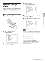
...Menu Operation Using the Supplied Remote Commander 1 POWER CAMERA SELECT 2 1 FOCUS 3 MANUAL NEAR BACK LIGHT FAR AUTO DATA SCREEN 3 REV 2 6 STD RESET 1 4 5 PRESET POSITIOPNAN-TILT HOME 2,4 SLOW 5 ZOOM PARNE-TSIELTT FAST T T W DIREL/CRTION SET 3 W RM-EV100 1 Press the DATA SCREEN button. To set IR-RECEIVE in the SYSTEM menu to operate the menu using the supplied Remote Commander, or using the RM-BR300 Remote Control Unit (not supplied). If a lower-level menu is displayed, press the DATA SCREEN button once. IR-RECEIVE ON IMG-FLIP OFF PAN REVERSE OFF TILT...
...Menu Operation Using the Supplied Remote Commander 1 POWER CAMERA SELECT 2 1 FOCUS 3 MANUAL NEAR BACK LIGHT FAR AUTO DATA SCREEN 3 REV 2 6 STD RESET 1 4 5 PRESET POSITIOPNAN-TILT HOME 2,4 SLOW 5 ZOOM PARNE-TSIELTT FAST T T W DIREL/CRTION SET 3 W RM-EV100 1 Press the DATA SCREEN button. To set IR-RECEIVE in the SYSTEM menu to operate the menu using the supplied Remote Commander, or using the RM-BR300 Remote Control Unit (not supplied). If a lower-level menu is displayed, press the DATA SCREEN button once. IR-RECEIVE ON IMG-FLIP OFF PAN REVERSE OFF TILT...
Operating Instructions
Page 22
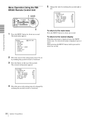
... second. Adjusting and Setting With Menus Menu Operation Using the RMBR300 Remote Control Unit 1 2,4,5 VALUE LOCK - + R BRIGHT MODE - + B FOCUS AUTO AUTO MANUAL NEAR FAR ONE PUSH AF RESET PRESET SHIFT L/R DIRECTION POWER PANEL LIGHT BLACK PAN-TILT ONE PUSH LIGHT RESET AWB MENU POSITION 12345678 9 10 11 12 13 14 15 16 STD REV CAMERA 1234567 3 1 Press the MENU button for about one second. If a lower-level menu is displayed, press the MENU button once. To return to be changed by...
... second. Adjusting and Setting With Menus Menu Operation Using the RMBR300 Remote Control Unit 1 2,4,5 VALUE LOCK - + R BRIGHT MODE - + B FOCUS AUTO AUTO MANUAL NEAR FAR ONE PUSH AF RESET PRESET SHIFT L/R DIRECTION POWER PANEL LIGHT BLACK PAN-TILT ONE PUSH LIGHT RESET AWB MENU POSITION 12345678 9 10 11 12 13 14 15 16 STD REV CAMERA 1234567 3 1 Press the MENU button for about one second. If a lower-level menu is displayed, press the MENU button once. To return to be changed by...
Operating Instructions
Page 28
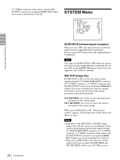
.../OFF setting, images shot with pan/tilt operations. SYSTEM Menu >IR-RECEIVE ON IMG-FLIP OFF PAN REVERSE OFF TILT REVERSE OFF DISPLAY INFO ON SYNC MASTER HD H PHASE 10 Adjusting and Setting With Menus 28 SYSTEM Menu IR-RECEIVE (infrared signal reception) When it to OFF, use the supplied Remote Commander. VIDEO connector of the camera, and the SDI OUTPUT connector of an optional BRBK-HD2 Output Card, if one is installed in a card slot...
.../OFF setting, images shot with pan/tilt operations. SYSTEM Menu >IR-RECEIVE ON IMG-FLIP OFF PAN REVERSE OFF TILT REVERSE OFF DISPLAY INFO ON SYNC MASTER HD H PHASE 10 Adjusting and Setting With Menus 28 SYSTEM Menu IR-RECEIVE (infrared signal reception) When it to OFF, use the supplied Remote Commander. VIDEO connector of the camera, and the SDI OUTPUT connector of an optional BRBK-HD2 Output Card, if one is installed in a card slot...
Operating Instructions
Page 31
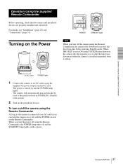
... camera will automatically pan and tilt and be reset to an AC outlet, you turn the power off using the supplied AC power adaptor and power cord. When you can turn off with the POWER switch on the Power When IMG-FLIP is set to an AC outlet using the Remote Commander, the POWER lamp turns off and the STANDBY lamp lights on the camera. 31 Turning on the Remote Commander. POWER CAMERA SELECT 1 2 3 AUTO FOCUS MANUAL FAR...
... camera will automatically pan and tilt and be reset to an AC outlet, you turn the power off using the supplied AC power adaptor and power cord. When you can turn off with the POWER switch on the Power When IMG-FLIP is set to an AC outlet using the Remote Commander, the POWER lamp turns off and the STANDBY lamp lights on the camera. 31 Turning on the Remote Commander. POWER CAMERA SELECT 1 2 3 AUTO FOCUS MANUAL FAR...
Operating Instructions
Page 34
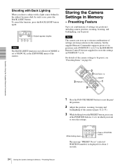
... page 64. Operation Using the Supplied Remote Commander Shooting with a light source behind it, the subject becomes dark. Storing the Camera Settings in which you shoot a subject with Back Lighting When you want to store the settings. AUTO FOCUS MANUAL FAR NEAR DATA SCREEN BACK LIGHT STD REV 123 Subject appears brighter. POWER CAMERA SELECT 2 1 FOCUS FAR 3 MANUAL NEAR BACK LIGHT 2 3 POSITION 1-6 AUTO DATA SCREEN 3 PRESET 3 REV 2 6 STD RESET 1 4 5 PRESET POSITIOPNAN-TILT HOME PARNE-TSIELTT FAST RESET 1 ZOOM T 2 T SLOW...
... page 64. Operation Using the Supplied Remote Commander Shooting with a light source behind it, the subject becomes dark. Storing the Camera Settings in which you shoot a subject with Back Lighting When you want to store the settings. AUTO FOCUS MANUAL FAR NEAR DATA SCREEN BACK LIGHT STD REV 123 Subject appears brighter. POWER CAMERA SELECT 2 1 FOCUS FAR 3 MANUAL NEAR BACK LIGHT 2 3 POSITION 1-6 AUTO DATA SCREEN 3 PRESET 3 REV 2 6 STD RESET 1 4 5 PRESET POSITIOPNAN-TILT HOME PARNE-TSIELTT FAST RESET 1 ZOOM T 2 T SLOW...
Operating Instructions
Page 36
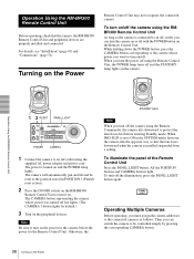
... camera. Operation Using the RM-BR300 Remote Control Unit Before operating, check that the lens faces downward when the camera is installed suspended from dust before the power for the Remote Control Unit. Turning on and the POWER lamp lights. For details, see "Installation" (page 43) and "Connections" (page 51). Operation Using the RM-BR300 Remote Control Unit 1 2 RESET PANEL LIGHT VALUE LOCK - + R BRIGHT MODE - + B FOCUS AUTO AUTO MANUAL NEAR ONE PUSH FAR AF RESET PRESET SHIFT L/R DIRECTION POWER PANEL LIGHT BLACK PAN-TILT ONE PUSH LIGHT RESET AWB MENU POSITION...
... camera. Operation Using the RM-BR300 Remote Control Unit Before operating, check that the lens faces downward when the camera is installed suspended from dust before the power for the Remote Control Unit. Turning on and the POWER lamp lights. For details, see "Installation" (page 43) and "Connections" (page 51). Operation Using the RM-BR300 Remote Control Unit 1 2 RESET PANEL LIGHT VALUE LOCK - + R BRIGHT MODE - + B FOCUS AUTO AUTO MANUAL NEAR ONE PUSH FAR AF RESET PRESET SHIFT L/R DIRECTION POWER PANEL LIGHT BLACK PAN-TILT ONE PUSH LIGHT RESET AWB MENU POSITION...
Operating Instructions
Page 37
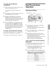
... camera is set , as shown in the table below. The Remote Control Unit recognizes the connected cameras and assigns them camera addresses 1 to 7, using the camera address selectors on the maximum panning/ tilting speed You can switch the camera you want to stop panning/tilting. Pan/Tilt and Zoom Operation Panning and Tilting L/R DIRECTION REV 1 STD PAN-TILT RESET VALUE LOCK - + R BRIGHT MODE - + B FOCUS AUTO AUTO MANUAL NEAR FAR ONE PUSH AF RESET PRESET SHIFT L/R DIRECTION POWER PANEL LIGHT BLACK LIGHT PAN-TILT ONE PUSH RESET AWB MENU POSITION 12345678...
... camera is set , as shown in the table below. The Remote Control Unit recognizes the connected cameras and assigns them camera addresses 1 to 7, using the camera address selectors on the maximum panning/ tilting speed You can switch the camera you want to stop panning/tilting. Pan/Tilt and Zoom Operation Panning and Tilting L/R DIRECTION REV 1 STD PAN-TILT RESET VALUE LOCK - + R BRIGHT MODE - + B FOCUS AUTO AUTO MANUAL NEAR FAR ONE PUSH AF RESET PRESET SHIFT L/R DIRECTION POWER PANEL LIGHT BLACK LIGHT PAN-TILT ONE PUSH RESET AWB MENU POSITION 12345678...
Operating Instructions
Page 41
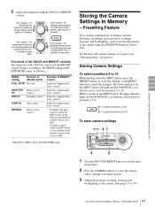
... of the Remote Control Unit is ON in the EXPOSURE menu Storing the Camera Settings in Memory - When you want to preset. 3 Adjust the position, zooming, focusing and backlighting of the camera settings to 39.) 41 Storing the Camera Settings in Memory - Turn toward - Presetting Feature Up to 8. To store camera settings RESET 4 1 VALUE LOCK - + R BRIGHT MODE - + B FOCUS AUTO AUTO MANUAL NEAR FAR ONE PUSH AF RESET PRESET SHIFT L/R DIRECTION POWER PANEL LIGHT BLACK LIGHT PAN-TILT ONE PUSH RESET AWB MENU POSITION 12345678 9 10...
... of the Remote Control Unit is ON in the EXPOSURE menu Storing the Camera Settings in Memory - When you want to preset. 3 Adjust the position, zooming, focusing and backlighting of the camera settings to 39.) 41 Storing the Camera Settings in Memory - Turn toward - Presetting Feature Up to 8. To store camera settings RESET 4 1 VALUE LOCK - + R BRIGHT MODE - + B FOCUS AUTO AUTO MANUAL NEAR FAR ONE PUSH AF RESET PRESET SHIFT L/R DIRECTION POWER PANEL LIGHT BLACK LIGHT PAN-TILT ONE PUSH RESET AWB MENU POSITION 12345678 9 10...
Operating Instructions
Page 44
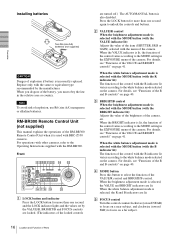
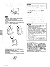
... screws of the following specifications. 1/4 -20UNC Installing the Camera in a High Position Using the supplied ceiling brackets, wire rope, and screws, you attach the camera to a ceiling or shelf, etc. firmly, after deciding the shooting direction. = 4.5 - 7 mm = 0.18 - 0.27 inches Installation and Connections 44 Installation Notes • You should not be passed through the ceiling bracket (A). When you install the camera, always install it on a shelf...
... screws of the following specifications. 1/4 -20UNC Installing the Camera in a High Position Using the supplied ceiling brackets, wire rope, and screws, you attach the camera to a ceiling or shelf, etc. firmly, after deciding the shooting direction. = 4.5 - 7 mm = 0.18 - 0.27 inches Installation and Connections 44 Installation Notes • You should not be passed through the ceiling bracket (A). When you install the camera, always install it on a shelf...
Operating Instructions
Page 58
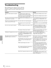
... the camera and video monitor. Change the PAN-TILT LIMIT setting in the EXPOSURE menu. Press the CAMERA SELECT button corresponding to turn off the menu from the monitor screen. VISCA control setting is displayed on the video The video cable is not connected properly. The NC (No Connection) switch is set IR-RECEIVE to ON. go . Press the DATA SCREEN button on the supplied Remote Commander or the MENU button on the RM-BR300 Remote Control Unit to the IR SELECT switch setting on the Remote Control Unit...
... the camera and video monitor. Change the PAN-TILT LIMIT setting in the EXPOSURE menu. Press the CAMERA SELECT button corresponding to turn off the menu from the monitor screen. VISCA control setting is displayed on the video The video cable is not connected properly. The NC (No Connection) switch is set IR-RECEIVE to ON. go . Press the DATA SCREEN button on the supplied Remote Commander or the MENU button on the RM-BR300 Remote Control Unit to the IR SELECT switch setting on the Remote Control Unit...


