
Service Manual
Page 1
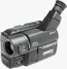
... Kong Model CCD-TRV16/TRV46 Taiwan Model CCD-TRV16 Brazilian Model CCD-TR315/TR416 CCD-TRV16 B MECHANISM Photo : CCD-TRV46 NTSC SPECIFICATIONS For MECHANISM ADJUSTMENTS, refer to 100,000 lux Recommended illumination More than 100 lux * Object invisible for the dark can be shot with infrared lighting. cassette) Approx. 5 min. Video camera recorder System Video recording system 2 Rotary heads Helical scanning FM system Audio recording system Rotary heads, FM system Video signal NTSC color, EIA standards Usable cassette 8mm video format cassette CCD-TR315...
... Kong Model CCD-TRV16/TRV46 Taiwan Model CCD-TRV16 Brazilian Model CCD-TR315/TR416 CCD-TRV16 B MECHANISM Photo : CCD-TRV46 NTSC SPECIFICATIONS For MECHANISM ADJUSTMENTS, refer to 100,000 lux Recommended illumination More than 100 lux * Object invisible for the dark can be shot with infrared lighting. cassette) Approx. 5 min. Video camera recorder System Video recording system 2 Rotary heads Helical scanning FM system Audio recording system Rotary heads, FM system Video signal NTSC color, EIA standards Usable cassette 8mm video format cassette CCD-TR315...
Service Manual
Page 2
...) LANC control jack Stereo mini-minijack (ø 2.5 mm) MIC jack Mini jack, 0.388mV low impedance with 2.5 to 3.0 V DC, output impedance 6.8 kilohms (ø 3.5 mm) : Monaural type Speaker (TRV series only) Dynamic speaker General Power requirements 7.2 V (battery pack) 8.4 V (AC power adaptor) Averege power consumption(when using the battery pack) During camera recording CCD-TR416/TR416PK/TR516/ TR516PK : 2.4 W CCD-TR315/TR716 : 2.5 W During camera recording using LCD CCD-TRV16/TRV16PK/TRV36/ TRV36PK : 3.1 W CCD-TRV43/TRV46/TRV46PK : 3.2 W Viewfinder CCD-TRV16/TRV16PK...
...) LANC control jack Stereo mini-minijack (ø 2.5 mm) MIC jack Mini jack, 0.388mV low impedance with 2.5 to 3.0 V DC, output impedance 6.8 kilohms (ø 3.5 mm) : Monaural type Speaker (TRV series only) Dynamic speaker General Power requirements 7.2 V (battery pack) 8.4 V (AC power adaptor) Averege power consumption(when using the battery pack) During camera recording CCD-TR416/TR416PK/TR516/ TR516PK : 2.4 W CCD-TR315/TR716 : 2.5 W During camera recording using LCD CCD-TRV16/TRV16PK/TRV36/ TRV36PK : 3.1 W CCD-TRV43/TRV46/TRV46PK : 3.2 W Viewfinder CCD-TRV16/TRV16PK...
Service Manual
Page 7
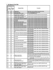
... operations from the beginning. Remove the battery or power cable, connect, and perform operations from the beginning. Inspect the lens block focus reset sensor (Pin !ª of CN551 of VC-215 board) when focusing is performed when the focus dial is rotated in the Difficult to adjust focus E 6 1 0 0 (Cannot initialize focus.) focus manual mode and the focus motor drive circuit (IC552 of VC215 board) when zooming is not performed. Note : Use the remote...
... operations from the beginning. Remove the battery or power cable, connect, and perform operations from the beginning. Inspect the lens block focus reset sensor (Pin !ª of CN551 of VC-215 board) when focusing is performed when the focus dial is rotated in the Difficult to adjust focus E 6 1 0 0 (Cannot initialize focus.) focus manual mode and the focus motor drive circuit (IC552 of VC215 board) when zooming is not performed. Note : Use the remote...
Service Manual
Page 8
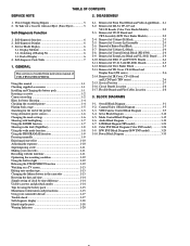
...17 Truoble check 1-17 Self-diagnosis display 1-18 Identifying the parts 1-18 Warning Indicators 1-20 2-1. Color EVF Block Diagram (Color EVF model 3-26 3-9. Using this manual 1-1 Checking supplied accessories 1-1 Installing and Charging the battery pack 1-1 Inserting a cassette 1-2 Camera recording 1-2 Hints for better Shooting 1-4 Checking the recorded picture 1-4 Playing back a tape 1-5 Searching for the end of the picture 1-5 Using alternative power sources 1-6 Changing the mode settings 1-6 Shooting with backlighting 1-7 Using the FADER function 1-7 Shooting in...
...17 Truoble check 1-17 Self-diagnosis display 1-18 Identifying the parts 1-18 Warning Indicators 1-20 2-1. Color EVF Block Diagram (Color EVF model 3-26 3-9. Using this manual 1-1 Checking supplied accessories 1-1 Installing and Charging the battery pack 1-1 Inserting a cassette 1-2 Camera recording 1-2 Hints for better Shooting 1-4 Checking the recorded picture 1-4 Playing back a tape 1-5 Searching for the end of the picture 1-5 Using alternative power sources 1-6 Changing the mode settings 1-6 Shooting with backlighting 1-7 Using the FADER function 1-7 Shooting in...
Service Manual
Page 10
...Hi8) switching (Hi8 model 5-39 3-1-8. Service Mode 5-39 1. Emergency memory address 5-40 2-1. Bit value discrimination 5-42 4. Input/output selection check 5-43 8. Filter f0 Adjustment (VC-215 board 5-48 4. Exploded Views 6-1 6-1-1. Clolor EVF Block Assembly (CCD-TR416/TR416PK/TR516/TR516PK/TR716) ..... 6-7 6-1-8. Tape path Adjustment 5-34 1. Equipments to be Used 5-35 3-1-2. Test mode setting 5-39 2. System Control System Adjustment 5-45 1. Initialization of use check 5-44 3-2. Standerd8 REC Y Current Adjustment (VC-215 board) (CCD-TR315/TR416/TR416PK CCD-TRV16...
...Hi8) switching (Hi8 model 5-39 3-1-8. Service Mode 5-39 1. Emergency memory address 5-40 2-1. Bit value discrimination 5-42 4. Input/output selection check 5-43 8. Filter f0 Adjustment (VC-215 board 5-48 4. Exploded Views 6-1 6-1-1. Clolor EVF Block Assembly (CCD-TR416/TR416PK/TR516/TR516PK/TR716) ..... 6-7 6-1-8. Tape path Adjustment 5-34 1. Equipments to be Used 5-35 3-1-2. Test mode setting 5-39 2. System Control System Adjustment 5-45 1. Initialization of use check 5-44 3-2. Standerd8 REC Y Current Adjustment (VC-215 board) (CCD-TR315/TR416/TR416PK CCD-TRV16...
Service Manual
Page 31
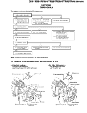
.../TRV43/TRV46/TRV46PK -No video light models- LB-54/VF-119 & 120 BOARDS (Color view finder models only) 2-3. REMOVAL OF FRONT PANEL BLOCK AND VIDEO LIGHT BLOCK -Video light models- CCD-TR315/TR416/TR416PK/TR516/TR516PK/TR716 CCD-TRV16/TRV16PK/TRV36/TRV36PK/TRV43/TRV46/TRV46PK SECTION 2 DISASSEMBLY The equipment can be removed using the following procedure. VIDEO CAMERA RECORDER 2-1. CABINET (L) BLOCK 2-13. ZOOM LENS BLOCK VL-21/22 BOARD 2-8. CONTROL SWITCH BLOCK (FK-8500...
.../TRV43/TRV46/TRV46PK -No video light models- LB-54/VF-119 & 120 BOARDS (Color view finder models only) 2-3. REMOVAL OF FRONT PANEL BLOCK AND VIDEO LIGHT BLOCK -Video light models- CCD-TR315/TR416/TR416PK/TR516/TR516PK/TR716 CCD-TRV16/TRV16PK/TRV36/TRV36PK/TRV43/TRV46/TRV46PK SECTION 2 DISASSEMBLY The equipment can be removed using the following procedure. VIDEO CAMERA RECORDER 2-1. CABINET (L) BLOCK 2-13. ZOOM LENS BLOCK VL-21/22 BOARD 2-8. CONTROL SWITCH BLOCK (FK-8500...
Service Manual
Page 83
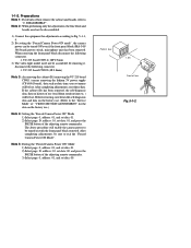
... Camera Power ON Mode". After completing adjustments, reset these data. VC-215 board CN916 (18P 0.5mm) 3) The video light model need not be disassembled. 1) Connect the equipment for the data on the history use .) Note 4: Setting the "Forced Camera Power ON" Mode 1) Select page: 0, address: 01, and set data: 01. 2) Select page: D, address: 10, set data: 00. 1-1-2. DISASSEMBLY". Before removing, note down the self-diagnosis data and data on the history use . (Refer to the "Service Mode...
... Camera Power ON Mode". After completing adjustments, reset these data. VC-215 board CN916 (18P 0.5mm) 3) The video light model need not be disassembled. 1) Connect the equipment for the data on the history use .) Note 4: Setting the "Forced Camera Power ON" Mode 1) Select page: 0, address: 01, and set data: 01. 2) Select page: D, address: 10, set data: 00. 1-1-2. DISASSEMBLY". Before removing, note down the self-diagnosis data and data on the history use . (Refer to the "Service Mode...
Service Manual
Page 86
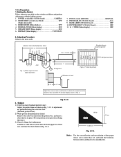
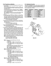
... monitor picture) A B Adjust the camera zoom and direction to be smoothly flat. PROGRAM AE (CF-60/61 board Auto 9. Adjusting Procedure Adjust in Fig. 5-1-5. FOCUS switch (MF-8500 MANUAL 8. PICTURE EFECT (CF-60/61 board OFF 11. 16 : 9 WIDE (Menu display OFF 2. Black White 1189 mm 841 mm Fig. 5-1-6. 1-1-3.Precaution 1. NIGHT SHOT switch (Lens Block OFF (Night shot model) 3. a. (Video output terminal output wavefom) BA V Enlargement Difference in Fig. BACK LIGHT (CF-60...
... monitor picture) A B Adjust the camera zoom and direction to be smoothly flat. PROGRAM AE (CF-60/61 board Auto 9. Adjusting Procedure Adjust in Fig. 5-1-5. FOCUS switch (MF-8500 MANUAL 8. PICTURE EFECT (CF-60/61 board OFF 11. 16 : 9 WIDE (Menu display OFF 2. Black White 1189 mm 841 mm Fig. 5-1-6. 1-1-3.Precaution 1. NIGHT SHOT switch (Lens Block OFF (Night shot model) 3. a. (Video output terminal output wavefom) BA V Enlargement Difference in Fig. BACK LIGHT (CF-60...
Service Manual
Page 117
To set to the VTR mode, set the power switch to the "Service Mode" for the data on history of use .) To remove the cabinet (R), disconnect the following connectors. 1. VC-215 board CN916 (18P 0.5mm) 3) The lens block (CD-210/211 board) need not be connected. cept during battery end adjustment. VC-215 board CN909 (4P 0.8mm) 5) Cabinet (R) ( Camera function switch (CF-60/61board), LCD block, viewfinder) need not be operate even...
To set to the VTR mode, set the power switch to the "Service Mode" for the data on history of use .) To remove the cabinet (R), disconnect the following connectors. 1. VC-215 board CN916 (18P 0.5mm) 3) The lens block (CD-210/211 board) need not be connected. cept during battery end adjustment. VC-215 board CN909 (4P 0.8mm) 5) Cabinet (R) ( Camera function switch (CF-60/61board), LCD block, viewfinder) need not be operate even...
Service Manual
Page 126
... Measuring Instrument Adjustment Page Adjustment Address Camera recording Arbitrary LCD display of the battery will also be connected. "Hexadecimal-decimal conversion table") 12) Calculate D31', D32', D33' and D34' using following equations (decimal calculation), convert it to a hexadecimal number, and input each data, be sure to Table 5-1-2. Switch setting 1) AUTO FOCUS OFF 2) LCD screen Closed 3) NIGHT SHOT OFF 4) VIDEO LIGHT OFF (VIDEO LIGHT model) Connection: 1) Connect the regulated power supply and the digital voltmeter to the camera recording mode. 6) Select...
... Measuring Instrument Adjustment Page Adjustment Address Camera recording Arbitrary LCD display of the battery will also be connected. "Hexadecimal-decimal conversion table") 12) Calculate D31', D32', D33' and D34' using following equations (decimal calculation), convert it to a hexadecimal number, and input each data, be sure to Table 5-1-2. Switch setting 1) AUTO FOCUS OFF 2) LCD screen Closed 3) NIGHT SHOT OFF 4) VIDEO LIGHT OFF (VIDEO LIGHT model) Connection: 1) Connect the regulated power supply and the digital voltmeter to the camera recording mode. 6) Select...
Service Manual
Page 132
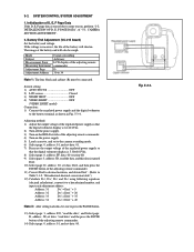
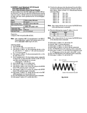
...) Press the PAUSE button of bit1 to "1". (Refer to Table 5-1-2. 7. Service mode"). 3) Select page: D, address: 15, after memorizing the data , set the bit value of bit7 to "0". 4) Set to recording mode. (Use the wireless remote commander of 8mm VCR, or connect Pin 6 of CN935 of DD-117 board and GND with 4.7kΩ registor for the model without REC switch". 21) Press the PAUSE button of the adjusting remote commander...
...) Press the PAUSE button of bit1 to "1". (Refer to Table 5-1-2. 7. Service mode"). 3) Select page: D, address: 15, after memorizing the data , set the bit value of bit7 to "0". 4) Set to recording mode. (Use the wireless remote commander of 8mm VCR, or connect Pin 6 of CN935 of DD-117 board and GND with 4.7kΩ registor for the model without REC switch". 21) Press the PAUSE button of the adjusting remote commander...
Service Manual
Page 133
... down the data , set data: FF, and press the PAUSE button of the adjusting remote commander. 8) Select page: F, address: 65, after memorizing the data, set the bit value of the adjusting remote commander. 24) Select page: 0, address: 01, and set to "3. Service mode"). 3) Select page: D, address: 15, after memorizing the data , set the bit value of bit7 to "0". 4) Set to recording mode. (Use the wireless remote commander of 8mm VCR, or connect Pin...
... down the data , set data: FF, and press the PAUSE button of the adjusting remote commander. 8) Select page: F, address: 65, after memorizing the data, set the bit value of the adjusting remote commander. 24) Select page: 0, address: 01, and set to "3. Service mode"). 3) Select page: D, address: 15, after memorizing the data , set the bit value of bit7 to "0". 4) Set to recording mode. (Use the wireless remote commander of 8mm VCR, or connect Pin...
Service Manual
Page 134
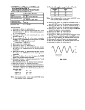
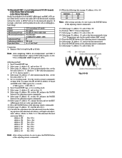
... model without REC switch". 21) Press the PAUSE button of the adjusting remote commander. 12) Select page: F, address: 5C, read the data (D5C). 13) Calculate the adjustment data (hexadecimal) from the follow- Bit value discrimination" of the REC AFM signal and REC ATF signal. If too high, color beets will not be produced on the self-recording/playback image. Address 63 64 Data 7C 7C Note: After setting...
... model without REC switch". 21) Press the PAUSE button of the adjusting remote commander. 12) Select page: F, address: 5C, read the data (D5C). 13) Calculate the adjustment data (hexadecimal) from the follow- Bit value discrimination" of the REC AFM signal and REC ATF signal. If too high, color beets will not be produced on the self-recording/playback image. Address 63 64 Data 7C 7C Note: After setting...
Service Manual
Page 135
... "REC L Level Adjustment" and "REC C Current Adjustment", replace C085 with 4.7kΩ registor for the model without REC switch". 19) Press the PAUSE button of the adjusting remote commander. 20) Select page: D, address: 15, and set the data memorized. 21) Press the PAUSE button of the adjusting remote commander. 22) Select page: 0, address: 01, and set the bit value of bit7 to "0". 5) Set to recording mode. (Use the wireless remote commander of 8mm VCR, or connect Pin...
... "REC L Level Adjustment" and "REC C Current Adjustment", replace C085 with 4.7kΩ registor for the model without REC switch". 19) Press the PAUSE button of the adjusting remote commander. 20) Select page: D, address: 15, and set the data memorized. 21) Press the PAUSE button of the adjusting remote commander. 22) Select page: 0, address: 01, and set the bit value of bit7 to "0". 5) Set to recording mode. (Use the wireless remote commander of 8mm VCR, or connect Pin...
Service Manual
Page 136
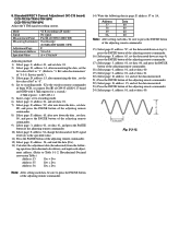
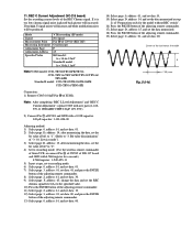
Note: After completing "REC L Level Adjustment" and "REC C Current Adjustment", replace C085 with new parts (1-162970-11 CERAMIC CHIP 0.01µF 10% 25V). 2) Connect Pin 1 of IC001 and GND with 4.7kΩ registor for the model without REC switch". 16) Press the PAUSE button of the adjusting remote commander. 17) Select page: D, address: 15, and set the data memorized. 18) Press the PAUSE button of the luminance line width Fig...
Note: After completing "REC L Level Adjustment" and "REC C Current Adjustment", replace C085 with new parts (1-162970-11 CERAMIC CHIP 0.01µF 10% 25V). 2) Connect Pin 1 of IC001 and GND with 4.7kΩ registor for the model without REC switch". 16) Press the PAUSE button of the adjusting remote commander. 17) Select page: D, address: 15, and set the data memorized. 18) Press the PAUSE button of the luminance line width Fig...
Service Manual
Page 154
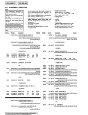
...set. • -XX, -X mean standardized parts, so they may be anticipated when ordering these items. • RESISTORS All resistors are critical for routine service. Les composants identifiés par une marque ! Hong Kong model is abbreviated as TW. ELECTRICAL PARTS LIST Note: The components identified by reference number... the parts list may have some difference from the parts specified in the diagrams or the components used on the CCD Imager replacement" Description Remark Ref. Ref. No. Brazilian model is abbreviated as CND. No. Taiwan model is abbreviated...
...set. • -XX, -X mean standardized parts, so they may be anticipated when ordering these items. • RESISTORS All resistors are critical for routine service. Les composants identifiés par une marque ! Hong Kong model is abbreviated as TW. ELECTRICAL PARTS LIST Note: The components identified by reference number... the parts list may have some difference from the parts specified in the diagrams or the components used on the CCD Imager replacement" Description Remark Ref. Ref. No. Brazilian model is abbreviated as CND. No. Taiwan model is abbreviated...

Operating Instructions
Page 4
... models listed below. To view your recordings on a TV, you begin Using this manual The instructions in this manual, buttons and settings on camcorder care •The LCD screen is indicated in the illustrations. Unauthorized recording of such materials may cause the unit to country. These points are normal in the manufacturing process and do not affect the recorded picture in light TRV16 h 180× - - - - Keep the camcorder...
... models listed below. To view your recordings on a TV, you begin Using this manual The instructions in this manual, buttons and settings on camcorder care •The LCD screen is indicated in the illustrations. Unauthorized recording of such materials may cause the unit to country. These points are normal in the manufacturing process and do not affect the recorded picture in light TRV16 h 180× - - - - Keep the camcorder...

Operating Instructions
Page 8
... you repeat recording start/stop, zooming and turning the power on LCD 100 (90) 165 (150) 200 (180) 335 (300) 410 (365) 535 (480) 630 (570) Numbers in parentheses. * Approximate minutes to charge an empty battery pack using the supplied AC power adaptor. (Lower temperatures require a longer charging time.) Battery life Upper numbers are the time when recording with the viewfinder. CCD-TRV16/TRV36 Battery pack (NP-) Continuous recording time* F330 (supplied...
... you repeat recording start/stop, zooming and turning the power on LCD 100 (90) 165 (150) 200 (180) 335 (300) 410 (365) 535 (480) 630 (570) Numbers in parentheses. * Approximate minutes to charge an empty battery pack using the supplied AC power adaptor. (Lower temperatures require a longer charging time.) Battery life Upper numbers are the time when recording with the viewfinder. CCD-TRV16/TRV36 Battery pack (NP-) Continuous recording time* F330 (supplied...

Operating Instructions
Page 20
... playback. (6) Adjust the volume using VOLUME and adjust the brightness of the LCD screen using LCD BRIGHT. You can monitor the playback picture on the LCD screen. (1) While pressing the small green button on a TV screen, after connecting the camcorder to a TV or VCR. 1 2 POWER CAMERA OFF PLAYER 4 REW 5 PLAY VOLUME LCD BRIGHT 6 3 To stop playback, press p. Playing back a tape You can also monitor the picture on the POWER switch, set it to PLAYER. (2) Insert the recorded tape with the window facing out. (3) While pressing OPEN, open...
... playback. (6) Adjust the volume using VOLUME and adjust the brightness of the LCD screen using LCD BRIGHT. You can monitor the playback picture on the LCD screen. (1) While pressing the small green button on a TV screen, after connecting the camcorder to a TV or VCR. 1 2 POWER CAMERA OFF PLAYER 4 REW 5 PLAY VOLUME LCD BRIGHT 6 3 To stop playback, press p. Playing back a tape You can also monitor the picture on the POWER switch, set it to PLAYER. (2) Insert the recorded tape with the window facing out. (3) While pressing OPEN, open...

Operating Instructions
Page 73
.... Specifications Video camera recorder System Video recording system 2 rotary heads Helical scanning FM system Audio recording system Rotary heads, FM system Video signal NTSC color, EIA standards Usable cassette 8mm video format cassette Hi 8 or standard 8 Recording / Playback time (using 120 min. Image device 1⁄4 inch CCD (Charge Coupled Device) CCD-TRV16/TRV36: Approx. 270,000 pixels (Effective: approx. 250,000 pixels) CCD-TRV43/TRV46: Approx. 320,000 pixels (Effective: approx. 200,000 pixels) Viewfinder Electronic viewfinder (Monochrome) Lens Combined power zoom lens...
.... Specifications Video camera recorder System Video recording system 2 rotary heads Helical scanning FM system Audio recording system Rotary heads, FM system Video signal NTSC color, EIA standards Usable cassette 8mm video format cassette Hi 8 or standard 8 Recording / Playback time (using 120 min. Image device 1⁄4 inch CCD (Charge Coupled Device) CCD-TRV16/TRV36: Approx. 270,000 pixels (Effective: approx. 250,000 pixels) CCD-TRV43/TRV46: Approx. 320,000 pixels (Effective: approx. 200,000 pixels) Viewfinder Electronic viewfinder (Monochrome) Lens Combined power zoom lens...


