Operating Instructions
Page 3
... complies with the instructions, may cause undesired operation. 3 Consult the dealer or an experienced radio/TV technician for a Class B digital device, pursuant to Part 15 of the following two conditions.: (1) This device may not cause harmful interference, and (2) this equipment does cause harmful interference to the following measures: - Operation ...
... complies with the instructions, may cause undesired operation. 3 Consult the dealer or an experienced radio/TV technician for a Class B digital device, pursuant to Part 15 of the following two conditions.: (1) This device may not cause harmful interference, and (2) this equipment does cause harmful interference to the following measures: - Operation ...

Operating Instructions
Page 4
... • All other countries. Memory Photo recording 77 Superimposing a still image in your camcorder 106 Focusing manually 43 Superimposing a title 44 Making your own titles 46 Inserting a scene... tape as a still image 85 Shooting backlit subjects - Dubbing a tape 57 Using with digital effects ...... 50 Enlarging recorded images - Photo save 87 Shooting in the United States and/... 32 Using the fader function 33 Using special effects - Date search 53 Identifying the parts and controls 123 Quick Function Guide 130 Index 131 Searching for a photo - Photo search...
... • All other countries. Memory Photo recording 77 Superimposing a still image in your camcorder 106 Focusing manually 43 Superimposing a title 44 Making your own titles 46 Inserting a scene... tape as a still image 85 Shooting backlit subjects - Dubbing a tape 57 Using with digital effects ...... 50 Enlarging recorded images - Photo save 87 Shooting in the United States and/... 32 Using the fader function 33 Using special effects - Date search 53 Identifying the parts and controls 123 Quick Function Guide 130 Index 131 Searching for a photo - Photo search...

Operating Instructions
Page 11
...the DC IN jack on the display window. Keep the battery pack in the display window roughly indicates the recording time with the metal parts of the DC plug of the display window is turned off. To fully charge the battery (full charge), leave the battery pack ...the AC power adaptor. Battery pack The supplied battery pack is charged a little. 11 The remaining battery time is indicated in minutes on your camcorder. Getting started Step 1 Preparing the power supply Charging the battery pack Use the battery pack after normal charge is completed until it fully discharges...
...the DC IN jack on the display window. Keep the battery pack in the display window roughly indicates the recording time with the metal parts of the DC plug of the display window is turned off. To fully charge the battery (full charge), leave the battery pack ...the AC power adaptor. Battery pack The supplied battery pack is charged a little. 11 The remaining battery time is indicated in minutes on your camcorder. Getting started Step 1 Preparing the power supply Charging the battery pack Use the battery pack after normal charge is completed until it fully discharges...

Operating Instructions
Page 15
... supply (p. 10). (2) Open the lid of indicated time on Hi8 tape. Mosaic pattern noise may not be closed when you press any part of the lid other than the mark. •Do not pick up . (4) Close the cassette compartment by holding the lid of the ... write-protect tab on the cassette to play back standard 8 tape on other camcorders (including other DCR-TRV520/TRV525). •The cassette compartment may appear when you use your camcorder by pressing the mark on this camcorder. The cassette compartment opens automatically. (3) Insert a cassette with its window facing...
... supply (p. 10). (2) Open the lid of indicated time on Hi8 tape. Mosaic pattern noise may not be closed when you press any part of the lid other than the mark. •Do not pick up . (4) Close the cassette compartment by holding the lid of the ... write-protect tab on the cassette to play back standard 8 tape on other camcorders (including other DCR-TRV520/TRV525). •The cassette compartment may appear when you use your camcorder by pressing the mark on this camcorder. The cassette compartment opens automatically. (3) Insert a cassette with its window facing...
Operating Instructions
Page 47
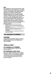
...press the dial to return To erase a character Select [C]. We recommend setting the POWER switch to VTR or removing the cassette so that your camcorder does not automatically turn it to change a title you want to CAMERA again, then proceed from step 1. To enter a space Select [Z&... ?!], then select the blank part. The characters you have stored In step 3, select CUSTOM1 or CUSTOM2, depending on which title you have entered remain stored in your camcorder The power automatically goes off while you select [ ] The menu for selecting...
...press the dial to return To erase a character Select [C]. We recommend setting the POWER switch to VTR or removing the cassette so that your camcorder does not automatically turn it to change a title you want to CAMERA again, then proceed from step 1. To enter a space Select [Z&... ?!], then select the blank part. The characters you have stored In step 3, select CUSTOM1 or CUSTOM2, depending on which title you have entered remain stored in your camcorder The power automatically goes off while you select [ ] The menu for selecting...

Operating Instructions
Page 72
...turn the power off, or detach the battery for "Memory Stick" (not supplied). "Memory Stick" operations - On file format (JPEG) Your camcorder compresses image data in the viewfinder of your personal computer. Dsc00001.jpg: This file name appears on the display of the connecting section. •...get wet. •Do not use or keep "Memory Stick"s in the following cases: - You can exchange image data with the metal parts of your camcorder. Typical image data file name 100-0001: This file name appears on the "Memory Stick" is flashing - Using "Memory Stick"-introduction You...
...turn the power off, or detach the battery for "Memory Stick" (not supplied). "Memory Stick" operations - On file format (JPEG) Your camcorder compresses image data in the viewfinder of your personal computer. Dsc00001.jpg: This file name appears on the display of the connecting section. •...get wet. •Do not use or keep "Memory Stick"s in the following cases: - You can exchange image data with the metal parts of your camcorder. Typical image data file name 100-0001: This file name appears on the "Memory Stick" is flashing - Using "Memory Stick"-introduction You...
Operating Instructions
Page 83
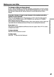
... MIX VTR "Memory Stick" operations OFF (CHARGE) MEMORY CAMERA M. MEMORY MIX Before operation Insert a Hi8 /Digital8 tape for recording and a "Memory Stick" into your camcorder. (1) Set the POWER switch to superimpose. To see the previous image, press MEMORY -. The color (bright) scheme of the area in the still image which... is superimposed on the lower part of the area in the moving image which is to be swapped with a moving image. (6) Turn the SEL/PUSH EXEC dial to adjust ...
... MIX VTR "Memory Stick" operations OFF (CHARGE) MEMORY CAMERA M. MEMORY MIX Before operation Insert a Hi8 /Digital8 tape for recording and a "Memory Stick" into your camcorder. (1) Set the POWER switch to superimpose. To see the previous image, press MEMORY -. The color (bright) scheme of the area in the still image which... is superimposed on the lower part of the area in the moving image which is to be swapped with a moving image. (6) Turn the SEL/PUSH EXEC dial to adjust ...

Operating Instructions
Page 121
...humid - Be sure to insert the batteries with the metal parts of water and then consult a doctor. Dry batteries are leaking •Wipe off with water. •If the liquid get into your eyes, wash your nearest Sony dealer. 121 Current flows from batteries when you are not ... equipment securely. •Charging while some capacity remains does not affect the original battery capacity. polarities matched to any problem occurs, unplug your camcorder and contact your eyes with a lot of the connecting section. Do not use leaking batteries. If any mechanical shock. •Do not...
...humid - Be sure to insert the batteries with the metal parts of water and then consult a doctor. Dry batteries are leaking •Wipe off with water. •If the liquid get into your eyes, wash your nearest Sony dealer. 121 Current flows from batteries when you are not ... equipment securely. •Charging while some capacity remains does not affect the original battery capacity. polarities matched to any problem occurs, unplug your camcorder and contact your eyes with a lot of the connecting section. Do not use leaking batteries. If any mechanical shock. •Do not...
Operating Instructions
Page 122
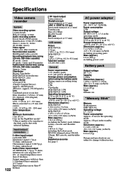
... jack Stereo minijack (ø 3.5 mm) LANC /DIGITAL I/O jack Stereo mini-minijack (ø 2.5 mm) Transfer rate: Max 115.2 Kbps RS-232C based MIC jack Stereo minijack (ø 3.5 mm) LCD screen Picture DCR-TRV520: 3.5 type 2 7/8 × 2 in. (72.2 × 50.4 mm) DCR-TRV525: 3 type 2 1/2 × 1 3/4... seen due to +60 °C) Dimensions (approx.) 5 × 1 9/16 × 2 1/2 in. (125 × 39 × 62 mm) (w/h/d) excluding projecting parts Mass (approx.) 9.8 oz (280 g) excluding power cord Battery pack Output voltage DC 7.2 V Capacity 5.0 Wh Dimensions (approx.) 1 9/16 × 13/16 × ...
... jack Stereo minijack (ø 3.5 mm) LANC /DIGITAL I/O jack Stereo mini-minijack (ø 2.5 mm) Transfer rate: Max 115.2 Kbps RS-232C based MIC jack Stereo minijack (ø 3.5 mm) LCD screen Picture DCR-TRV520: 3.5 type 2 7/8 × 2 in. (72.2 × 50.4 mm) DCR-TRV525: 3 type 2 1/2 × 1 3/4... seen due to +60 °C) Dimensions (approx.) 5 × 1 9/16 × 2 1/2 in. (125 × 39 × 62 mm) (w/h/d) excluding projecting parts Mass (approx.) 9.8 oz (280 g) excluding power cord Battery pack Output voltage DC 7.2 V Capacity 5.0 Wh Dimensions (approx.) 1 9/16 × 13/16 × ...
Operating Instructions
Page 123
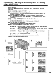
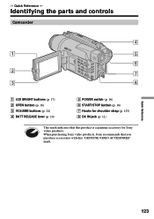
Quick Reference - Identifying the parts and controls Camcorder 4 1 5 6 2 7 3 8 1 LCD BRIGHT buttons (p. 17) 2 OPEN button (p. 16) 3 VOLUME buttons (p. 24) 4 BATT RELEASE lever (p. 10) 5 POWER switch (p. 16) 6 START/STOP button (p. 16) 7 Hooks for shoulder strap (p. 125) 8 DC IN jack (p. 11) This mark indicates that you purchase accessories with this product is a genuine accessory for Sony video products. Quick Reference 123 - When purchasing Sony video products, Sony recommends that this "GENUINE VIDEO ACCESSORIES" mark.
Quick Reference - Identifying the parts and controls Camcorder 4 1 5 6 2 7 3 8 1 LCD BRIGHT buttons (p. 17) 2 OPEN button (p. 16) 3 VOLUME buttons (p. 24) 4 BATT RELEASE lever (p. 10) 5 POWER switch (p. 16) 6 START/STOP button (p. 16) 7 Hooks for shoulder strap (p. 125) 8 DC IN jack (p. 11) This mark indicates that you purchase accessories with this product is a genuine accessory for Sony video products. Quick Reference 123 - When purchasing Sony video products, Sony recommends that this "GENUINE VIDEO ACCESSORIES" mark.

Operating Instructions
Page 124
... (playback) M FF (fastforward) X PAUSE (pause) z REC (recording) The control buttons light up when you cannot attach the tripod securely and the screw may damage your camcorder. Otherwise, you set the POWER switch to VTR. 0 EDITSEARCH buttons (p. 23) qa S.LASER LINK button (p. 28) qs Focus ring (p. 43) qd Microphone qf Camera recording...) Make sure that the length of the tripod screw is SUPER LASER LINK? wa Remote sensor What is less than 9/32 inch (6.5 mm). Identifying the parts and controls 9 0 qa qh qs qj qk qd ql qf w;
... (playback) M FF (fastforward) X PAUSE (pause) z REC (recording) The control buttons light up when you cannot attach the tripod securely and the screw may damage your camcorder. Otherwise, you set the POWER switch to VTR. 0 EDITSEARCH buttons (p. 23) qa S.LASER LINK button (p. 28) qs Focus ring (p. 43) qd Microphone qf Camera recording...) Make sure that the length of the tripod screw is SUPER LASER LINK? wa Remote sensor What is less than 9/32 inch (6.5 mm). Identifying the parts and controls 9 0 qa qh qs qj qk qd ql qf w;

Operating Instructions
Page 125
... MEMORY - button (p. 83, 89) wh LCD screen (p. 17) wj Speaker wk (self-timer) button (p. 22) wl Viewfinder lens adjustment lever (p. 19) e; Eyecup RELEASE knob (p. 119) (DCR-TRV520 only) ea MEMORY INDEX button (p. 90) es MEMORY DELETE button (p. 98) ed FADER button (p. 33) ef BACK LIGHT button (p. 20) eg PROGRAM AE button (p. 41...) eh EXPOSURE button (p. 42) ej MEMORY MIX button (p. 83) ek MEMORY + button (p. 83, 89) Attaching the shoulder strap Attach the shoulder strap supplied with your camcorder to the hooks for the shoulder strap. Quick Reference 125 Identifying the...
... MEMORY - button (p. 83, 89) wh LCD screen (p. 17) wj Speaker wk (self-timer) button (p. 22) wl Viewfinder lens adjustment lever (p. 19) e; Eyecup RELEASE knob (p. 119) (DCR-TRV520 only) ea MEMORY INDEX button (p. 90) es MEMORY DELETE button (p. 98) ed FADER button (p. 33) ef BACK LIGHT button (p. 20) eg PROGRAM AE button (p. 41...) eh EXPOSURE button (p. 42) ej MEMORY MIX button (p. 83) ek MEMORY + button (p. 83, 89) Attaching the shoulder strap Attach the shoulder strap supplied with your camcorder to the hooks for the shoulder strap. Quick Reference 125 Identifying the...
Operating Instructions
Page 126
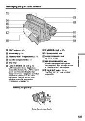
... instructions of the accessory for further information. •The intelligent accessory shoe has a safety device for fixing the installed accessory securely. Identifying the parts and controls el rg rh r; Refer to the end, and then tighten the screw. •To remove an accessory, loosen the screw, ...and then press down and pull out the accessory. 126 rj PHOTO button (p. 29, 77) rk DIGITAL EFFECT button (p. 38, 50) rl END SEARCH button (p. 23) t; PICTURE EFFECT button (p. 36, 49) ta MENU button (p. 32, 64) ts SEL/PUSH...
... instructions of the accessory for further information. •The intelligent accessory shoe has a safety device for fixing the installed accessory securely. Identifying the parts and controls el rg rh r; Refer to the end, and then tighten the screw. •To remove an accessory, loosen the screw, ...and then press down and pull out the accessory. 126 rj PHOTO button (p. 29, 77) rk DIGITAL EFFECT button (p. 38, 50) rl END SEARCH button (p. 23) t; PICTURE EFFECT button (p. 36, 49) ta MENU button (p. 32, 64) ts SEL/PUSH...
Operating Instructions
Page 127
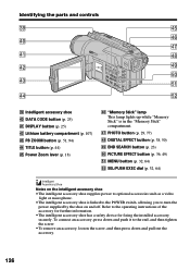
yd DV IN/OUT jack (p. 58, 86) The DV IN/OUT jack is used for Local Application Control Bus System. Identifying the parts and controls td tl tf y; tl S VIDEO ID-2 jack (p. 27) y; The LANC control jack is i.LINK compatible. This jack has the same function...yd td EJECT button (p. 15) tf Access lamp (p. 74) tg "Memory Stick" compartment (p. 74) th Cassette compartment (p. 15) tj Grip strap tk LANC /DIGITAL I/O jack (p. 91) LANC stands for controlling the tape transport of video equipment and other peripherals connected to the video equipment. i (headphones) jack ya AUDIO/VIDEO...
yd DV IN/OUT jack (p. 58, 86) The DV IN/OUT jack is used for Local Application Control Bus System. Identifying the parts and controls td tl tf y; tl S VIDEO ID-2 jack (p. 27) y; The LANC control jack is i.LINK compatible. This jack has the same function...yd td EJECT button (p. 15) tf Access lamp (p. 74) tg "Memory Stick" compartment (p. 74) th Cassette compartment (p. 15) tj Grip strap tk LANC /DIGITAL I/O jack (p. 91) LANC stands for controlling the tape transport of video equipment and other peripherals connected to the video equipment. i (headphones) jack ya AUDIO/VIDEO...
Operating Instructions
Page 128
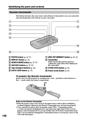
...not function properly. •Your camcorder works in the Commander mode VTR 2, we recommend changing the Commander mode or covering the sensor of the VCR with black paper. If you use another Sony VCR in the Commander mode VTR 2. Identifying the parts and controls Remote Commander The buttons... that have the same name on the Remote Commander as on your camcorder function identically to the buttons on your camcorder from strong light sources such as...
...not function properly. •Your camcorder works in the Commander mode VTR 2, we recommend changing the Commander mode or covering the sensor of the VCR with black paper. If you use another Sony VCR in the Commander mode VTR 2. Identifying the parts and controls Remote Commander The buttons... that have the same name on the Remote Commander as on your camcorder function identically to the buttons on your camcorder from strong light sources such as...

Operating Instructions
Page 129
... (p. 68) ws Warning indicators (p. 114) wd Recording lamp (p. 16) (DCR-TRV520 only) This indicator appears in the viewfinder. wg Tape counter indicator (p. 19,...indicator This indicator appears when you use the video flash light (not supplied). Identifying the parts and controls Operation indicators LCD screen and Viewfinder Display window 1 qf ws 2 2 3... battery time indicator (p. 11, 19) 4 Zoom indicator (p. 18)/Exposure indicator (p. 42) 5 Fader indicator (p. 34)/Digital effect indicator (p. 38, 50) 6 Wide mode indicator (p. 32) FRAME indicator (p. 77) 7 Picture effect indicator (p....
... (p. 68) ws Warning indicators (p. 114) wd Recording lamp (p. 16) (DCR-TRV520 only) This indicator appears in the viewfinder. wg Tape counter indicator (p. 19,...indicator This indicator appears when you use the video flash light (not supplied). Identifying the parts and controls Operation indicators LCD screen and Viewfinder Display window 1 qf ws 2 2 3... battery time indicator (p. 11, 19) 4 Zoom indicator (p. 18)/Exposure indicator (p. 42) 5 Fader indicator (p. 34)/Digital effect indicator (p. 38, 50) 6 Wide mode indicator (p. 32) FRAME indicator (p. 77) 7 Picture effect indicator (p....


