
Service Manual
Page 1
...This output is the amplifier, CD player, tape deck and tuner section in CMT-NEZ30. COMPACT DISC DECK RECEIVER 9-887-030-06 2007D05-1 © 2007.04 Sony Corporation Personal Audio Division Published by Sony Techno Create Corporation CD Section TAPE Section Model Name Using Similar Mechanism Base ...): 15 + 15 W (6 ohms at a distance of 6 to rated output. SERVICE MANUAL Ver. 1.5 2007.04 HCD-NEZ30 US Model Canadian Model UK Model E Model East European Model • HCD-NEZ30 is the value measurement at 1 kHz, 10% THD) Inputs AUDIO IN: Sensitivity 250 mV, impedance 47 kilohms Outputs ...
...This output is the amplifier, CD player, tape deck and tuner section in CMT-NEZ30. COMPACT DISC DECK RECEIVER 9-887-030-06 2007D05-1 © 2007.04 Sony Corporation Personal Audio Division Published by Sony Techno Create Corporation CD Section TAPE Section Model Name Using Similar Mechanism Base ...): 15 + 15 W (6 ohms at a distance of 6 to rated output. SERVICE MANUAL Ver. 1.5 2007.04 HCD-NEZ30 US Model Canadian Model UK Model E Model East European Model • HCD-NEZ30 is the value measurement at 1 kHz, 10% THD) Inputs AUDIO IN: Sensitivity 250 mV, impedance 47 kilohms Outputs ...

Service Manual
Page 3
...Section 40 8-6. Refer to SUPPLEMENT-3 for the CD board of printed wiring board, schematic diagram and electrical parts list of UK and East European models. Refer to SUPPLEMENT-1 for the PANEL board ... When repairing the set of except UK and East European models, refer to either of UK and East European models. HCD-NEZ30 SECTION 1 Ver. 1.5 SERVICING NOTES NOTES ON HANDLING THE ...tip has to about 40 ˚C higher than 30 cm away from the objective lens. Mechanical Deck (CMAL5Z235A 10 3-7. MAIN Section 18 7-3. MAIN Section (1/2 23 7-7. PANEL Board 26 7-9. EXPLODED ...
...Section 40 8-6. Refer to SUPPLEMENT-3 for the CD board of printed wiring board, schematic diagram and electrical parts list of UK and East European models. Refer to SUPPLEMENT-1 for the PANEL board ... When repairing the set of except UK and East European models, refer to either of UK and East European models. HCD-NEZ30 SECTION 1 Ver. 1.5 SERVICING NOTES NOTES ON HANDLING THE ...tip has to about 40 ˚C higher than 30 cm away from the objective lens. Mechanical Deck (CMAL5Z235A 10 3-7. MAIN Section 18 7-3. MAIN Section (1/2 23 7-7. PANEL Board 26 7-9. EXPLODED ...

Service Manual
Page 4
... with inward motion for the focus search. of DC board have been changed along with it may be bent or damaged. 3. HCD-NEZ30 Ver. 1.5 LASER DIODE AND FOCUS SEARCH OPERATION CHECK During normal operation of the equipment, emission of the laser diode is prohibited ... 4.7K 5% 1/10W 1-216-845-11 METAL CHIP 100K 5% 1/10W 1-216-864-11 SHORT CHIP 0 A-1216-850-A Model Name E model Mexican model Chilean and Peruvian models Argentina model US and Canadian models UK model East European model Part No. 2-665-907-0[] 2-665-908-0[] 2-665-909-0[] 2-665-910-0[] 2-665-913-0[] 3-100-772-0[] 3-312-856...
... with inward motion for the focus search. of DC board have been changed along with it may be bent or damaged. 3. HCD-NEZ30 Ver. 1.5 LASER DIODE AND FOCUS SEARCH OPERATION CHECK During normal operation of the equipment, emission of the laser diode is prohibited ... 4.7K 5% 1/10W 1-216-845-11 METAL CHIP 100K 5% 1/10W 1-216-864-11 SHORT CHIP 0 A-1216-850-A Model Name E model Mexican model Chilean and Peruvian models Argentina model US and Canadian models UK model East European model Part No. 2-665-907-0[] 2-665-908-0[] 2-665-909-0[] 2-665-910-0[] 2-665-913-0[] 3-100-772-0[] 3-312-856...

Service Manual
Page 6
HCD-NEZ30 Ver. 1.1 ...tape deck. Tape TAPE on the remote. Press (play) on the remote (or CD/ pause) on the unit). (play /pause) on the unit again to close the CD compartment,...go back/go forward) . Press PUSH OPEN/CLOSE on the unit). total playing time for the North American model Before using an audio cord) until "AUTO" appears. 3 Tune in the folder on the remote. 2 ... time for an MP3 disc. - To connect an optional component Connect additional audio component to the PHONES jack on the CD compartment. Tuner TUNER/BAND . MP3 files is 150...
HCD-NEZ30 Ver. 1.1 ...tape deck. Tape TAPE on the remote. Press (play) on the remote (or CD/ pause) on the unit). (play /pause) on the unit again to close the CD compartment,...go back/go forward) . Press PUSH OPEN/CLOSE on the unit). total playing time for the North American model Before using an audio cord) until "AUTO" appears. 3 Tune in the folder on the remote. 2 ... time for an MP3 disc. - To connect an optional component Connect additional audio component to the PHONES jack on the CD compartment. Tuner TUNER/BAND . MP3 files is 150...

Service Manual
Page 12
...the liquid crystal display. The message "9K STEP" or "10K STEP" is displayed on the liquid crystal display, and thus the channel step is . HCD-NEZ30 Ver. 1.5 SECTION 4 TEST MODE COLD RESET The cold reset clears all segments of liquid crystal display are turned on. 3. Press the [DSGX] button,...this case, released of the micro computer are displayed. Each time a key is pressed, the numerical value corresponding to CD. 2. TUNER STEP CHANGE-OVER (Except UK and East European models) Either the 9 kHz step or 10 kHz step can be selected for specified time Tracking not turned ON Blank ...
...the liquid crystal display. The message "9K STEP" or "10K STEP" is displayed on the liquid crystal display, and thus the channel step is . HCD-NEZ30 Ver. 1.5 SECTION 4 TEST MODE COLD RESET The cold reset clears all segments of liquid crystal display are turned on. 3. Press the [DSGX] button,...this case, released of the micro computer are displayed. Each time a key is pressed, the numerical value corresponding to CD. 2. TUNER STEP CHANGE-OVER (Except UK and East European models) Either the 9 kHz step or 10 kHz step can be selected for specified time Tracking not turned ON Blank ...

Service Manual
Page 18
...DC DETECT Q318 - 320 DO DI CLK CE TUNED M TAPE MECHANISM DECK BLOCK MOTOR 10V (CAPSTAN/REEL) SOL 10V (DECK-A) PACK REC END SW CAPSTAN/REEL MOTOR DRIVE Q804, 805 PLUNGER DRIVE... Peruvian models RECT D911 - 914 RECT D907 - 910 D922, 923 (EXCEPT E, E51) SUB POWER TRANSFORMER T901 (E, E51) VOLTAGE SELECTOR S901 RY901 (AC IN) (EXCEPT E, E51) MAIN POWER RELAY DRIVE Q315 HCD-NEZ30 18 18...SYSTEM CONTROLLER IC801 (2/2) S820 (CD LID OPEN/CLOSE DETECT) 28 I-SW_CD-LID VOLUME ROTARY ENCODER RV801 48 I-RE-VOL 63, 64, 67 - 89, 94 - 100, 1 59 - 62 REMOTE CONTROL RECEIVER IC802 9 I-RMC (SIRCS)...
...DC DETECT Q318 - 320 DO DI CLK CE TUNED M TAPE MECHANISM DECK BLOCK MOTOR 10V (CAPSTAN/REEL) SOL 10V (DECK-A) PACK REC END SW CAPSTAN/REEL MOTOR DRIVE Q804, 805 PLUNGER DRIVE... Peruvian models RECT D911 - 914 RECT D907 - 910 D922, 923 (EXCEPT E, E51) SUB POWER TRANSFORMER T901 (E, E51) VOLTAGE SELECTOR S901 RY901 (AC IN) (EXCEPT E, E51) MAIN POWER RELAY DRIVE Q315 HCD-NEZ30 18 18...SYSTEM CONTROLLER IC801 (2/2) S820 (CD LID OPEN/CLOSE DETECT) 28 I-SW_CD-LID VOLUME ROTARY ENCODER RV801 48 I-RE-VOL 63, 64, 67 - 89, 94 - 100, 1 59 - 62 REMOTE CONTROL RECEIVER IC802 9 I-RMC (SIRCS)...

Service Manual
Page 19
... : East European model MX : Mexican model • Circuit Boards Location PANEL board DC board HCD-NEZ30 Ver. 1.5 CONNECT board AC board CD board MAIN board SHIELD board (EXCEPT UK, East European) HEAD PHONE board TUNER UNIT HCD-NEZ30 19 19 Parts on the parts face side seen from the pattern face are omitted. Note: The components identified by...
... : East European model MX : Mexican model • Circuit Boards Location PANEL board DC board HCD-NEZ30 Ver. 1.5 CONNECT board AC board CD board MAIN board SHIELD board (EXCEPT UK, East European) HEAD PHONE board TUNER UNIT HCD-NEZ30 19 19 Parts on the parts face side seen from the pattern face are omitted. Note: The components identified by...

Service Manual
Page 20
PRINTED WIRING BOARD - HCD-NEZ30 Ver. 1.5 7-3. When repairing the set . CD Board - • See page 19 for Circuit Boards Location. : Uses unleaded solder. 1 2 3 4 5 6 7 8 9 10 A CD BOARD (COMPONENT SIDE) C401 B C R401 D C201 R201 E C202 C424 C101 C102 C108 C110 R207 R202 C203 R423 C406 R421 C272 C104 C109... OPTICAL PICK-UP BLOCK KSM-213CDP 11 1-868-067- (11) Refer to the set of except UK and East European models, refer to either of original service manual/SUPPLEMENT-1 according to SUPPLEMENT-1 for the CD board of printed wiring board of UK and East European...
PRINTED WIRING BOARD - HCD-NEZ30 Ver. 1.5 7-3. When repairing the set . CD Board - • See page 19 for Circuit Boards Location. : Uses unleaded solder. 1 2 3 4 5 6 7 8 9 10 A CD BOARD (COMPONENT SIDE) C401 B C R401 D C201 R201 E C202 C424 C101 C102 C108 C110 R207 R202 C203 R423 C406 R421 C272 C104 C109... OPTICAL PICK-UP BLOCK KSM-213CDP 11 1-868-067- (11) Refer to the set of except UK and East European models, refer to either of original service manual/SUPPLEMENT-1 according to SUPPLEMENT-1 for the CD board of printed wiring board of UK and East European...

Service Manual
Page 21
... POWVCC MUTE GND C405 0.1 SPSP+ SLSL+ C406 0.1 S201 (LIMIT) OPTICAL PICK-UP BLOCK KSM-213CDP M401 (SPINDLE) M402 (SLED) HCD-NEZ30 Refer to SUPPLEMENT-1 for IC Pin Function Description. CD Board - • See page 25 for Waveforms. • See page 25 for IC Block Diagrams. • See page 31 for ...the CD board of schematic diagram of original service manual/SUPPLEMENT-1 according to the set of except UK and East European models, refer to either of UK and East European models. When repairing the set . 21 21 R451 22k TP2 R452 ...
... POWVCC MUTE GND C405 0.1 SPSP+ SLSL+ C406 0.1 S201 (LIMIT) OPTICAL PICK-UP BLOCK KSM-213CDP M401 (SPINDLE) M402 (SLED) HCD-NEZ30 Refer to SUPPLEMENT-1 for IC Pin Function Description. CD Board - • See page 25 for Waveforms. • See page 25 for IC Block Diagrams. • See page 31 for ...the CD board of schematic diagram of original service manual/SUPPLEMENT-1 according to the set of except UK and East European models, refer to either of UK and East European models. When repairing the set . 21 21 R451 22k TP2 R452 ...

Service Manual
Page 22
... 8 9 10 11 12 13 14 15 MAIN BOARD A (Page 26) D PANEL BOARD (Page 20) A CD BOARD CN102 (Page 28) B DC BOARD CN903 C354 Q344 R312 C367 R138 E C217 R226 C221 R225 R125 R304 JW147...D-4 D-5 E-10 E-10 A-4 B-2 B-3 Refer to the set of US and Canadian models, refer to either of UK and East European models. PRINTED WIRING BOARDS - R C233 JW216 C357 Q319 R539 R229 F PANEL BOARD (Page...11 1-869-180- (11) • Semiconductor Location Ref. Location Ref. Location Ref. HCD-NEZ30 When repairing the set . J302 SPEAKER JW215 (REC/PB/ERASE) R245 R232 R235 JW157 ...
... 8 9 10 11 12 13 14 15 MAIN BOARD A (Page 26) D PANEL BOARD (Page 20) A CD BOARD CN102 (Page 28) B DC BOARD CN903 C354 Q344 R312 C367 R138 E C217 R226 C221 R225 R125 R304 JW147...D-4 D-5 E-10 E-10 A-4 B-2 B-3 Refer to the set of US and Canadian models, refer to either of UK and East European models. PRINTED WIRING BOARDS - R C233 JW216 C357 Q319 R539 R229 F PANEL BOARD (Page...11 1-869-180- (11) • Semiconductor Location Ref. Location Ref. Location Ref. HCD-NEZ30 When repairing the set . J302 SPEAKER JW215 (REC/PB/ERASE) R245 R232 R235 JW157 ...

Service Manual
Page 23
SCHEMATIC DIAGRAM - HCD-NEZ30 Ver. 1.1 (Page 24) A1 A2 A4 A5 A6 A7 A8 J321 AUDIO IN R236 10k C226 220p ...R385 1k R386 100 R391 R392 D324 UDZSTE-174.7B D320 MC2840-T112-1 R521 10k R517 47k D307 1SS355TE CD-R C238 22 50V CD-L C138 22 50V SCOR SENS XLAT MP3-ACK MP3-O-REQ MP3-XLAT MP3-DATA CLK MP3-I-REQ XRST ...HPGND SP-L SP-L SP-L HP-L HP-L HP-L CN500 13P (Page 24) (Page 24) HCD-NEZ30 23 23 Refer to the set. When repairing the set of US and Canadian models, refer to either of original service manual/SUPPLEMENT-1 according to SUPPLEMENT-1 for the MAIN board of ...
SCHEMATIC DIAGRAM - HCD-NEZ30 Ver. 1.1 (Page 24) A1 A2 A4 A5 A6 A7 A8 J321 AUDIO IN R236 10k C226 220p ...R385 1k R386 100 R391 R392 D324 UDZSTE-174.7B D320 MC2840-T112-1 R521 10k R517 47k D307 1SS355TE CD-R C238 22 50V CD-L C138 22 50V SCOR SENS XLAT MP3-ACK MP3-O-REQ MP3-XLAT MP3-DATA CLK MP3-I-REQ XRST ...HPGND SP-L SP-L SP-L HP-L HP-L HP-L CN500 13P (Page 24) (Page 24) HCD-NEZ30 23 23 Refer to the set. When repairing the set of US and Canadian models, refer to either of original service manual/SUPPLEMENT-1 according to SUPPLEMENT-1 for the MAIN board of ...

Service Manual
Page 24
.../SUPPLEMENT-1 according to the set . When repairing the set of except UK and East European models, refer to either of original service manual/ SUPPLEMENT-2 according to the set . 24 HCD-NEZ30 24 Refer to SUPPLEMENT-1 for the HEAD PHONE board of schematic diagram of except US and ...Canadian models. SCHEMATIC DIAGRAM - HCD-NEZ30 Ver. 1.5 7-7. MAIN Section (2/2) - • See page 25 for Waveforms. • See page 25 for IC Block Diagrams. FM 75Ω COAXIAL ANTENNA AM (2/2) R135 100k R235 100k C235 10 50V C135 10 50V CD-L CD-R R226 0 R126 0 R125 22k...
.../SUPPLEMENT-1 according to the set . When repairing the set of except UK and East European models, refer to either of original service manual/ SUPPLEMENT-2 according to the set . 24 HCD-NEZ30 24 Refer to SUPPLEMENT-1 for the HEAD PHONE board of schematic diagram of except US and ...Canadian models. SCHEMATIC DIAGRAM - HCD-NEZ30 Ver. 1.5 7-7. MAIN Section (2/2) - • See page 25 for Waveforms. • See page 25 for IC Block Diagrams. FM 75Ω COAXIAL ANTENNA AM (2/2) R135 100k R235 100k C235 10 50V C135 10 50V CD-L CD-R R226 0 R126 0 R125 22k...

Service Manual
Page 26
... R824 R825 R826 LCD801 LIQUID CRYSTAL DISPLAY JW896 JW895 100 81 50 S820 CD LID C OPEN/CLOSE DETECT 17 1 CN804 2 1 (EXCEPT US, CND) S807 + R877 JW828 - TAPE MECHANISM DECK BLOCK SUPPLIED WITH THE ASSEMBLED BLOCK 26 26 S806 R725 R710 R702 R701...8226; See page 19 for the PANEL board of printed wiring board of original service manual/SUPPLEMENT-3 according to either of UK and East European models. HCD-NEZ30 Ver. 1.5 • Semiconductor Location Ref. Location D801 G-7 D804 C-4 D805 C-4 D806 F-8 D807 C-9 D809 D-9 IC801 D-7 IC802 E-9 IC803 D-9 Q801 C-8...
... R824 R825 R826 LCD801 LIQUID CRYSTAL DISPLAY JW896 JW895 100 81 50 S820 CD LID C OPEN/CLOSE DETECT 17 1 CN804 2 1 (EXCEPT US, CND) S807 + R877 JW828 - TAPE MECHANISM DECK BLOCK SUPPLIED WITH THE ASSEMBLED BLOCK 26 26 S806 R725 R710 R702 R701...8226; See page 19 for the PANEL board of printed wiring board of original service manual/SUPPLEMENT-3 according to either of UK and East European models. HCD-NEZ30 Ver. 1.5 • Semiconductor Location Ref. Location D801 G-7 D804 C-4 D805 C-4 D806 F-8 D807 C-9 D809 D-9 IC801 D-7 IC802 E-9 IC803 D-9 Q801 C-8...

Service Manual
Page 27
...3V(MAIN) D-GND D+4V(SUB) D-GND ACDET POWER-ON I-PWR.MONI M-GND M+10V 1 TAPE MECHANISM DECK BLOCK SUPPLIED WITH THE ASSEMBLED BLOCK 1 REC PACK MOTOR10V R849 4.7k SOL10V COM GND END SW 6 FFC801 ...NJL23H400A Q808 2SC3052EF-T1-LEF V GO C811 10 16V 9 C812 470p R815 1k REMOTE CONTROL RECEIVER R805 0 R863 100 R841 1k D806 SLR342 STANDBY O-LED-STBY R842 10k C803 0.01 ...2 FFC804 (Page 24) (NC) S820 CD LID OPEN/CLOSE DETECT HCD-NEZ30 Refer to the set of except UK and East European models, refer to either of UK and East European models. S813 TUNING + S805 PLAY MODE/ TUNING...
...3V(MAIN) D-GND D+4V(SUB) D-GND ACDET POWER-ON I-PWR.MONI M-GND M+10V 1 TAPE MECHANISM DECK BLOCK SUPPLIED WITH THE ASSEMBLED BLOCK 1 REC PACK MOTOR10V R849 4.7k SOL10V COM GND END SW 6 FFC801 ...NJL23H400A Q808 2SC3052EF-T1-LEF V GO C811 10 16V 9 C812 470p R815 1k REMOTE CONTROL RECEIVER R805 0 R863 100 R841 1k D806 SLR342 STANDBY O-LED-STBY R842 10k C803 0.01 ...2 FFC804 (Page 24) (NC) S820 CD LID OPEN/CLOSE DETECT HCD-NEZ30 Refer to the set of except UK and East European models, refer to either of UK and East European models. S813 TUNING + S805 PLAY MODE/ TUNING...

Service Manual
Page 28
...JW915 C919 D930 C918 JW942 JW914 JW960 C923 IC901 JW951 JW939 JW925 G C336 C350 1 3 JW846 R916 E Q333 KK D322 E Q338 A R915 R914 H HCD-NEZ30 Note: Refer to "NOTE WHEN PARTS RELATED TO POWER TRANSFORMER ARE REPLACED" (page 4) in the servicing notes when the entire DC board, D921, R911,... R912, or R920 is replaced. (US and Canadian models only) 28 28 JW931 8 9 10 11 (US, CND) (Page 29) J AC BOARD 1 1 2 2 3 3 4 (EXCEPT US, CND) (Page 29) P AC BOARD 4 5 5 ...
...JW915 C919 D930 C918 JW942 JW914 JW960 C923 IC901 JW951 JW939 JW925 G C336 C350 1 3 JW846 R916 E Q333 KK D322 E Q338 A R915 R914 H HCD-NEZ30 Note: Refer to "NOTE WHEN PARTS RELATED TO POWER TRANSFORMER ARE REPLACED" (page 4) in the servicing notes when the entire DC board, D921, R911,... R912, or R920 is replaced. (US and Canadian models only) 28 28 JW931 8 9 10 11 (US, CND) (Page 29) J AC BOARD 1 1 2 2 3 3 4 (EXCEPT US, CND) (Page 29) P AC BOARD 4 5 5 ...

Service Manual
Page 29
... 7 8 9 10 11 AC BOARD A B C D E (EXCEPT E, E51) (E, E51) JW917 C931 F JW918 JW906 LF901 (EXCEPT E, E51) G (AC IN) H CN901 1 2 (US, CND) R903 WIRE900 (CHASSIS) HCD-NEZ30 JW907 JW908 JW905 JW901 JW929 JW919 D906 RY901 S901 VOLTAGE SELECTOR 230 - 240V t 220V t120V (E, E51) (EXCEPT E, E51) JW904 (E, E51) (US, CND, E, E51, MX) (UK, ...TRANSFORMER ARE REPLACED" (page 4) in the servicing notes when the T901 or T902 is replaced. (US and Canadian models only) 29 29 No. AC Board - • See page 19 for Circuit Boards Location. : Uses unleaded solder. 7-11.
... 7 8 9 10 11 AC BOARD A B C D E (EXCEPT E, E51) (E, E51) JW917 C931 F JW918 JW906 LF901 (EXCEPT E, E51) G (AC IN) H CN901 1 2 (US, CND) R903 WIRE900 (CHASSIS) HCD-NEZ30 JW907 JW908 JW905 JW901 JW929 JW919 D906 RY901 S901 VOLTAGE SELECTOR 230 - 240V t 220V t120V (E, E51) (EXCEPT E, E51) JW904 (E, E51) (US, CND, E, E51, MX) (UK, ...TRANSFORMER ARE REPLACED" (page 4) in the servicing notes when the T901 or T902 is replaced. (US and Canadian models only) 29 29 No. AC Board - • See page 19 for Circuit Boards Location. : Uses unleaded solder. 7-11.

Service Manual
Page 30
HCD-NEZ30 Ver. 1.5 7-12. SCHEMATIC DIAGRAM - POWER SUPPLY Section - (Page 23) (Page 27) (Page 23) CN903 4P +4V REGULATOR +B GND -B GND(CT) CN900 9P D+3.3V(MAIN) DGND D+... TRANSFORMER ARE REPLACED" (page 4) in the servicing notes when the entire DC board, D921, R911, R912, R920, T901 or T902 is replaced. (US and Canadian models only) HCD-NEZ30 30 30
HCD-NEZ30 Ver. 1.5 7-12. SCHEMATIC DIAGRAM - POWER SUPPLY Section - (Page 23) (Page 27) (Page 23) CN903 4P +4V REGULATOR +B GND -B GND(CT) CN900 9P D+3.3V(MAIN) DGND D+... TRANSFORMER ARE REPLACED" (page 4) in the servicing notes when the entire DC board, D921, R911, R912, R920, T901 or T902 is replaced. (US and Canadian models only) HCD-NEZ30 30 30
Service Manual
Page 35
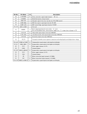
...display 90 VCC - Terminal for VOLUME control) I MP3 data request signal input from the CD DSP I MP3 acknowledge signal input from the reset switch "L": reset For several hundreds msec. Power supply terminal (+3.2V) 91 VSS - HCD-NEZ30 Pin No. 46 47 48 49 50 51 to 53 Pin Name O-POWER I-SUFFIX I-RE...-VOL I-MP3-REQ I-MP3-ACK MD2 to MD0 54 RESET 55 O-TU-CE 56 O-TU-CLK 57 O-TU-DI I/O Description O Power relay drive signal output terminal "H": on I Model destination setting terminal I Dial...
...display 90 VCC - Terminal for VOLUME control) I MP3 data request signal input from the CD DSP I MP3 acknowledge signal input from the reset switch "L": reset For several hundreds msec. Power supply terminal (+3.2V) 91 VSS - HCD-NEZ30 Pin No. 46 47 48 49 50 51 to 53 Pin Name O-POWER I-SUFFIX I-RE...-VOL I-MP3-REQ I-MP3-ACK MD2 to MD0 54 RESET 55 O-TU-CE 56 O-TU-CLK 57 O-TU-DI I/O Description O Power relay drive signal output terminal "H": on I Model destination setting terminal I Dial...

Service Manual
Page 36
...supplied #2 #2 2 mechanical deck section not supplied 2 #4 1 not supplied #1 (WIRE300) #1 3 1 not supplied MAIN board section Ref. Replace only with mark 0 are critical for routine service. HCD-NEZ30 Ver. 1.5 SECTION 8 ...EXPLODED VIEWS NOTE: • -XX and -X mean standardized parts, so they • Items marked "*" are not stocked since they may have some difference from the original are given in the exploded views are not supplied. • Accessories are seldom required for safety. CABINET SECTION The components...
...supplied #2 #2 2 mechanical deck section not supplied 2 #4 1 not supplied #1 (WIRE300) #1 3 1 not supplied MAIN board section Ref. Replace only with mark 0 are critical for routine service. HCD-NEZ30 Ver. 1.5 SECTION 8 ...EXPLODED VIEWS NOTE: • -XX and -X mean standardized parts, so they • Items marked "*" are not stocked since they may have some difference from the original are given in the exploded views are not supplied. • Accessories are seldom required for safety. CABINET SECTION The components...

Service Manual
Page 41
8-6. AC BOARD, DC BOARD SECTION HCD-NEZ30 Ver. 1.5 DC board 251 #1 252 not supplied (CONNECT board) 254 255 T902 256 Note: Refer to "NOTE WHEN PARTS RELATED TO POWER TRANSFORMER ARE REPLACED" (page 4) in the servicing notes when the complete DC board or T902 is replaced. (US and Canadian models only) Ref. No. 255...
8-6. AC BOARD, DC BOARD SECTION HCD-NEZ30 Ver. 1.5 DC board 251 #1 252 not supplied (CONNECT board) 254 255 T902 256 Note: Refer to "NOTE WHEN PARTS RELATED TO POWER TRANSFORMER ARE REPLACED" (page 4) in the servicing notes when the complete DC board or T902 is replaced. (US and Canadian models only) Ref. No. 255...


