
Operating Instructions
Page 6
...Blu-ray Disc/DVD 62 (One-Touch Play) Enjoying the TV sound from the speakers 62 (System Audio Control) Turning off the TV, system, and connected components 64 (System Power Off) Enjoying the components while the system is in standby mode 65 (HDMI Pass Through) Tuner Functions Listening to FM/AM...radio using the front panel display of the subwoofer ....... 68 Advanced Settings Controlling connected Sony components with the remote 72 Changing the input button assignments of the remote 75 Setting the speaker level 78 Adjusting the delay between the sound and the image 79 (A/V Sync) Enjoying...
...Blu-ray Disc/DVD 62 (One-Touch Play) Enjoying the TV sound from the speakers 62 (System Audio Control) Turning off the TV, system, and connected components 64 (System Power Off) Enjoying the components while the system is in standby mode 65 (HDMI Pass Through) Tuner Functions Listening to FM/AM...radio using the front panel display of the subwoofer ....... 68 Advanced Settings Controlling connected Sony components with the remote 72 Changing the input button assignments of the remote 75 Setting the speaker level 78 Adjusting the delay between the sound and the image 79 (A/V Sync) Enjoying...

Operating Instructions
Page 8
...; Subwoofer (SA-WCT500) (1) • Remote commander (RMANP037) (1) • Screws for the extension bracket (large, +PSW5 × 12 mm) (7) • Speaker (SS-CT500) (1) • Screws for the rear cover (small, M3 × 8 mm) (4) • AM loop antenna (aerial) (1) • R6...8226; FM wire antenna (aerial) (1) • WS-CT500EB • Extension bracket (1) • Screw for the support belt (+PSW4 × 20 mm) (1) • Speaker cord (1) • Rear cover (1) • Digital optical cord for a TV • Clamper (1) (2.5 m) (1) • Wood screw for the support belt (M3.8 &#...
...; Subwoofer (SA-WCT500) (1) • Remote commander (RMANP037) (1) • Screws for the extension bracket (large, +PSW5 × 12 mm) (7) • Speaker (SS-CT500) (1) • Screws for the rear cover (small, M3 × 8 mm) (4) • AM loop antenna (aerial) (1) • R6...8226; FM wire antenna (aerial) (1) • WS-CT500EB • Extension bracket (1) • Screw for the support belt (+PSW4 × 20 mm) (1) • Speaker cord (1) • Rear cover (1) • Digital optical cord for a TV • Clamper (1) (2.5 m) (1) • Wood screw for the support belt (M3.8 &#...

Operating Instructions
Page 9
... one. • Do not drop any foreign object into the remote Insert two R6 (size AA) batteries (supplied) by matching the 3 and # ends on the speaker or in the front panel display of time, remove the batteries to use the remote, point it at the remote sensor on the batteries to...
... one. • Do not drop any foreign object into the remote Insert two R6 (size AA) batteries (supplied) by matching the 3 and # ends on the speaker or in the front panel display of time, remove the batteries to use the remote, point it at the remote sensor on the batteries to...

Operating Instructions
Page 10
Install the speaker on a wall" (page 24). For details, see "Installing the speaker on a rack. Step 1: Positioning the system The illustrations below are examples of the subwoofer. 10US For details, see "Hanging the speaker and TV on the rear panel of the subwoofer. • Do not cover the grill of how to install the subwoofer and speaker. Notes • Do not block the heat ventilation on a wall" (page 21). You can install the speaker on the TV stand or hang the speaker on the TV stand" (page 15). For details, see "Installing the speaker on a wall.
Install the speaker on a wall" (page 24). For details, see "Installing the speaker on a rack. Step 1: Positioning the system The illustrations below are examples of the subwoofer. 10US For details, see "Hanging the speaker and TV on the rear panel of the subwoofer. • Do not cover the grill of how to install the subwoofer and speaker. Notes • Do not block the heat ventilation on a wall" (page 21). You can install the speaker on the TV stand or hang the speaker on the TV stand" (page 15). For details, see "Installing the speaker on a wall.

Operating Instructions
Page 11
Rear of the speaker REMOTE R CENTER L CTRL ONLY FOR SA-WCT500 Connector for the remote control to the speaker. 11US Getting Started Connecting the speaker cord to match the color of the SPEAKER jacks. Connect the connector for the remote control A A Speaker cord (supplied) White Green Red Note • When you install the speaker or a TV on the type of speaker. Connect the speaker cords to the speaker The connector of the speaker cords and the color tube are color-coded depending on a wall, be careful not to stumble over the cord connected to the REMOTE CTRL jack.
Rear of the speaker REMOTE R CENTER L CTRL ONLY FOR SA-WCT500 Connector for the remote control to the speaker. 11US Getting Started Connecting the speaker cord to match the color of the SPEAKER jacks. Connect the connector for the remote control A A Speaker cord (supplied) White Green Red Note • When you install the speaker or a TV on the type of speaker. Connect the speaker cords to the speaker The connector of the speaker cords and the color tube are color-coded depending on a wall, be careful not to stumble over the cord connected to the REMOTE CTRL jack.
Operating Instructions
Page 12
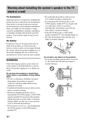
Your statutory rights (if any damages or injury caused by Sony are designed with excessive force during cleaning or maintenance. • If you do so, the system may fall and cause injury or property damage. • If the SS-CT500 speaker or SS-CT500 speaker-installed TV is not liable for any ) are not ... SS-CT500 speakerinstalled TV. • Do not handle the products with safety in mind. Warning about installing the system's speaker to the TV stand or a wall To Customers Sufficient expertise is a possibility of them where there is required for installing this product. Do not ...
Your statutory rights (if any damages or injury caused by Sony are designed with excessive force during cleaning or maintenance. • If you do so, the system may fall and cause injury or property damage. • If the SS-CT500 speaker or SS-CT500 speaker-installed TV is not liable for any ) are not ... SS-CT500 speakerinstalled TV. • Do not handle the products with safety in mind. Warning about installing the system's speaker to the TV stand or a wall To Customers Sufficient expertise is a possibility of them where there is required for installing this product. Do not ...

Operating Instructions
Page 14
..., do not hold it by the SS-CT500 speaker part. If you install equipment other than that two or more persons carry the SS- Be sure to secure the system's speaker and TV. • Secure the SS-CT500 speaker and TV firmly when installing them to the speaker or TV with hard objects, such as... a screwdriver, etc. If the SS-CT500 speaker and TV are designed for a long time, the wall behind or...
..., do not hold it by the SS-CT500 speaker part. If you install equipment other than that two or more persons carry the SS- Be sure to secure the system's speaker and TV. • Secure the SS-CT500 speaker and TV firmly when installing them to the speaker or TV with hard objects, such as... a screwdriver, etc. If the SS-CT500 speaker and TV are designed for a long time, the wall behind or...

Operating Instructions
Page 15
Getting Started Installing the speaker on the TV stand following TV models (not supplied): • KDL-40/46XBR9 • KDL-40/46W51xx* * In the actual model names, the "xx" indicates ... procedure. 1 Remove the screws of the LCD. Although the shape of the TV stand base differs depending on the TV model, you can install the speaker on the TV stand You can install the speaker with the screen side down to each model. continued 15US
Getting Started Installing the speaker on the TV stand following TV models (not supplied): • KDL-40/46XBR9 • KDL-40/46W51xx* * In the actual model names, the "xx" indicates ... procedure. 1 Remove the screws of the LCD. Although the shape of the TV stand base differs depending on the TV model, you can install the speaker on the TV stand You can install the speaker with the screen side down to each model. continued 15US
Operating Instructions
Page 17
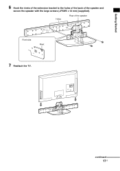
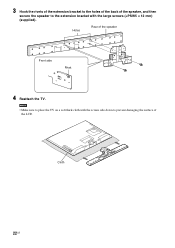
Getting Started 6 Hook the rivets of the extension bracket to the holes of the back of the speaker Front side Rivet 7 Reattach the TV. continued 17US Holes Rear of the speaker and secure the speaker with the large screws (+PSW5 × 12 mm) (supplied).
Getting Started 6 Hook the rivets of the extension bracket to the holes of the back of the speaker Front side Rivet 7 Reattach the TV. continued 17US Holes Rear of the speaker and secure the speaker with the large screws (+PSW5 × 12 mm) (supplied).

Operating Instructions
Page 18
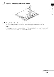
Rear cover 18US Note • When carrying the SS-CT500 speaker-installed TV, do not hold it by the SS-CT500 speaker part. Doing so may cause damage or injury. 8 Secure the TV with the screws removed in step 1. 9 Attach the rear cover (supplied) with the small screws (M3 × 8 mm) (supplied).
Rear cover 18US Note • When carrying the SS-CT500 speaker-installed TV, do not hold it by the SS-CT500 speaker part. Doing so may cause damage or injury. 8 Secure the TV with the screws removed in step 1. 9 Attach the rear cover (supplied) with the small screws (M3 × 8 mm) (supplied).
Operating Instructions
Page 21
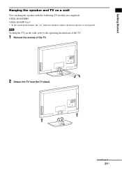
Getting Started Hanging the speaker and TV on the wall, refer to each model. Note To hang the TV on a wall You can hang the speaker with the following TV models (not supplied): • KDL-40/46XBR9 • KDL-40/46W51xx* * In the actual model names, the "xx" indicates numbers and/or characters specific to the operating instructions of the TV. 1 Remove the screws of the TV. 2 Detach the TV from the TV stand. continued 21US
Getting Started Hanging the speaker and TV on the wall, refer to each model. Note To hang the TV on a wall You can hang the speaker with the following TV models (not supplied): • KDL-40/46XBR9 • KDL-40/46W51xx* * In the actual model names, the "xx" indicates numbers and/or characters specific to the operating instructions of the TV. 1 Remove the screws of the TV. 2 Detach the TV from the TV stand. continued 21US
Operating Instructions
Page 22
Holes Rear of the speaker Front side Rivet 4 Reattach the TV. Cloth 22US Note • Make sure to prevent damaging the surface of the LCD. 3 Hook the rivets of the extension bracket to the holes of the back of the speaker, and then secure the speaker to the extension bracket with the screen side down to place the TV on a soft thick cloth with the large screws (+PSW5 × 12 mm) (supplied).
Holes Rear of the speaker Front side Rivet 4 Reattach the TV. Cloth 22US Note • Make sure to prevent damaging the surface of the LCD. 3 Hook the rivets of the extension bracket to the holes of the back of the speaker, and then secure the speaker to the extension bracket with the screen side down to place the TV on a soft thick cloth with the large screws (+PSW5 × 12 mm) (supplied).
Operating Instructions
Page 23
Doing so may cause damage or injury. Getting Started 5 Secure the TV with the screws removed in step 1. 6 Hang the TV on the wall, refer to the operating instructions of the TV. For details on hanging the TV on the wall. continued 23US Note • When hanging the SS-CT500 speaker-installed TV on the wall or taking it off the wall, do not hold it by the SS-CT500 speaker part.
Doing so may cause damage or injury. Getting Started 5 Secure the TV with the screws removed in step 1. 6 Hang the TV on the wall, refer to the operating instructions of the TV. For details on hanging the TV on the wall. continued 23US Note • When hanging the SS-CT500 speaker-installed TV on the wall or taking it off the wall, do not hold it by the SS-CT500 speaker part.
Operating Instructions
Page 24
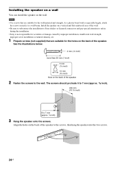
... and pay special attention to safety during the installation. • Sony is especially fragile, attach the screws securely to the screws, then hang the speaker onto the two screws. 24US Installing the speaker on a wall You can install the speaker on the back of the speaker to a wall beam. The screws should protrude 6 to 7 mm...
... and pay special attention to safety during the installation. • Sony is especially fragile, attach the screws securely to the screws, then hang the speaker onto the two screws. 24US Installing the speaker on a wall You can install the speaker on the back of the speaker to a wall beam. The screws should protrude 6 to 7 mm...

Operating Instructions
Page 25
... subwoofer FM AM EZW-T100 75 COAXIAL ANTENNA ONLY FOR SS-CT500 BD IN DVD IN SAT/CATV IN OPTICAL TV OUT HDMI COAXIAL L CENTER R SPEAKER TV IN VIDEO 2 IN VIDEO 3 IN VIDEO 3 IN DIGITAL VIDEO IN COMPONENT VIDEO IN Y ASSIGNABLE L L PB/ CB DC 5V ONLY FOR PR/ 0.7A ... REMOTE CTRL R AUDIO IN TV R AUDIO IN VIDEO 1 VIDEO 2 VIDEO 3 Green White Red Connector for the remote control A Speaker A Speaker cord (supplied) Note • You can use the remote by pointing it toward either the speaker or the subwoofer when the connector for the remote control to match the color of...
... subwoofer FM AM EZW-T100 75 COAXIAL ANTENNA ONLY FOR SS-CT500 BD IN DVD IN SAT/CATV IN OPTICAL TV OUT HDMI COAXIAL L CENTER R SPEAKER TV IN VIDEO 2 IN VIDEO 3 IN VIDEO 3 IN DIGITAL VIDEO IN COMPONENT VIDEO IN Y ASSIGNABLE L L PB/ CB DC 5V ONLY FOR PR/ 0.7A ... REMOTE CTRL R AUDIO IN TV R AUDIO IN VIDEO 1 VIDEO 2 VIDEO 3 Green White Red Connector for the remote control A Speaker A Speaker cord (supplied) Note • You can use the remote by pointing it toward either the speaker or the subwoofer when the connector for the remote control to match the color of...

Operating Instructions
Page 26
... one side to -. With the catch facing down, press and hold the connector down against a flat surface (1) and remove the speaker cords from the connector (2). 1 2 Catch If you reconnect the speaker cord (supplied) to the connector, be distorted. If the cords are reversed, the sound will lack bass and may be sure...
... one side to -. With the catch facing down, press and hold the connector down against a flat surface (1) and remove the speaker cords from the connector (2). 1 2 Catch If you reconnect the speaker cord (supplied) to the connector, be distorted. If the cords are reversed, the sound will lack bass and may be sure...

Operating Instructions
Page 27
...TV monitor, projector, etc. Getting Started Step 3a: Connecting the components with HDMI jacks Sony recommends that you can easily enjoy both high quality sound and high quality images. With HDMI, you connect components to the system using a digital optical cord or an audio cord in order to listen to the ...audio input of the subwoofer ONLY FOR SS-CT500 BD IN DVD IN SAT/CATV IN OPTICAL TV OUT HDMI COAXIAL L CENTER R SPEAKER TV IN VIDEO 2 IN VIDEO 3 IN...
...TV monitor, projector, etc. Getting Started Step 3a: Connecting the components with HDMI jacks Sony recommends that you can easily enjoy both high quality sound and high quality images. With HDMI, you connect components to the system using a digital optical cord or an audio cord in order to listen to the ...audio input of the subwoofer ONLY FOR SS-CT500 BD IN DVD IN SAT/CATV IN OPTICAL TV OUT HDMI COAXIAL L CENTER R SPEAKER TV IN VIDEO 2 IN VIDEO 3 IN...

Operating Instructions
Page 28
...use a Standard HDMI cable, 1080p or Deep Color images may not be displayed properly. • Sony recommends that was selected last time is not compatible with copyright protection technology (HDCP), the image and... component. • Sound may be not output. If you use an HDMI-authorized cable or Sony HDMI cable. • Check the setup of the connected component if an image is poor, ... ANTENNA ONLY FOR SS-CT500 BD IN DVD IN SAT/CATV IN OPTICAL TV OUT HDMI COAXIAL L CENTER R SPEAKER TV IN VIDEO 2 IN VIDEO 3 IN VIDEO 3 IN DIGITAL VIDEO IN COMPONENT VIDEO IN Y ASSIGNABLE L ...
...use a Standard HDMI cable, 1080p or Deep Color images may not be displayed properly. • Sony recommends that was selected last time is not compatible with copyright protection technology (HDCP), the image and... component. • Sound may be not output. If you use an HDMI-authorized cable or Sony HDMI cable. • Check the setup of the connected component if an image is poor, ... ANTENNA ONLY FOR SS-CT500 BD IN DVD IN SAT/CATV IN OPTICAL TV OUT HDMI COAXIAL L CENTER R SPEAKER TV IN VIDEO 2 IN VIDEO 3 IN VIDEO 3 IN DIGITAL VIDEO IN COMPONENT VIDEO IN Y ASSIGNABLE L ...

Operating Instructions
Page 30
... the components without HDMI jacks When you can choose the connecting combination of the system. Audio signal or A B Video signal FM AM EZW-T100 75 COAXIAL ANTENNA Rear of video signals" (page 35). This system is equipped with a function for conversion of the subwoofer ONLY FOR SS-CT500 ...BD IN DVD IN SAT/CATV IN OPTICAL TV OUT HDMI COAXIAL L CENTER R SPEAKER TV IN VIDEO 2 IN VIDEO 3 IN VIDEO 3 IN DIGITAL ...
... the components without HDMI jacks When you can choose the connecting combination of the system. Audio signal or A B Video signal FM AM EZW-T100 75 COAXIAL ANTENNA Rear of video signals" (page 35). This system is equipped with a function for conversion of the subwoofer ONLY FOR SS-CT500 ...BD IN DVD IN SAT/CATV IN OPTICAL TV OUT HDMI COAXIAL L CENTER R SPEAKER TV IN VIDEO 2 IN VIDEO 3 IN VIDEO 3 IN DIGITAL ...

Operating Instructions
Page 31
turn off the TV's volume. If the system is not turned on the TV. Tip • To output TV sound from the speaker. However, in this case, you want to use the GUI menu on , audio of the subwoofer FM AM EZW-T100 75 COAXIAL ANTENNA ONLY FOR ... jacks of the playback component is not output from the speaker connected to the subwoofer, be sure to - Getting Started Notes • When your TV does not have an HDMI jack and you cannot use the TV and other components with this system, connect the components' video jacks to the TV's video...
turn off the TV's volume. If the system is not turned on the TV. Tip • To output TV sound from the speaker. However, in this case, you want to use the GUI menu on , audio of the subwoofer FM AM EZW-T100 75 COAXIAL ANTENNA ONLY FOR ... jacks of the playback component is not output from the speaker connected to the subwoofer, be sure to - Getting Started Notes • When your TV does not have an HDMI jack and you cannot use the TV and other components with this system, connect the components' video jacks to the TV's video...


