
Operating Instructions
Page 4
Table of contents Features ...5 Caution ...6 Cleaning ...6 Parts identification 7 Names and functions of the parts 8 Display panel ...9 Installing the batteries 10 Mounting the flash 11 Using the flash ...14 Meaning of READY lamp states 19 Bounce flash photography 20 Mounting the wide panel 22 Return the wide panel to its original position 23 If the wide panel is detached 23 Power save mode 24 Test flash ...25 Modeling flash ...26 Connection cord 27 Back light ...27 Troubleshooting 28 Specifications ...29 4-GB
Table of contents Features ...5 Caution ...6 Cleaning ...6 Parts identification 7 Names and functions of the parts 8 Display panel ...9 Installing the batteries 10 Mounting the flash 11 Using the flash ...14 Meaning of READY lamp states 19 Bounce flash photography 20 Mounting the wide panel 22 Return the wide panel to its original position 23 If the wide panel is detached 23 Power save mode 24 Test flash ...25 Modeling flash ...26 Connection cord 27 Back light ...27 Troubleshooting 28 Specifications ...29 4-GB
Operating Instructions
Page 6
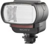
... Remove this unit to a digital still camera while the power is ON, or disconnecting the connection cord while the power is ON can cause the flash to room temperature. • Do not leave or store the flash in temperatures that in room temperature (about 20°C), and the charging time becomes longer. Note...
... Remove this unit to a digital still camera while the power is ON, or disconnecting the connection cord while the power is ON can cause the flash to room temperature. • Do not leave or store the flash in temperatures that in room temperature (about 20°C), and the charging time becomes longer. Note...
Operating Instructions
Page 7
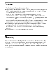
qa qk ql qa Light intensity change button qs Modeling light button qd Back light button qf Test flash button qg READY lamp qh AF illuminator change button qj Display panel qk Connection cord terminal ql Cord clamper 7-GB Mode button 9 qj q; Parts identification 2 1 6 4 3 8 5 7 qh qg qf qd qs 1 Flashing section 2 Wide panel 3 Light exposure meter 4 AF illuminator 5 Advanced accessory shoe 6 Bounce flash angle display 7 Battery cover 8 Rotating knob 9 POWER switch q;
qa qk ql qa Light intensity change button qs Modeling light button qd Back light button qf Test flash button qg READY lamp qh AF illuminator change button qj Display panel qk Connection cord terminal ql Cord clamper 7-GB Mode button 9 qj q; Parts identification 2 1 6 4 3 8 5 7 qh qg qf qd qs 1 Flashing section 2 Wide panel 3 Light exposure meter 4 AF illuminator 5 Advanced accessory shoe 6 Bounce flash angle display 7 Battery cover 8 Rotating knob 9 POWER switch q;
Operating Instructions
Page 12
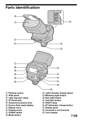
... which is ON can cause the flash to fire erroneously. 12-GB Flashing section 2 1 3 4 5 1 Turn the rotating knob in the direction of the arrow to loosen. 2 Insert this unit. 5 Connect the connection cord to the digital still camera with the flashing section facing forward. 3 Turn the... rotating knob in the direction of the arrow to tighten. 4 Attach the connection cord to the connection cord terminal of the digital still camera. * Depending upon...
... which is ON can cause the flash to fire erroneously. 12-GB Flashing section 2 1 3 4 5 1 Turn the rotating knob in the direction of the arrow to loosen. 2 Insert this unit. 5 Connect the connection cord to the digital still camera with the flashing section facing forward. 3 Turn the... rotating knob in the direction of the arrow to tighten. 4 Attach the connection cord to the connection cord terminal of the digital still camera. * Depending upon...
Operating Instructions
Page 13
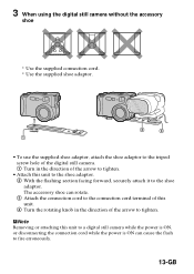
...can rotate. 3 Attach the connection cord to the connection cord terminal of this unit. 4 Turn the rotating knob in the direction of the arrow to fire erroneously. 13-GB PNote Removing or attaching this unit to the shoe adaptor. 2 With the flashing section facing forward, securely attach it... to the shoe adaptor. 3 When using the digital still camera without the accessory shoe * Use the supplied connection cord. * Use the supplied shoe adaptor. 2 3 1 • To use...
...can rotate. 3 Attach the connection cord to the connection cord terminal of this unit. 4 Turn the rotating knob in the direction of the arrow to fire erroneously. 13-GB PNote Removing or attaching this unit to the shoe adaptor. 2 With the flashing section facing forward, securely attach it... to the shoe adaptor. 3 When using the digital still camera without the accessory shoe * Use the supplied connection cord. * Use the supplied shoe adaptor. 2 3 1 • To use...
Operating Instructions
Page 27
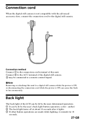
...at about 10 seconds after it lights. 3 If other button operations are made while lighting, it extends for 10 seconds. 27-GB Connection cord When the digital still camera is ON can be connected to a remote control tripod. Connect 2 to fire erroneously. PNote Removing or attaching this... still camera while the power is ON, or disconnecting the connection cord while the power is not compatible with the advanced accessory shoe, connect the connection cord to the digital still camera. 1 2 3 Connection method Connect 1 to the connection cord terminal of the digital still camera. 3 may be lit by...
...at about 10 seconds after it lights. 3 If other button operations are made while lighting, it extends for 10 seconds. 27-GB Connection cord When the digital still camera is ON can be connected to a remote control tripod. Connect 2 to fire erroneously. PNote Removing or attaching this... still camera while the power is ON, or disconnecting the connection cord while the power is not compatible with the advanced accessory shoe, connect the connection cord to the digital still camera. 1 2 3 Connection method Connect 1 to the connection cord terminal of the digital still camera. 3 may be lit by...
Operating Instructions
Page 28
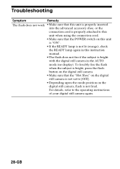
... not work • Make sure that this unit is properly inserted into the advanced accessory shoe, or the connection cord is properly attached to this unit when using the connection cord. • Make sure that the "Hot Shoe" on the digital still camera is not set to [OFF]. • Depending upon ...the mode position on this instruction manual. • The flash does not fire if the subject is not fired. For details, ...
... not work • Make sure that this unit is properly inserted into the advanced accessory shoe, or the connection cord is properly attached to this unit when using the connection cord. • Make sure that the "Hot Shoe" on the digital still camera is not set to [OFF]. • Depending upon ...the mode position on this instruction manual. • The flash does not fire if the subject is not fired. For details, ...
Operating Instructions
Page 29
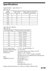
...not included in the dimensions) Mass About 260 g (9.2 oz.) Supplied accessory Shoe adaptor (1) Connection cord (1) Pouch (1) Warranty (1) Operating Instructions (1) Design and specifications are subject to change without notice. 29...-GB Specifications Guide Number equivalent to 16 m (F2) Number of flashes 150 times (using the wide panel) 1/1 32 22 1/2 22 16 1/4 16 11 1/8 11 8 1/16 8 6 1/32 6 4 Auto effective distance *ISO. 100. m Auto flash range 35 mm camera conversion 1.4 2.0 m ~ 22.8 m 2.0 2.0 m ~ 16.0 m 2.8 1.0 m ~ 11.4 m...
...not included in the dimensions) Mass About 260 g (9.2 oz.) Supplied accessory Shoe adaptor (1) Connection cord (1) Pouch (1) Warranty (1) Operating Instructions (1) Design and specifications are subject to change without notice. 29...-GB Specifications Guide Number equivalent to 16 m (F2) Number of flashes 150 times (using the wide panel) 1/1 32 22 1/2 22 16 1/4 16 11 1/8 11 8 1/16 8 6 1/32 6 4 Auto effective distance *ISO. 100. m Auto flash range 35 mm camera conversion 1.4 2.0 m ~ 22.8 m 2.0 2.0 m ~ 16.0 m 2.8 1.0 m ~ 11.4 m...