

Warranty Card
Page 1
... service assistance or resolution of protection, to any part of the Product, including the antenna. PARTS: In addition, Sony will repair or replace the Product, at its original packaging or packaging affording an equal degree of a service problem, or for all accessories are for 19" (measured diagonally), or larger screen size through a Sony authorized service facility. This warranty does not cover customer instruction, installation, set up adjustments or signal reception problems...
... service assistance or resolution of protection, to any part of the Product, including the antenna. PARTS: In addition, Sony will repair or replace the Product, at its original packaging or packaging affording an equal degree of a service problem, or for all accessories are for 19" (measured diagonally), or larger screen size through a Sony authorized service facility. This warranty does not cover customer instruction, installation, set up adjustments or signal reception problems...

Child Safety: It Makes A Difference Where Your TV Stands
Page 1
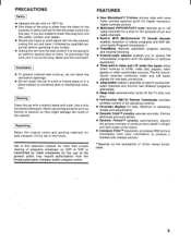
... components). O Remember that can potentially push a TV over and cause injury. As a result TV sets may stimulate a child's curiosity. Convener Electrwirs Associadon www.CE.org/safety As you enjoy you new product, keep these safety tips in appropriately situated on proper TV stands. Use appropriate angle braces, straps and anchors to support the weight, shape and size...
... components). O Remember that can potentially push a TV over and cause injury. As a result TV sets may stimulate a child's curiosity. Convener Electrwirs Associadon www.CE.org/safety As you enjoy you new product, keep these safety tips in appropriately situated on proper TV stands. Use appropriate angle braces, straps and anchors to support the weight, shape and size...
Primary User Manual
Page 1
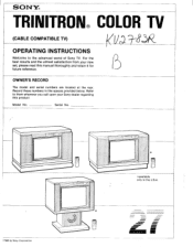
Record these numbers in the U.S.A. 11111111• IME Model No. Refer to the advanced world of Sony TV. SONY® TRINITRON® COLOR TV (CABLE COMPATIBLE TV) OPERATING INSTRUCTIONS Welcome to them whenever you call upon your new set, please read this product. Serial No. )1985 by Sony Corporation * available only in the spaces provided below. For the best results and the utmost satisfaction from your Sony dealer regarding this manual thoroughly and retain it for future reference. OWNER'S RECORD The model and serial numbers are located at the rear.
Record these numbers in the U.S.A. 11111111• IME Model No. Refer to the advanced world of Sony TV. SONY® TRINITRON® COLOR TV (CABLE COMPATIBLE TV) OPERATING INSTRUCTIONS Welcome to them whenever you call upon your new set, please read this product. Serial No. )1985 by Sony Corporation * available only in the spaces provided below. For the best results and the utmost satisfaction from your Sony dealer regarding this manual thoroughly and retain it for future reference. OWNER'S RECORD The model and serial numbers are located at the rear.

Primary User Manual
Page 2
... the set the channel BLOCK 11 Applications with other optional equipment 12 Connections 13 Optional audio/video connecting cables 13 Enjoying the picture of the equipment connected to the video 1/2/3 input 13 To listen to the sound of the audio source connected to the external audio jacks 13 VCR connection 14 Enjoying FM simulcasted programming 16 Antenna/cable connection 16 Specifications 18 Troubleshooting 19 This manual covers three models. This symbol is intended to alert the user...
... the set the channel BLOCK 11 Applications with other optional equipment 12 Connections 13 Optional audio/video connecting cables 13 Enjoying the picture of the equipment connected to the video 1/2/3 input 13 To listen to the sound of the audio source connected to the external audio jacks 13 VCR connection 14 Enjoying FM simulcasted programming 16 Antenna/cable connection 16 Specifications 18 Troubleshooting 19 This manual covers three models. This symbol is intended to alert the user...
Primary User Manual
Page 3
...-screen displays for easy reference to operating modes and adjustments • Dynamic ColorTM circuitry assures accurate, life-like skintones and pure whites • Dynamic PictureTM circuitry automatically adjusts the picture contrast to produce more . The AV uniconnector receives combined video and L/R audio signals for one easy connection. • Jump button makes it possible to switch quickly between channels and monitor two different programs alternately. • Sleep timer automatically turns off -air and cable channels...
...-screen displays for easy reference to operating modes and adjustments • Dynamic ColorTM circuitry assures accurate, life-like skintones and pure whites • Dynamic PictureTM circuitry automatically adjusts the picture contrast to produce more . The AV uniconnector receives combined video and L/R audio signals for one easy connection. • Jump button makes it possible to switch quickly between channels and monitor two different programs alternately. • Sleep timer automatically turns off -air and cable channels...
Primary User Manual
Page 4
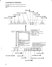
... 12 for the location of green segments show the sound or picture level. On screen display indicates • Channel numbers • "MUTING" or "SLEEP" indications • "VIDEO 1,2 or 3" mode • "MAIN", "SAP", or "BOTH" modes • "EXT-A" mode • TIMER/BLOCK settings Item display indicates • the selected item to be adjusted by the ADJUSTMENT buttons or the "RESET" indicator • the timer according to the internal clock AUTO STEREO CABLE OFF1 rON...
... 12 for the location of green segments show the sound or picture level. On screen display indicates • Channel numbers • "MUTING" or "SLEEP" indications • "VIDEO 1,2 or 3" mode • "MAIN", "SAP", or "BOTH" modes • "EXT-A" mode • TIMER/BLOCK settings Item display indicates • the selected item to be adjusted by the ADJUSTMENT buttons or the "RESET" indicator • the timer according to the internal clock AUTO STEREO CABLE OFF1 rON...
Primary User Manual
Page 5
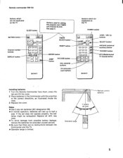
... 0 TIMER/ BLOCK button RESET button ENTER button JUMP button PICTURE button VOL (volume) buttons CH (channel) scan buttons Buttons which are no obstructions between the Commander and the TV. • Operable range is limited. LEVEL +(R)/-(L) buttons SELECT button ANT/AUX (antenna/ auxiliary) button TV/VIDEO button MTS (Multichannel TV Sound) button SONY I 0 YNOS )E o Buttons which are duplicated on the TV SLEEP button Buttons used for extended unused periods. • Be sure that there are not duplicated on the TV POWER switch...
... 0 TIMER/ BLOCK button RESET button ENTER button JUMP button PICTURE button VOL (volume) buttons CH (channel) scan buttons Buttons which are no obstructions between the Commander and the TV. • Operable range is limited. LEVEL +(R)/-(L) buttons SELECT button ANT/AUX (antenna/ auxiliary) button TV/VIDEO button MTS (Multichannel TV Sound) button SONY I 0 YNOS )E o Buttons which are duplicated on the TV SLEEP button Buttons used for extended unused periods. • Be sure that there are not duplicated on the TV POWER switch...

Primary User Manual
Page 6
... stereo sound, select the MAIN mode with your preference, if necessary. To switch quickly between 2 channels, press JUMP. For cable TV channels, set level or press VOLUME +. To listen to change as follows: MAIN SAP =BOTH 6 Cable TV channel chart * Cable TV systems use . To tune in sequence. (For presetting desired channels, see page 9.) The channel display will appear and remain on -screen MAIN indicator appears. This button enables...
... stereo sound, select the MAIN mode with your preference, if necessary. To switch quickly between 2 channels, press JUMP. For cable TV channels, set level or press VOLUME +. To listen to change as follows: MAIN SAP =BOTH 6 Cable TV channel chart * Cable TV systems use . To tune in sequence. (For presetting desired channels, see page 9.) The channel display will appear and remain on -screen MAIN indicator appears. This button enables...
Primary User Manual
Page 7
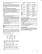
... when the RESET button is displayed. When there is a SAP (Second Audio Program) broadcast Select the SAP mode so that the BOTH indicator is pressed. (A "RESET" indicator will be all cleared and the factory preset levels will change as the sound comes only from the left speaker's right speaker's volume volume SOUND ADJUSTMENT On-screen color-bar displays When any of the above adjustments are inside the front panel. To listen...
... when the RESET button is displayed. When there is a SAP (Second Audio Program) broadcast Select the SAP mode so that the BOTH indicator is pressed. (A "RESET" indicator will be all cleared and the factory preset levels will change as the sound comes only from the left speaker's right speaker's volume volume SOUND ADJUSTMENT On-screen color-bar displays When any of the above adjustments are inside the front panel. To listen...
Primary User Manual
Page 8
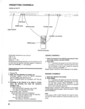
... in "ADDING CHANNELS". PREPARATION 1 Turn on the screen, indicating that the channel will appear on the left of the channel display on TV. 2 Make sure the following and make the necessary changes if any. • CABLE selector For VHF and UHF channels, set . On-screen "VIDEO 1, 2 or 3" or "EXT-A" indicators and the VIDEO lamp should be added by pressing the channel number buttons and then ENTER...
... in "ADDING CHANNELS". PREPARATION 1 Turn on the screen, indicating that the channel will appear on the left of the channel display on TV. 2 Make sure the following and make the necessary changes if any. • CABLE selector For VHF and UHF channels, set . On-screen "VIDEO 1, 2 or 3" or "EXT-A" indicators and the VIDEO lamp should be added by pressing the channel number buttons and then ENTER...

Primary User Manual
Page 9
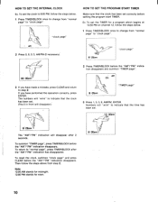
... on the screen at the time set the clock correctly to activate the program start TIMER. CLEAR button Used to deactivate or reactivate the program start TIMER and channel BLOCK. SONY 40 TIMER OFF/REPEAT button Used to erase the time and channel number from the set . The illustration shows how to change the "pages", press the TIMER/BLOCK button as illustrated below . TO stands for setting the internal clock, program start TIMER and channel BLOCK...
... on the screen at the time set the clock correctly to activate the program start TIMER. CLEAR button Used to deactivate or reactivate the program start TIMER and channel BLOCK. SONY 40 TIMER OFF/REPEAT button Used to erase the time and channel number from the set . The illustration shows how to change the "pages", press the TIMER/BLOCK button as illustrated below . TO stands for setting the internal clock, program start TIMER and channel BLOCK...
Primary User Manual
Page 10
To set the TIMER for noon. 8:05pm 10 Numbers will "wink" to indicate that the time has been set correctly before the "AM"/"PM" indication disappears. To reset the clock, summon "clock page" and press CLEAR before the "AM"/"PM" indication disappears and summon "TIMER page". ...change from step 2. Note 12:00 AM stands for midnight. 12:00 PM stands for a program which begins at 10:30 PM on channel 12, follow the steps below . 1 Press TIMER/BLOCK once to "normal page", press TIMER/BLOCK after 2 seconds. If you have performed the operation correctly, press ENTER. Am "TIMER...
To set the TIMER for noon. 8:05pm 10 Numbers will "wink" to indicate that the time has been set correctly before the "AM"/"PM" indication disappears. To reset the clock, summon "clock page" and press CLEAR before the "AM"/"PM" indication disappears and summon "TIMER page". ...change from step 2. Note 12:00 AM stands for midnight. 12:00 PM stands for a program which begins at 10:30 PM on channel 12, follow the steps below . 1 Press TIMER/BLOCK once to "normal page", press TIMER/BLOCK after 2 seconds. If you have performed the operation correctly, press ENTER. Am "TIMER...
Primary User Manual
Page 11
... the VIDEO INPUT 3 jacks, set to "EXT-AUDIO" MONITOR OUTPUT jacks (phono type) Connect to the video and audio input jacks of the VIDEO INPUT 1. to video output jack AUDIO L jack O (phono, white) to audio L (left audio jack of a video cassette recorder or color monitor. Either the TV or VCR signal selected by the TV/VIDEO button is monaural, connect it to the left channel, monaural) output jack AUDIO R jack O (phono, red) to audio R (right channel) output jack *You will achieve better picture and sound...
... the VIDEO INPUT 3 jacks, set to "EXT-AUDIO" MONITOR OUTPUT jacks (phono type) Connect to the video and audio input jacks of the VIDEO INPUT 1. to video output jack AUDIO L jack O (phono, white) to audio L (left audio jack of a video cassette recorder or color monitor. Either the TV or VCR signal selected by the TV/VIDEO button is monaural, connect it to the left channel, monaural) output jack AUDIO R jack O (phono, red) to audio R (right channel) output jack *You will achieve better picture and sound...
Primary User Manual
Page 12
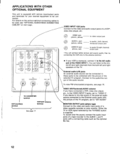
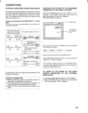
... on-screen "EXT-A" appears. 13 The channel number buttons on the Remote Commander or the channel scan buttons will change as necessary until the "VIDEO 1, 2 or 3" indicator of the VIDEO input jacks from appears. VIDEO lamp -VIDEO 1 / The picture of the possible connections. TO LISTEN TO THE SOUND OF THE AUDIO SOURCE CONNECTED TO THE EXTERNAL AUDIO JACKS 1 Set VIDEO 3/EXT-ADUIO selector to "EXT-AUDIO". 2 Press TV/VIDEO button as many times as follows: VIDEO 1 VIDEO 2 VIDEO 3* TV channel Video (phono-type) 6 Audio (phono-type...
... on-screen "EXT-A" appears. 13 The channel number buttons on the Remote Commander or the channel scan buttons will change as necessary until the "VIDEO 1, 2 or 3" indicator of the VIDEO input jacks from appears. VIDEO lamp -VIDEO 1 / The picture of the possible connections. TO LISTEN TO THE SOUND OF THE AUDIO SOURCE CONNECTED TO THE EXTERNAL AUDIO JACKS 1 Set VIDEO 3/EXT-ADUIO selector to "EXT-AUDIO". 2 Press TV/VIDEO button as many times as follows: VIDEO 1 VIDEO 2 VIDEO 3* TV channel Video (phono-type) 6 Audio (phono-type...

Primary User Manual
Page 13
... (red) to VIDEO INPUT AUDIO R to audio output i 0 VMC-2P3 (optional) to video out If you will be able to... • View the playback of receiving TV broadcasts Caution Television programs, films, video tapes and other materials may be copyrighted. VCR CONNECTION Keep the VCR away from the TV, if the display or sound is equipped with a MULTI CONNECTOR, use the optional VMC-220S video monitor cable and connect the...
... (red) to VIDEO INPUT AUDIO R to audio output i 0 VMC-2P3 (optional) to video out If you will be able to... • View the playback of receiving TV broadcasts Caution Television programs, films, video tapes and other materials may be copyrighted. VCR CONNECTION Keep the VCR away from the TV, if the display or sound is equipped with a MULTI CONNECTOR, use the optional VMC-220S video monitor cable and connect the...

Primary User Manual
Page 14
For selecting the desired video source, see page 13. ILT.r 00 4.) to video input jli& VMC-2P3 (optional) to AUDIO R VCR 00 0 PI-- MONITOR OUTPUT O (yellow) to VIDEO 00 (white) to AUDIO L 00 (red) to audio input 15 Editing tapes by connecting a VCR to the MONITOR OUTPUT jacks If a VCR is connected to the MONITOR OUTPUT jacks besides another VCR, video disc player, etc., connected to the VIDEO INPUT 1/2/3 jacks, you will be able to edit your own tapes by recording the selected video source (including the TV programs) displayed on the screen.
For selecting the desired video source, see page 13. ILT.r 00 4.) to video input jli& VMC-2P3 (optional) to AUDIO R VCR 00 0 PI-- MONITOR OUTPUT O (yellow) to VIDEO 00 (white) to AUDIO L 00 (red) to audio input 15 Editing tapes by connecting a VCR to the MONITOR OUTPUT jacks If a VCR is connected to the MONITOR OUTPUT jacks besides another VCR, video disc player, etc., connected to the VIDEO INPUT 1/2/3 jacks, you will be able to edit your own tapes by recording the selected video source (including the TV programs) displayed on the screen.
Primary User Manual
Page 15
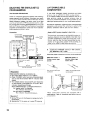
... cable type. A Combination VHF/UHF antenna,* VHF antenna, UHF antenna or CATV cable Select the proper connector according to both the TV tuner and an FM tuner/receiver, these cable programs can be connected to the grounding system of TV VHF/UHF 15 mm 11-\ (5/s in stereo over the TV's doublesided speakers as practical. Rear of the building, as close to "EXT-AUDIO". • Press TV/VIDEO button...
... cable type. A Combination VHF/UHF antenna,* VHF antenna, UHF antenna or CATV cable Select the proper connector according to both the TV tuner and an FM tuner/receiver, these cable programs can be connected to the grounding system of TV VHF/UHF 15 mm 11-\ (5/s in stereo over the TV's doublesided speakers as practical. Rear of the building, as close to "EXT-AUDIO". • Press TV/VIDEO button...

Primary User Manual
Page 16
... Rear of the cable TV channels over 37 (W+1). When connecting both VHF and UHF antennas are connected Prepare the VHF antenna end using the appropriate connector as a U/V mixer. AUX TO CONVERTER EAC-66 VHF/UHF When the cable is connected to the normal cable connection. Attach an optional EAC-66 U/V mixer to the TV antenna terminal, and connect the cables to the U/V mixer. Pay TV Cable Input 1 Output...
... Rear of the cable TV channels over 37 (W+1). When connecting both VHF and UHF antennas are connected Prepare the VHF antenna end using the appropriate connector as a U/V mixer. AUX TO CONVERTER EAC-66 VHF/UHF When the cable is connected to the normal cable connection. Attach an optional EAC-66 U/V mixer to the TV antenna terminal, and connect the cables to the U/V mixer. Pay TV Cable Input 1 Output...
Primary User Manual
Page 17
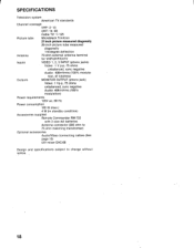
SPECIFICATIONS Television system American TV standards Channel coverage VHF: 2-13 UHF: 14-69 Cable TV: 1-125 Picture tube Microblack Trinitron 27-inch picture measured diagonally 28-inch picture tube measured diagonally 110-degree deflection Antenna 75-ohm external antenna terminal for VHF/UHF/CATV Inputs VIDEO 1, 2, 3 INPUT (phono jacks) Video: 1 V p-p, 75 ohms unbalanced, sync negative Audio: 408mVrms (100% modula- tion, 47 kilohms) Outputs MONITOR OUTPUT (phono jack) Video: 1 Vp-p, 75 ohms unbalanced...
SPECIFICATIONS Television system American TV standards Channel coverage VHF: 2-13 UHF: 14-69 Cable TV: 1-125 Picture tube Microblack Trinitron 27-inch picture measured diagonally 28-inch picture tube measured diagonally 110-degree deflection Antenna 75-ohm external antenna terminal for VHF/UHF/CATV Inputs VIDEO 1, 2, 3 INPUT (phono jacks) Video: 1 V p-p, 75 ohms unbalanced, sync negative Audio: 408mVrms (100% modula- tion, 47 kilohms) Outputs MONITOR OUTPUT (phono jack) Video: 1 Vp-p, 75 ohms unbalanced...
Primary User Manual
Page 18
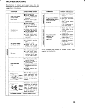
... the TV/ VIDEO button is set correctly. • Are the connections made with the ADJUSTMENT buttons. • Check antenna/cable connections. • Press VOLUME +. • Release MUTING on ? • Is the connected equipment set correctly. Power in picture and sound can often be solved, contact your nearest service facility. Snow and noise only _ - • Is it a color program? • Is the color adjust- A highly direc- It could be station trouble. 19
... the TV/ VIDEO button is set correctly. • Are the connections made with the ADJUSTMENT buttons. • Check antenna/cable connections. • Press VOLUME +. • Release MUTING on ? • Is the connected equipment set correctly. Power in picture and sound can often be solved, contact your nearest service facility. Snow and noise only _ - • Is it a color program? • Is the color adjust- A highly direc- It could be station trouble. 19


