Help
Page 2
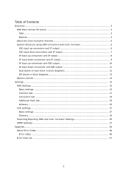
... of each block in block diagrams 12 DR blocks in block diagrams 13 Option Licenses ...14 Settings ...15 HDR Settings ...15 Basic settings ...15 Common tab ...17 Conversion tab 19 Additional Paint tab 24 Glossary ...25 CCR Settings ...27 Basic settings ...27 Glossary ...34 Importing/Exporting HDR and Color Corrector Settings 35 SNMP Settings...37 Appendix ...40 About Error Codes 40 Error codes ...40 Error Code List ...41 2
... of each block in block diagrams 12 DR blocks in block diagrams 13 Option Licenses ...14 Settings ...15 HDR Settings ...15 Basic settings ...15 Common tab ...17 Conversion tab 19 Additional Paint tab 24 Glossary ...25 CCR Settings ...27 Basic settings ...27 Glossary ...34 Importing/Exporting HDR and Color Corrector Settings 35 SNMP Settings...37 Appendix ...40 About Error Codes 40 Error codes ...40 Error Code List ...41 2
Help
Page 3
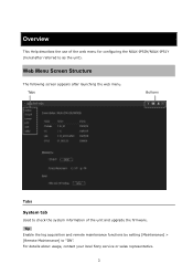
Tip Enable the log acquisition and remote maintenance functions by setting [Maintenance] > [Remote Maintenance] to as the unit). Tabs Buttons Tabs System tab Used to check the system information of the web menu for configuring the NXLK-IP50Y/NXLK-IP51Y (hereinafter referred to "ON". For details about usage, contact your local Sony service or sales representative. 3 Overview This Help describes the use of the unit and upgrade the firmware. Web Menu Screen Structure The following screen appears after launching the web menu.
Tip Enable the log acquisition and remote maintenance functions by setting [Maintenance] > [Remote Maintenance] to as the unit). Tabs Buttons Tabs System tab Used to check the system information of the web menu for configuring the NXLK-IP50Y/NXLK-IP51Y (hereinafter referred to "ON". For details about usage, contact your local Sony service or sales representative. 3 Overview This Help describes the use of the unit and upgrade the firmware. Web Menu Screen Structure The following screen appears after launching the web menu.
Help
Page 4
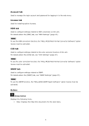
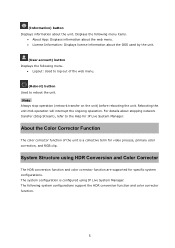
...; Help: Displays the Help (this document) for logging in to the web menu. For details about the [SNMP] tab, see "HDR Settings" (page 15). SNMP tab Used to configure settings related to SNMP. Note To use the HDR conversion function, the "NXLL-MC50 Multi Format Converter Software" option license must be activated. Account tab Used to manage the login account and password for the web menu...
...; Help: Displays the Help (this document) for logging in to the web menu. For details about the [SNMP] tab, see "HDR Settings" (page 15). SNMP tab Used to configure settings related to SNMP. Note To use the HDR conversion function, the "NXLL-MC50 Multi Format Converter Software" option license must be activated. Account tab Used to manage the login account and password for the web menu...
Help
Page 5
... IP Live System Manager. The following menu. • Logout: Used to log out of the unit is configured using HDR Conversion and Color Corrector The HDR conversion function and color corrector function are supported for specific system configurations. For details about stopping network transfer (Stop Stream), refer to reboot the unit. (Information) button Displays information about the OSS used by the unit. (User account) button...
... IP Live System Manager. The following menu. • Logout: Used to log out of the unit is configured using HDR Conversion and Color Corrector The HDR conversion function and color corrector function are supported for specific system configurations. For details about stopping network transfer (Stop Stream), refer to reboot the unit. (Information) button Displays information about the OSS used by the unit. (User account) button...
Help
Page 6
For NXLK-IP50Y Connection Block diagram For NXLK-IP51Y Connection Block diagram 6 For details about each block in the block diagram, see "Description of each block in block diagrams" (page 12). SDI input up-conversion and IP output This system configuration takes an HD signal input on an SDI connector and up -converted from an HD signal and the SDI-input HD signal itself) are output to the IP network. Two signals (a signal up -converts it for output over an IP network.
For NXLK-IP50Y Connection Block diagram For NXLK-IP51Y Connection Block diagram 6 For details about each block in the block diagram, see "Description of each block in block diagrams" (page 12). SDI input up-conversion and IP output This system configuration takes an HD signal input on an SDI connector and up -converted from an HD signal and the SDI-input HD signal itself) are output to the IP network. Two signals (a signal up -converts it for output over an IP network.
Help
Page 7
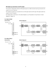
For NXLK-IP50Y Connection Block diagram For NXLK-IP51Y Connection Block diagram 7 SDI input down-conversion and IP output This system configuration takes a QFHD signal input on the SDI connectors and down -converted from a QFHD signal and the SDI-input QFHD signal itself) are output to an HD signal for output over an IP network. Two signals (a signal down -converts it to the IP network. For details about each block in the block diagram, see "Description of each block in block diagrams" (page 12).
For NXLK-IP50Y Connection Block diagram For NXLK-IP51Y Connection Block diagram 7 SDI input down-conversion and IP output This system configuration takes a QFHD signal input on the SDI connectors and down -converted from a QFHD signal and the SDI-input QFHD signal itself) are output to an HD signal for output over an IP network. Two signals (a signal down -converts it to the IP network. For details about each block in the block diagram, see "Description of each block in block diagrams" (page 12).
Help
Page 8
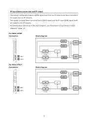
For details about each block in the block diagram, see "Description of each block in block diagrams" (page 12). IP input up -converts it for output over an IP network. For NXLK-IP50Y Connection Block diagram For NXLK-IP51Y Connection Block diagram 8 Two signals (a signal up-converted from an IP network and up -conversion and IP output This system configuration takes an HD signal input from an HD signal and the IP-input HD signal itself) are output to the IP network.
For details about each block in the block diagram, see "Description of each block in block diagrams" (page 12). IP input up -converts it for output over an IP network. For NXLK-IP50Y Connection Block diagram For NXLK-IP51Y Connection Block diagram 8 Two signals (a signal up-converted from an IP network and up -conversion and IP output This system configuration takes an HD signal input from an HD signal and the IP-input HD signal itself) are output to the IP network.
Help
Page 9
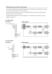
Two signals (a signal down-converted from an IP network and down -conversion and IP output This system configuration takes a QFHD signal input from a QFHD signal and the IP-input QFHD signal itself) are output to the IP network. For details about each block in the block diagram, see "Description of each block in block diagrams" (page 12). For NXLK-IP50Y Connection Block diagram For NXLK-IP51Y Connection Block diagram 9 IP input down -converts it for output over an IP network.
Two signals (a signal down-converted from an IP network and down -conversion and IP output This system configuration takes a QFHD signal input from a QFHD signal and the IP-input QFHD signal itself) are output to the IP network. For details about each block in the block diagram, see "Description of each block in block diagrams" (page 12). For NXLK-IP50Y Connection Block diagram For NXLK-IP51Y Connection Block diagram 9 IP input down -converts it for output over an IP network.
Help
Page 10
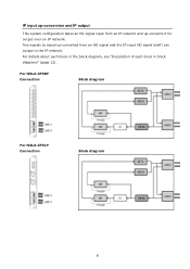
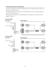
IP input up-conversion and SDI output This system configuration takes an HD signal input from an IP network and up -converted from an HD signal and the IP-input HD signal itself) are output on the SDI connectors. For NXLK-IP50Y Connection Block diagram For NXLK-IP51Y Connection Block diagram 10 For details about each block in the block diagram, see "Description of each block in block diagrams" (page 12). Two signals (a signal up -converts it for output on the SDI connectors.
IP input up-conversion and SDI output This system configuration takes an HD signal input from an IP network and up -converted from an HD signal and the IP-input HD signal itself) are output on the SDI connectors. For NXLK-IP50Y Connection Block diagram For NXLK-IP51Y Connection Block diagram 10 For details about each block in the block diagram, see "Description of each block in block diagrams" (page 12). Two signals (a signal up -converts it for output on the SDI connectors.
Help
Page 12
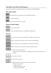
... the symbols used for each block in the block diagrams. SDI input/output 3GQ: QFHD 3G Level A Quad Link SDI 2-Sample Interleave 12G: QFHD 12G SDI HD: HD 3G Level A SDI or 1.5G SDI Network input/output LAN1: Primary LAN LAN2: Secondary LAN (Use in redundancy configuration) Process 4K Tx: Conversion of SDI-input QFHD to IP output (IP transmitter) HD...
... the symbols used for each block in the block diagrams. SDI input/output 3GQ: QFHD 3G Level A Quad Link SDI 2-Sample Interleave 12G: QFHD 12G SDI HD: HD 3G Level A SDI or 1.5G SDI Network input/output LAN1: Primary LAN LAN2: Secondary LAN (Use in redundancy configuration) Process 4K Tx: Conversion of SDI-input QFHD to IP output (IP transmitter) HD...
Help
Page 15
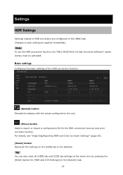
... Converter Software" option license must be activated. Basic settings Configures the basic settings of the HDR conversion function. (Reload) button Reloads the display with the values configured on the [System] tab. 15 Tip You can also reset all the settings on the [HDR] tab to export or import a configuration file for [HDR and CCR Settings] on the unit. (Menu) button Used to the defaults.
... Converter Software" option license must be activated. Basic settings Configures the basic settings of the HDR conversion function. (Reload) button Reloads the display with the values configured on the [System] tab. 15 Tip You can also reset all the settings on the [HDR] tab to export or import a configuration file for [HDR and CCR Settings] on the unit. (Menu) button Used to the defaults.
Help
Page 27
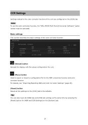
... [CCR] tab. Tip You can also reset all the settings on the [CCR] tab to export or import a configuration file for [HDR and CCR Settings] on the [System] tab. 27 CCR Settings Settings related to the color corrector function of the color corrector function. (Reload) button Reloads the display with the values configured on the unit. (Menu) button Used to the defaults.
... [CCR] tab. Tip You can also reset all the settings on the [CCR] tab to export or import a configuration file for [HDR and CCR Settings] on the [System] tab. 27 CCR Settings Settings related to the color corrector function of the color corrector function. (Reload) button Reloads the display with the values configured on the unit. (Menu) button Used to the defaults.
Help
Page 35
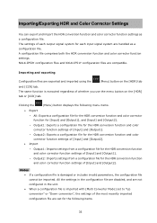
... settings in the unit. • When a configuration file is damaged or includes invalid parameters, the configuration file cannot be imported. NXLK-IP50Y configuration files and NXLK-IP51Y configuration files are handled as a configuration file. The same function is executed regardless of the most recently imported configuration file are not configured in the configuration file are disabled, and are set to "Up conversion" or "Down conversion", the settings of whether you use the menu button...
... settings in the unit. • When a configuration file is damaged or includes invalid parameters, the configuration file cannot be imported. NXLK-IP50Y configuration files and NXLK-IP51Y configuration files are handled as a configuration file. The same function is executed regardless of the most recently imported configuration file are not configured in the configuration file are disabled, and are set to "Up conversion" or "Down conversion", the settings of whether you use the menu button...

Help
Page 38
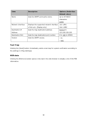
...: Default value) SNMP Agent Enables/disables the SNMP function. • Enable • Disable Port Sets the port number of the unit. (Display only) 2nd: LAN1&LAN2 Version Sets the SNMP version. • V1 & V2C • V2C Mode Displays the access permissions for MIB READ ONLY information. (Display only) Trap Settings Configures settings related to trap notifications to 64 ASCII information. Up to 64 ASCII characters public Network Interface Displays...
...: Default value) SNMP Agent Enables/disables the SNMP function. • Enable • Disable Port Sets the port number of the unit. (Display only) 2nd: LAN1&LAN2 Version Sets the SNMP version. • V1 & V2C • V2C Mode Displays the access permissions for MIB READ ONLY information. (Display only) Trap Settings Configures settings related to trap notifications to 64 ASCII information. Up to 64 ASCII characters public Network Interface Displays...
Help
Page 39
... the [Send] button immediately sends a test trap for system verification according to display a list of the unit. (Display only) Sets the trap destination address. MIB data Clicking the [Retrieve] button opens a new tab in the web browser to the settings in [Trap Settings]. Sets the SNMP version. Displays the supported network interface of the MIB information. 39 Item Name Network Interface Destination IP Address Destination Port Version Description Sets the SNMP...
... the [Send] button immediately sends a test trap for system verification according to display a list of the unit. (Display only) Sets the trap destination address. MIB data Clicking the [Retrieve] button opens a new tab in the web browser to the settings in [Trap Settings]. Sets the SNMP version. Displays the supported network interface of the MIB information. 39 Item Name Network Interface Destination IP Address Destination Port Version Description Sets the SNMP...
Help
Page 40
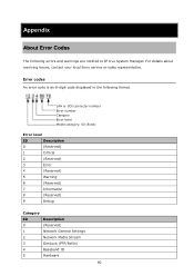
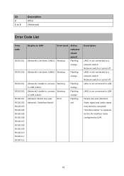
... notified to IP Live System Manager. LAN or SDI connector number Error number Category Error level Model category: 50 (fixed) Error level ID Description 0 (Reserved) 1 Critical 2 (Reserved) 3 Error 4 (Reserved) 5 Warning 6 (Reserved) 7 Information 8 (Reserved) 9 Debug Category ID Description 0 (Reserved) 1 Network General Settings 2 Network Media Stream 3 GenLock (PTP/RefIn) 4 Baseband IO 5 Hardware 40 Appendix About Error Codes The following format. For details about resolving issues, contact your local Sony service or...
... notified to IP Live System Manager. LAN or SDI connector number Error number Category Error level Model category: 50 (fixed) Error level ID Description 0 (Reserved) 1 Critical 2 (Reserved) 3 Error 4 (Reserved) 5 Warning 6 (Reserved) 7 Information 8 (Reserved) 9 Debug Category ID Description 0 (Reserved) 1 Network General Settings 2 Network Media Stream 3 GenLock (PTP/RefIn) 4 Baseband IO 5 Hardware 40 Appendix About Error Codes The following format. For details about resolving issues, contact your local Sony service or...
Help
Page 41
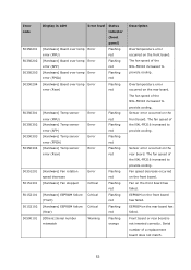
LAN1 is not connected to LSM. "Interface Name" is turned off . LAN2 is not connected to LSM. Network switch is turned off . Packet loss was Error detected. (Interface Name) Flashing orange Flashing orange Flashing red Description LAN1 is not connected to a network switch. ID 9 6 to 8 Description Other (Reserved) Error Code List Error code 50510101 Display in LSM Error level Status indicator (front panel) [Network] Link down (LAN1) Warning Flashing orange 50510102 [Network] Link down (LAN2) Warning Flashing orange 50510201 50510202...
LAN1 is not connected to LSM. "Interface Name" is turned off . LAN2 is not connected to LSM. Network switch is turned off . Packet loss was Error detected. (Interface Name) Flashing orange Flashing orange Flashing red Description LAN1 is not connected to a network switch. ID 9 6 to 8 Description Other (Reserved) Error Code List Error code 50510101 Display in LSM Error level Status indicator (front panel) [Network] Link down (LAN1) Warning Flashing orange 50510102 [Network] Link down (LAN2) Warning Flashing orange 50510201 50510202...
Help
Page 53
... sensor error (SFP) [Hardware] Temp sensor error (FPGA) [Hardware] Temp sensor error (Rear) Error Error Error Error Flashing red Flashing red Flashing red Flashing red 50351201 50151301 [Hardware] Fan rotation speed decrease [Hardware] Fan stopped Error Critical 50152101 50152102 50590101 [Hardware] EEPROM failure (Front) [Hardware] EEPROM failure (Rear) [Others] Serial number mismatch Critical Critical Warning Flashing red Flashing red Flashing red Flashing red Flashing orange Description Overtemperature error occurred on the front board. Fan on the rear board has failed. The...
... sensor error (SFP) [Hardware] Temp sensor error (FPGA) [Hardware] Temp sensor error (Rear) Error Error Error Error Flashing red Flashing red Flashing red Flashing red 50351201 50151301 [Hardware] Fan rotation speed decrease [Hardware] Fan stopped Error Critical 50152101 50152102 50590101 [Hardware] EEPROM failure (Front) [Hardware] EEPROM failure (Rear) [Others] Serial number mismatch Critical Critical Warning Flashing red Flashing red Flashing red Flashing red Flashing orange Description Overtemperature error occurred on the front board. Fan on the rear board has failed. The...
Operating Instructions
Page 1
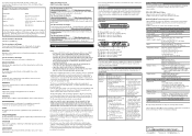
... can radiate radio frequency energy and, if not installed and used to connect the equipment to the following two conditions: (1) This device may call: Sony Customer Information Service Center 1-800-222-7669 or http:// www.sony.com/ Supplier's Declaration of Conformity Trade Name Model Responsible party Address Telephone Number : SONY : NXLK-IP50Y/NXLK-IP51Y : Sony Electronics Inc. : 16535 Via Esprillo, San Diego, CA 92127 U.S.A. : 858...
... can radiate radio frequency energy and, if not installed and used to connect the equipment to the following two conditions: (1) This device may call: Sony Customer Information Service Center 1-800-222-7669 or http:// www.sony.com/ Supplier's Declaration of Conformity Trade Name Model Responsible party Address Telephone Number : SONY : NXLK-IP50Y/NXLK-IP51Y : Sony Electronics Inc. : 16535 Via Esprillo, San Diego, CA 92127 U.S.A. : 858...
Operating Instructions
Page 2
... the unit by the status indicator of Sony's limited warranty applicable to blink red after checking these items, contact your local Sony service representative. Copper DAC (Direct Attach Cable) is strongly recommended to access the Control window via a Web browser and change the access limitation settings from a cold to green after making settings or after checking these items and restarting the unit, stop using SFP28 transceiver module) For details on the...
... the unit by the status indicator of Sony's limited warranty applicable to blink red after checking these items, contact your local Sony service representative. Copper DAC (Direct Attach Cable) is strongly recommended to access the Control window via a Web browser and change the access limitation settings from a cold to green after making settings or after checking these items and restarting the unit, stop using SFP28 transceiver module) For details on the...