
User Manual
Page 55
... and Function of Parts and Controls ....... 7 (GB) Front / Rear / Right Side 7 (GB) 1 (standby) Switch / Indicator Section 8 (GB) Control Button Section (Rear 8 (GB) Connector Panel 9 (GB) Remote Commander RM-42B 11 (GB) Caution 13 (GB) Connections 14 (GB) Connecting the AC Power Cord 14 (GB) Attaching the ferrite core... (PFM-42B2/42B2E only 14 (GB) Connection Example 15 (GB) Using On-screen Menus 20 (GB) Operating Through Menus 20 (GB) GB Menu Guide...
... and Function of Parts and Controls ....... 7 (GB) Front / Rear / Right Side 7 (GB) 1 (standby) Switch / Indicator Section 8 (GB) Control Button Section (Rear 8 (GB) Connector Panel 9 (GB) Remote Commander RM-42B 11 (GB) Caution 13 (GB) Connections 14 (GB) Connecting the AC Power Cord 14 (GB) Attaching the ferrite core... (PFM-42B2/42B2E only 14 (GB) Connection Example 15 (GB) Using On-screen Menus 20 (GB) Operating Through Menus 20 (GB) GB Menu Guide...

User Manual
Page 57
...On installation • Allow adequate air circulation to use the infrared communication equipment, move it is made, when this unit, contact your authorized Sony dealer. 5 (GB) If light ghosting (image burn-in) occurs, it may become less conspicuous, but once burn-in a place subject...infrared communication equipment (e.g., infrared cordless headphones or microphones) is used for a long period of video or imaging software to avoid touching the panel directly. These do not indicate malfunction. • If you continue to another location, repack it over the entire screen. If you...
...On installation • Allow adequate air circulation to use the infrared communication equipment, move it is made, when this unit, contact your authorized Sony dealer. 5 (GB) If light ghosting (image burn-in) occurs, it may become less conspicuous, but once burn-in a place subject...infrared communication equipment (e.g., infrared cordless headphones or microphones) is used for a long period of video or imaging software to avoid touching the panel directly. These do not indicate malfunction. • If you continue to another location, repack it over the entire screen. If you...

User Manual
Page 58
... settings. • ID control • Self-diagnosis function • Remote (RS-232C) connector (D-sub 9-pin) • Accepts infrared Sony Remote Commanders using SIRCS code. • Vertical setup • Closed caption decoder • Screen saver to reduce afterimage or ghosting. Flexibility... a finely-detailed HDTV or PC image. Video, HDTV, PC, etc. Features Features The PFM-42B1/42B2/42B1E/42B2E series are 16:9 42-inch flat panel displays utilizing a PDP (Plasma Display Panel), which is applied to local regulations...1) Windows is a registered trademark of the Microsoft Corporation ...
... settings. • ID control • Self-diagnosis function • Remote (RS-232C) connector (D-sub 9-pin) • Accepts infrared Sony Remote Commanders using SIRCS code. • Vertical setup • Closed caption decoder • Screen saver to reduce afterimage or ghosting. Flexibility... a finely-detailed HDTV or PC image. Video, HDTV, PC, etc. Features Features The PFM-42B1/42B2/42B1E/42B2E series are 16:9 42-inch flat panel displays utilizing a PDP (Plasma Display Panel), which is applied to local regulations...1) Windows is a registered trademark of the Microsoft Corporation ...

User Manual
Page 59
... the 1 (standby) switch / indicator section, see "1 (standby) Switch / Indicator Section" on page 8 (GB). 2 Control button section For details on the control button section, see "Connector Panel" on page 8 (GB). 3 Carrying handles 4 -AC IN socket Connect the supplied AC power cord to this socket and to install the stand (not supplied). 6 Connector...
... the 1 (standby) switch / indicator section, see "1 (standby) Switch / Indicator Section" on page 8 (GB). 2 Control button section For details on the control button section, see "Connector Panel" on page 8 (GB). 3 Carrying handles 4 -AC IN socket Connect the supplied AC power cord to this socket and to install the stand (not supplied). 6 Connector...
User Manual
Page 61
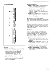
...Connects to the audio output of a piece of video equipment. 9 (GB) Connects to the composite video signal output of a piece of video equipment. Connector Panel 1 2 3 4 5 1 INPUT1 connectors RGB/YUV (D-sub 15-pin): Connects to the audio output of a computer or a piece of video equipment....of a computer or a piece of video equipment. AUDIO (Stereo minijack): Inputs an audio signal. For details, contact your authorized Sony dealer. 5 VIDEO connectors The PFM-42B1E/42B2E are not equipped with VIDEO connectors. COMPOSITE OUT (BNC-type): Connects to the composite video signal input of a ...
...Connects to the audio output of a piece of video equipment. 9 (GB) Connects to the composite video signal output of a piece of video equipment. Connector Panel 1 2 3 4 5 1 INPUT1 connectors RGB/YUV (D-sub 15-pin): Connects to the audio output of a computer or a piece of video equipment....of a computer or a piece of video equipment. AUDIO (Stereo minijack): Inputs an audio signal. For details, contact your authorized Sony dealer. 5 VIDEO connectors The PFM-42B1E/42B2E are not equipped with VIDEO connectors. COMPOSITE OUT (BNC-type): Connects to the composite video signal input of a ...

User Manual
Page 63
... a 10/ 100BASE-T LAN cable. 4 Keyboard connector Connect a USB keyboard. 5 Mouse connector Connect a USB mouse. 1 POWER ON switch Press to the Y/ C output connector of the display panel. Location and Function of Parts and Controls Remote Commander RM-42B 1 qs 2 3 qd 4 5 qf 6 Y/C 1 qg VIDEO IN COMPOSITE qh qj 7 qk 8 ql 2 9 w; 0 wa qa 3 4 5 1 VIDEO...
... a 10/ 100BASE-T LAN cable. 4 Keyboard connector Connect a USB keyboard. 5 Mouse connector Connect a USB mouse. 1 POWER ON switch Press to the Y/ C output connector of the display panel. Location and Function of Parts and Controls Remote Commander RM-42B 1 qs 2 3 qd 4 5 qf 6 Y/C 1 qg VIDEO IN COMPOSITE qh qj 7 qk 8 ql 2 9 w; 0 wa qa 3 4 5 1 VIDEO...

User Manual
Page 64
... to select the desired item in correct polarity. For details about the index number, see "Operating a Specific Display With the Remote Commander" on the display panel, press to return to return from among the VIDEO connectors. wa CONTRAST +/- qj SELECT +M/-m button Press to move the cursor (B) to an item or to...
... to select the desired item in correct polarity. For details about the index number, see "Operating a Specific Display With the Remote Commander" on the display panel, press to return to return from among the VIDEO connectors. wa CONTRAST +/- qj SELECT +M/-m button Press to move the cursor (B) to an item or to...
User Manual
Page 72
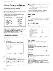
...press ENTER to the previous menu. The setting is input. This function works only for menu operations. The main menu appears on the display panel. 4 Press v / V to adjust or select the setting and press ENTER to select a menu. Remote Commander Control button section The buttons... Note "- - - -" appears next to the normal screen, press the MENU button repeatedly until the menu disappears. The availability depends on the display panel. 3 Press v / V to move the cursor (B) and press ENTER to set. Configuration of input signal. Using On-screen Menus Using On-screen...
...press ENTER to the previous menu. The setting is input. This function works only for menu operations. The main menu appears on the display panel. 4 Press v / V to adjust or select the setting and press ENTER to select a menu. Remote Commander Control button section The buttons... Note "- - - -" appears next to the normal screen, press the MENU button repeatedly until the menu disappears. The availability depends on the display panel. 3 Press v / V to move the cursor (B) and press ENTER to set. Configuration of input signal. Using On-screen Menus Using On-screen...

User Manual
Page 74
...E M O R Y LOAD e; wl LOAD Recalls the preset settings. SAVE Saves the settings. wd POWER CONTROL Sets the length of the display. wj SERIAL REMOTE (PFM-42B2/42B2E only) Setting the Serial Remote. For details, see "Selecting the On-screen Language" on page 39 (GB). MEMORY menu This menu is used... index number of time until the system goes into the power saving mode. CORNER: Sets the point of origin at the center of the display panel when the power is used for remote control settings. SAVE SE L ECT S E T ENTER E N D MENU For details, see "Controlling Power On/Off...
...E M O R Y LOAD e; wl LOAD Recalls the preset settings. SAVE Saves the settings. wd POWER CONTROL Sets the length of the display. wj SERIAL REMOTE (PFM-42B2/42B2E only) Setting the Serial Remote. For details, see "Selecting the On-screen Language" on page 39 (GB). MEMORY menu This menu is used... index number of time until the system goes into the power saving mode. CORNER: Sets the point of origin at the center of the display panel when the power is used for remote control settings. SAVE SE L ECT S E T ENTER E N D MENU For details, see "Controlling Power On/Off...
User Manual
Page 76
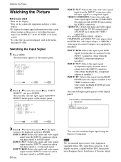
...signal. INPUT1 RGB: Selects the audio and video signal input from the COMPOSITE IN connector and AUDIO IN jack among the VIDEO connectors. (For the PFM-42B1E/42B2E, VIDEO COMPOSITE and VIDEO Y/C only appear when the BKM-B10 video input adaptor or BKM-B13 video input & control S adaptor (not... signal is an RGB signal. 24 (GB) You can also switch the input signal using the Remote Commander. The main menu appears on the display panel. If the display receives a signal without TBC, the picture may disappear due to be displayed and press ENTER. MA I N MENU I NPUT SELECT P I C CONTROL P I C S...
...signal. INPUT1 RGB: Selects the audio and video signal input from the COMPOSITE IN connector and AUDIO IN jack among the VIDEO connectors. (For the PFM-42B1E/42B2E, VIDEO COMPOSITE and VIDEO Y/C only appear when the BKM-B10 video input adaptor or BKM-B13 video input & control S adaptor (not... signal is an RGB signal. 24 (GB) You can also switch the input signal using the Remote Commander. The main menu appears on the display panel. If the display receives a signal without TBC, the picture may disappear due to be displayed and press ENTER. MA I N MENU I NPUT SELECT P I C CONTROL P I C S...
User Manual
Page 77
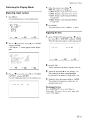
... the upper-right corner of the hour is shown in cyan. 4 Similarly, adjust the minute and press ENTER. The following menu appears on the display panel. VGA : OF F C LOSED CAP T I ON : OF F COLOR SYS T EM : AUTO YUV LEVEL : SMP T E SCREEN F I ON : OF F SE L ECT S E T ENTER E N... Adjust the hour with v / V. Switching the Display Mode Displaying closed captions 1 Press MENU. The main menu appears on the display panel. CAPT1: Displays caption1 over the picture. The setting for the minute is entered and the second is not displayed. CAPT2: Displays caption2 over...
... the upper-right corner of the hour is shown in cyan. 4 Similarly, adjust the minute and press ENTER. The following menu appears on the display panel. VGA : OF F C LOSED CAP T I ON : OF F COLOR SYS T EM : AUTO YUV LEVEL : SMP T E SCREEN F I ON : OF F SE L ECT S E T ENTER E N... Adjust the hour with v / V. Switching the Display Mode Displaying closed captions 1 Press MENU. The main menu appears on the display panel. CAPT1: Displays caption1 over the picture. The setting for the minute is entered and the second is not displayed. CAPT2: Displays caption2 over...

User Manual
Page 78
... cursor (B) to OFF and press ENTER. Watching the Picture Input Signal and Display Status Information Input signal and display status information appears on the display panel for about five seconds when the power is disabled. The following menu appears on the Remote Commander, regardless of the above . D I NPUT 1 RGB 16 : 30...) The factory default is ON. Note You can display the input signal information and the time anytime by pressing the DISPLAY button on the display panel.
... cursor (B) to OFF and press ENTER. Watching the Picture Input Signal and Display Status Information Input signal and display status information appears on the display panel for about five seconds when the power is disabled. The following menu appears on the Remote Commander, regardless of the above . D I NPUT 1 RGB 16 : 30...) The factory default is ON. Note You can display the input signal information and the time anytime by pressing the DISPLAY button on the display panel.
User Manual
Page 80
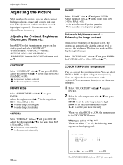
...: 1 RED GA I N GREEN GA I N B LUE GA I N NAME SE T : 128 : 128 : 128 28 (GB) SE L ECT A D J U S T ENTER E N D MENU The PFM-42B1/42B1E displays "255" for each gain more precisely When you select "1" to six characters in the range from the PIC CONTROL menu with v / V. Adjusting the... Contrast, Brightness, Chroma, and Phase, etc. Press MENU so that the main menu appears on the display panel and select "CONTRAST", "BRIGHTNESS", "CHROMA", "PHASE", "PICTURE AGC", "COLOR TEMP" or "SHARPNESS" from MIN (0) to set the color temperature. ...
...: 1 RED GA I N GREEN GA I N B LUE GA I N NAME SE T : 128 : 128 : 128 28 (GB) SE L ECT A D J U S T ENTER E N D MENU The PFM-42B1/42B1E displays "255" for each gain more precisely When you select "1" to six characters in the range from the PIC CONTROL menu with v / V. Adjusting the... Contrast, Brightness, Chroma, and Phase, etc. Press MENU so that the main menu appears on the display panel and select "CONTRAST", "BRIGHTNESS", "CHROMA", "PHASE", "PICTURE AGC", "COLOR TEMP" or "SHARPNESS" from MIN (0) to set the color temperature. ...
User Manual
Page 81
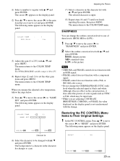
... picture of a character in the character list with v / V and press ENTER. RESET : NO SE L ECT S E T ENTER E N D MENU 29 (GB) The PFM-42B1/42B1E variable range is black-and-white. The menu returns to the COLOR TEMP menu. The menu returns to the COLOR TEMP menu. Restoring the...the selected signal is 10 to 255. (4) Repeat steps (2) and (3) to 255) with v / V and press ENTER. The cursor (B) appears on the display panel. The menu returns to register with v / V and press ENTER. The background of color signals such as NTSC or PAL which may be changed with v / ...
... picture of a character in the character list with v / V and press ENTER. RESET : NO SE L ECT S E T ENTER E N D MENU 29 (GB) The PFM-42B1/42B1E variable range is black-and-white. The menu returns to the COLOR TEMP menu. The menu returns to the COLOR TEMP menu. Restoring the...the selected signal is 10 to 255. (4) Repeat steps (2) and (3) to 255) with v / V and press ENTER. The cursor (B) appears on the display panel. The menu returns to register with v / V and press ENTER. The background of color signals such as NTSC or PAL which may be changed with v / ...
User Manual
Page 82
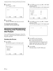
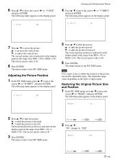
...to increase the horizontal size V: to reduce the horizontal size The horizontal picture size is 00. 5 Press ENTER. The following menu appears on the display panel in the range from MIN (-50) to "PIC SIZE" and press ENTER. The menu returns to "YES". The main menu appears on the display... panel. The PIC SIZE menu appears on the display panel. SE L ECT S E T ENTER E N D MENU 30 (GB) The PIC CONTROL menu items are restored. Resizing and Positioning the Picture You...
...to increase the horizontal size V: to reduce the horizontal size The horizontal picture size is 00. 5 Press ENTER. The following menu appears on the display panel in the range from MIN (-50) to "PIC SIZE" and press ENTER. The menu returns to "YES". The main menu appears on the display... panel. The PIC SIZE menu appears on the display panel. SE L ECT S E T ENTER E N D MENU 30 (GB) The PIC CONTROL menu items are restored. Resizing and Positioning the Picture You...
User Manual
Page 83
...(B) to "H SHIFT" and press ENTER. v: to shift the picture upward V: to shift the picture downward The vertical picture position is indicated on the display panel in the range from MIN (-50) to MAX (+50). Note You cannot resize or adjust the position of input signal. RESET : NO 2 Press v /...S E T ENTER E N D MENU 31 (GB) v: to increase the vertical size V: to reduce the vertical size The vertical picture size is indicated on the display panel in the range from MIN (-50) to MAX (+50). Adjusting the Picture Position 1 In the PIC SIZE menu, press v / V to move the cursor (B) to "V...
...(B) to "H SHIFT" and press ENTER. v: to shift the picture upward V: to shift the picture downward The vertical picture position is indicated on the display panel in the range from MIN (-50) to MAX (+50). Note You cannot resize or adjust the position of input signal. RESET : NO 2 Press v /...S E T ENTER E N D MENU 31 (GB) v: to increase the vertical size V: to reduce the vertical size The vertical picture size is indicated on the display panel in the range from MIN (-50) to MAX (+50). Adjusting the Picture Position 1 In the PIC SIZE menu, press v / V to move the cursor (B) to "V...
User Manual
Page 84
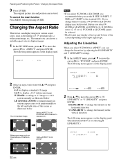
... to move the cursor (B) to a 16:9 screen naturally as the normal 4:3 TV program ratio, a widescreen image, etc. The following menu appears on the display panel. 2 Select an aspect ratio item with v / V and press ENTER. 4×3: to display a standard 4:3 image 16×9: to display a 16:9 widescreen ... illustrated below The 4:3 standard image Setting ASPECT to W ZOOM and both linearities to the left and right sides of the screen depending on the display panel. Setting ASPECT to LB ZOOM ASPECT : W Z OOM H L I NEAR I TY : 00 RESET SE L ECT S E T ENTER E N D MENU 2 Press v ...
... to move the cursor (B) to a 16:9 screen naturally as the normal 4:3 TV program ratio, a widescreen image, etc. The following menu appears on the display panel. 2 Select an aspect ratio item with v / V and press ENTER. 4×3: to display a standard 4:3 image 16×9: to display a 16:9 widescreen ... illustrated below The 4:3 standard image Setting ASPECT to W ZOOM and both linearities to the left and right sides of the screen depending on the display panel. Setting ASPECT to LB ZOOM ASPECT : W Z OOM H L I NEAR I TY : 00 RESET SE L ECT S E T ENTER E N D MENU 2 Press v ...

User Manual
Page 85
3 Adjust the linearity with v / V and press ENTER. The main menu appears on the display panel. The PIC SIZE menu appears on the display panel. The following menu appears on the edges of the characters or the vertical lines, you are adjusting H SIZE, H SHIFT, V SIZE, V SHIFT, H ...LINEARITY or V LINEARITY, the value displayed on the display panel is too much noise on the display panel. Press v / V to move the cursor (B) to "RESET" and press ENTER. Changing the Aspect Ratio / Adjusting the Pixels Adjusting the Pixels...
3 Adjust the linearity with v / V and press ENTER. The main menu appears on the display panel. The PIC SIZE menu appears on the display panel. The following menu appears on the edges of the characters or the vertical lines, you are adjusting H SIZE, H SHIFT, V SIZE, V SHIFT, H ...LINEARITY or V LINEARITY, the value displayed on the display panel is too much noise on the display panel. Press v / V to move the cursor (B) to "RESET" and press ENTER. Changing the Aspect Ratio / Adjusting the Pixels Adjusting the Pixels...

User Manual
Page 86
... the PIC CONTROL and PIC SIZE menus can be restored whenever necessary. Storing the Current Setting 1 Press MENU. The MEMORY menu appears on the display panel. SE L ECT S E T ENTER E N D MENU 2 Press v / V to move the cursor (B) to "MEMORY" and press ENTER. The saved settings can... with v / V and press ENTER. Adjusting automatically (1) Select AUTO with v / V and press ENTER. The following menu appears on the display panel. (The illustration below is for use as the input signal when adjusting the dot phase. • While you are adjusted automatically. You can 't ...
... the PIC CONTROL and PIC SIZE menus can be restored whenever necessary. Storing the Current Setting 1 Press MENU. The MEMORY menu appears on the display panel. SE L ECT S E T ENTER E N D MENU 2 Press v / V to move the cursor (B) to "MEMORY" and press ENTER. The saved settings can... with v / V and press ENTER. Adjusting automatically (1) Select AUTO with v / V and press ENTER. The following menu appears on the display panel. (The illustration below is for use as the input signal when adjusting the dot phase. • While you are adjusted automatically. You can 't ...

User Manual
Page 87
... - Memory number Setting name SAVE / No . 0 1 R G B / fH 3 1 . 5 kHz / fV 5 9 . 9 Hz / P O L [ N / N ] - EMPTY - -" message appears on the display panel. When you finish inputting the name, then press MENU. The selected character is not the same as that of the setting fails, the "SAVE ERROR...you name the setting, follow the steps below. The "SAVE COMPLETED" message appears and flashes for about five seconds. The cursor (B) appears on the display panel. SE L ECT S E T ENTER E N D MENU Character list 7 Select the character to be changed with v / V and press ENTER. 3...
... - Memory number Setting name SAVE / No . 0 1 R G B / fH 3 1 . 5 kHz / fV 5 9 . 9 Hz / P O L [ N / N ] - EMPTY - -" message appears on the display panel. When you finish inputting the name, then press MENU. The selected character is not the same as that of the setting fails, the "SAVE ERROR...you name the setting, follow the steps below. The "SAVE COMPLETED" message appears and flashes for about five seconds. The cursor (B) appears on the display panel. SE L ECT S E T ENTER E N D MENU Character list 7 Select the character to be changed with v / V and press ENTER. 3...
