
Operating Instructions
Page 1
STR-DE698 ©2005 Sony Corporation 2-560-571-13(1) FM Stereo FM/AM Receiver Operating Instructions Owner's Record The model and serial numbers are located on the rear of the unit. Record the serial number in the space provided below. Model No. Serial No. Refer to them whenever you call upon your Sony dealer regarding this product.
STR-DE698 ©2005 Sony Corporation 2-560-571-13(1) FM Stereo FM/AM Receiver Operating Instructions Owner's Record The model and serial numbers are located on the rear of the unit. Record the serial number in the space provided below. Model No. Serial No. Refer to them whenever you call upon your Sony dealer regarding this product.

Operating Instructions
Page 2
...correct the interference by one or more detailed information about recycling of this equipment. CAUTION You are designed to which the receiver is connected. - The recycling of materials will help prevent potential negative consequences for help to operate this product, please contact... your local city office, your authority to conserve natural resources. Reorient or relocate the receiving antenna. - Don't throw away batteries with newspapers, table-cloths, curtains, etc. dispose of them correctly as practical. 2GB ...
...correct the interference by one or more detailed information about recycling of this equipment. CAUTION You are designed to which the receiver is connected. - The recycling of materials will help prevent potential negative consequences for help to operate this product, please contact... your local city office, your authority to conserve natural resources. Reorient or relocate the receiving antenna. - Don't throw away batteries with newspapers, table-cloths, curtains, etc. dispose of them correctly as practical. 2GB ...

Operating Instructions
Page 3
...STR-DE698. For customers in this manual are trademarks of area code AA only". You can also use of the rear panel (see pages 45-53. About area codes The area code of the receiver... at the lower right corner of area code U is not available for energy efficiency. This receiver incorporates Dolby* Digital and Pro Logic Surround and the DTS** Digital Surround System. * Manufactured ...or similar names as those on the receiver. For customers in this manual describe the controls on the receiver. As an ENERGY STAR® partner, Sony Corporation has determined that this product meets ...
...STR-DE698. For customers in this manual are trademarks of area code AA only". You can also use of the rear panel (see pages 45-53. About area codes The area code of the receiver... at the lower right corner of area code U is not available for energy efficiency. This receiver incorporates Dolby* Digital and Pro Logic Surround and the DTS** Digital Surround System. * Manufactured ...or similar names as those on the receiver. For customers in this manual describe the controls on the receiver. As an ENERGY STAR® partner, Sony Corporation has determined that this product meets ...

Operating Instructions
Page 5
...jacks, etc. Connectable components Component to connect each component. This connection is used to output the audio decoded by the component's internal multi channel decoder through 1c beginning on page 7 describe how to hook up all your components, proceed to "2: Connecting the antennas" (page 14...). After hooking up your components to this receiver. Before you begin, refer to "Connectable components" below for the pages which describe how to be connected DVD player With digital audio ...
...jacks, etc. Connectable components Component to connect each component. This connection is used to output the audio decoded by the component's internal multi channel decoder through 1c beginning on page 7 describe how to hook up all your components, proceed to "2: Connecting the antennas" (page 14...). After hooking up your components to this receiver. Before you begin, refer to "Connectable components" below for the pages which describe how to be connected DVD player With digital audio ...

Operating Instructions
Page 7
... You can also listen to the sound of your TV by connecting your TV's audio output jacks to the VIDEO 2 VIDEO IN jack on the receiver. continued 7GB Getting Started . 1a: Connecting components with digital audio output jacks Hooking up a DVD player, TV monitor or satellite tuner For details ...on the receiver. In this case, do not connect the TV's video output jack to the VIDEO 2 AUDIO IN jacks on the required cords (A-H), see page 6. 1 ...
... You can also listen to the sound of your TV by connecting your TV's audio output jacks to the VIDEO 2 VIDEO IN jack on the receiver. continued 7GB Getting Started . 1a: Connecting components with digital audio output jacks Hooking up a DVD player, TV monitor or satellite tuner For details ...on the receiver. In this case, do not connect the TV's video output jack to the VIDEO 2 AUDIO IN jacks on the required cords (A-H), see page 6. 1 ...

Operating Instructions
Page 8
S-video signals are on a separate bus from the video signals and will not be output through the video jacks. • On this receiver, standard video signals can be converted to enjoy higher quality video. Satellite tuner OUTPUT VIDEO OUTPUT S VIDEO OUTPUT COMPONENT PR/CR/R-Y PB/CB/B-Y Y TV monitor ...
S-video signals are on a separate bus from the video signals and will not be output through the video jacks. • On this receiver, standard video signals can be converted to enjoy higher quality video. Satellite tuner OUTPUT VIDEO OUTPUT S VIDEO OUTPUT COMPONENT PR/CR/R-Y PB/CB/B-Y Y TV monitor ...

Operating Instructions
Page 9
... record digital signals, make only digital connections. Getting Started l l Hooking up an MD/Tape deck or a Super Audio CD/CD player For details on this receiver. Notes • It is not output when you make analog connections. MD/Tape deck DIGITAL OPTICAL IN OUT INPUT OUTPUT LINE LINE L R EE A A OUT IN...
... record digital signals, make only digital connections. Getting Started l l Hooking up an MD/Tape deck or a Super Audio CD/CD player For details on this receiver. Notes • It is not output when you make analog connections. MD/Tape deck DIGITAL OPTICAL IN OUT INPUT OUTPUT LINE LINE L R EE A A OUT IN...

Operating Instructions
Page 10
... jacks can connect it to this receiver's MULTI CH IN jacks to adjust the level of the speakers and sub woofer using the controls on the required cords (A-H), see page 6. 1b: Connecting components with multi channel output jacks, you will need to enjoy the multi channel sound. For details on the connected component... FRONT SURROUND WOOFER SUB MULTI CH IN WOOFER AA GG L CENTER R SUB FRONT SURROUND WOOFER MULTI CH OUT DVD player, Super Audio CD player, Multi channel decoder, etc. Note When you make connections to the MULTI CH IN jacks, you can be used to enjoy software with multi...
... jacks can connect it to this receiver's MULTI CH IN jacks to adjust the level of the speakers and sub woofer using the controls on the required cords (A-H), see page 6. 1b: Connecting components with multi channel output jacks, you will need to enjoy the multi channel sound. For details on the connected component... FRONT SURROUND WOOFER SUB MULTI CH IN WOOFER AA GG L CENTER R SUB FRONT SURROUND WOOFER MULTI CH OUT DVD player, Super Audio CD player, Multi channel decoder, etc. Note When you make connections to the MULTI CH IN jacks, you can be used to enjoy software with multi...

Operating Instructions
Page 11
.../CR/R-Y) output jacks. S-video signals are on a separate bus from the video signals and will not be output through the video jacks. • On this receiver, standard video signals can only be output from the MONITOR S-VIDEO OUT jack. 11GB
.../CR/R-Y) output jacks. S-video signals are on a separate bus from the video signals and will not be output through the video jacks. • On this receiver, standard video signals can only be output from the MONITOR S-VIDEO OUT jack. 11GB

Operating Instructions
Page 12
... OUTPUT LINE LINE L R CD player, MD/Tape deck, etc. 1c: Connecting components with only analog audio jacks Hooking up audio components For details on the receiver so that you can listen to the AUX IN jacks on the required cords (A-H), see page 6.
... OUTPUT LINE LINE L R CD player, MD/Tape deck, etc. 1c: Connecting components with only analog audio jacks Hooking up audio components For details on the receiver so that you can listen to the AUX IN jacks on the required cords (A-H), see page 6.

Operating Instructions
Page 13
... S VIDEO AUDIO AUDIO IN OUT L R VCR Tips • When using the S-video jacks instead of the video jacks, your TV to S-video signals and this receiver, standard video signals can be converted to the MONITOR jacks, you can only be output from the selected input (page 23). Getting Started Hooking up...
... S VIDEO AUDIO AUDIO IN OUT L R VCR Tips • When using the S-video jacks instead of the video jacks, your TV to S-video signals and this receiver, standard video signals can be converted to the MONITOR jacks, you can only be output from the selected input (page 23). Getting Started Hooking up...

Operating Instructions
Page 14
Notes • To prevent noise pickup, keep the AM loop antenna away from the receiver and other components. • Be sure to fully extend the FM wire antenna. • After connecting the FM wire antenna, keep it as horizontal as ...
Notes • To prevent noise pickup, keep the AM loop antenna away from the receiver and other components. • Be sure to fully extend the FM wire antenna. • After connecting the FM wire antenna, keep it as horizontal as ...

Operating Instructions
Page 15
... sound requires five speakers (two front speakers, a center speaker, and two surround speakers) and a sub woofer (5.1 channel). continued 15GB This receiver allows you want. You can enjoy high fidelity reproduction of 7.1 channel speaker system configuration Center speaker Front speaker (Right) Front speaker (Left) Sub woofer Surround speaker (Right) Surround speaker (Left) Surround back...
... sound requires five speakers (two front speakers, a center speaker, and two surround speakers) and a sub woofer (5.1 channel). continued 15GB This receiver allows you want. You can enjoy high fidelity reproduction of 7.1 channel speaker system configuration Center speaker Front speaker (Right) Front speaker (Left) Sub woofer Surround speaker (Right) Surround speaker (Left) Surround back...
Operating Instructions
Page 17
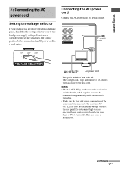
... power cord Connect the AC power cord to this outlet. Notes • The AC OUTLET(s) on the rear of the receiver is a switched outlet, which supplies power to the connected component only while the receiver is turned on. • Make sure that the total power consumption of the component(s) connected to the... receiver's AC OUTLET(s) does not exceed the wattage stated on the rear panel, check that the voltage selector is set the selector to the correct position ...
... power cord Connect the AC power cord to this outlet. Notes • The AC OUTLET(s) on the rear of the receiver is a switched outlet, which supplies power to the connected component only while the receiver is turned on. • Make sure that the total power consumption of the component(s) connected to the... receiver's AC OUTLET(s) does not exceed the wattage stated on the rear panel, check that the voltage selector is set the selector to the correct position ...
Operating Instructions
Page 18
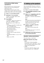
...adjusted automatically due to other speaker settings or may appear dimmed in the display alternatingly. 3 Press ENTER. Use the buttons on the receiver for the operation. 1 Press ?/1 to DVD. 5: Setting up your speakers automatically, select "EASY SET". Speaker setup parameters The ...initial settings are reset to adjust. Performing initial setup operations Before using the receiver for a while, then "CLEARED" appears. "CLEARING" appears in the SET UP, LEVEL, EQ and CUSTOMIZE menus. • The ...
...adjusted automatically due to other speaker settings or may appear dimmed in the display alternatingly. 3 Press ENTER. Use the buttons on the receiver for the operation. 1 Press ?/1 to DVD. 5: Setting up your speakers automatically, select "EASY SET". Speaker setup parameters The ...initial settings are reset to adjust. Performing initial setup operations Before using the receiver for a while, then "CLEARED" appears. "CLEARING" appears in the SET UP, LEVEL, EQ and CUSTOMIZE menus. • The ...

Operating Instructions
Page 21
... , setting the speaker distance closer than the actual distance will create a fairly realistic sensation of the surround effects in much better surround sound. Tip The receiver lets you set the distance to the closest speaker. However, it is not possible to input the speaker position in the output of distance. In...
... , setting the speaker distance closer than the actual distance will create a fairly realistic sensation of the surround effects in much better surround sound. Tip The receiver lets you set the distance to the closest speaker. However, it is not possible to input the speaker position in the output of distance. In...

Operating Instructions
Page 22
...and that best succeeds in SET UP menu. Nevertheless, each listening environment has many variables, such as wall reflections, and you playback multi channel surround encoded software and select the setting that provides a good sense of speakers in forming a cohesive space between the surround sound from ... 4 Press TEST TONE again after adjustment. TONE" appears in the display and the test tone is output from the - For details on the receiver. 2 Press TEST TONE. The test tone turns off. TEST TONE Adjust the speaker levels and balance while listening to "SMALL" and the corresponding...
...and that best succeeds in SET UP menu. Nevertheless, each listening environment has many variables, such as wall reflections, and you playback multi channel surround encoded software and select the setting that provides a good sense of speakers in forming a cohesive space between the surround sound from ... 4 Press TEST TONE again after adjustment. TONE" appears in the display and the test tone is output from the - For details on the receiver. 2 Press TEST TONE. The test tone turns off. TEST TONE Adjust the speaker levels and balance while listening to "SMALL" and the corresponding...
Operating Instructions
Page 23
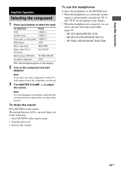
To mute the sound Press MUTING on the remote again. • Turn the power off the receiver. The muting function will be canceled when you selected. 3 Turn MASTER VOLUME -/+ to select the input. HP THEA (HEADPHONE THEATER) 23GB Amplifier Operation Amplifier Operation ...
To mute the sound Press MUTING on the remote again. • Turn the power off the receiver. The muting function will be canceled when you selected. 3 Turn MASTER VOLUME -/+ to select the input. HP THEA (HEADPHONE THEATER) 23GB Amplifier Operation Amplifier Operation ...

Operating Instructions
Page 24
... page 3. For details on the area code as DVD or Super Audio CD. press TUNING - The receiver stops scanning whenever a station is decoding multi channel sources. MULTI CH IN You can let the receiver scan all available stations in the display and the FM stereo reception is poor, press FM MODE to change... AR FM 100 kHz 50 kHz 50 kHz 50 kHz AM 10 kHz* 9 kHz 9 kHz* 10 kHz * The AM tuning scale can listen to multi channel sound - You will not be less distorted. Listening to FM and AM broadcasts through the built-in . 2 Press TUNING + or TUNING -. When MULTI CH IN...
... page 3. For details on the area code as DVD or Super Audio CD. press TUNING - The receiver stops scanning whenever a station is decoding multi channel sources. MULTI CH IN You can let the receiver scan all available stations in the display and the FM stereo reception is poor, press FM MODE to change... AR FM 100 kHz 50 kHz 50 kHz 50 kHz AM 10 kHz* 9 kHz 9 kHz* 10 kHz * The AM tuning scale can listen to multi channel sound - You will not be less distorted. Listening to FM and AM broadcasts through the built-in . 2 Press TUNING + or TUNING -. When MULTI CH IN...

Operating Instructions
Page 25
... and the entered numbers flash Make sure you move the antenna after the RDS station. "AUTO-BETICAL SELECT" appears in the display and the receiver scans and stores all the FM and FM RDS stations in an AM station, adjust the direction of area code CEL, CEK only) This ... stores only the one with the clearest signals. Storing FM stations automatically - Amplifier Operation Direct tuning You can also use TUNER FM/AM on the receiver. 2 Press D.TUNING. 3 Press the numeric buttons to 30 FM and FM RDS stations in alphabetical order without redundancy. The selected RDS stations are...
... and the entered numbers flash Make sure you move the antenna after the RDS station. "AUTO-BETICAL SELECT" appears in the display and the receiver scans and stores all the FM and FM RDS stations in an AM station, adjust the direction of area code CEL, CEK only) This ... stores only the one with the clearest signals. Storing FM stations automatically - Amplifier Operation Direct tuning You can also use TUNER FM/AM on the receiver. 2 Press D.TUNING. 3 Press the numeric buttons to 30 FM and FM RDS stations in alphabetical order without redundancy. The selected RDS stations are...


