
Operating Instructions (HT-7000DH)
Page 8
...components obtained by Pro Logic processing) Example: Recording format (Front/ Surround): 3/2.1 Sound Field: A.F.D. The letters (L, C, R, etc.) indicate the channels being input through the OPTICAL jack, or when INPUT MODE is set to "OPT IN" (page 64). AUTO SW LCR SL SR 8US The boxes around the letters vary to... "AUTO" and the source signal is a digital signal being played back. Lights up when INPUT MODE is set to show how the receiver downmixes the source sound. Name M OPT N SLEEP O Playback channel indicators L R C SL SR S Function Lights up when the sleep timer is activated ...
...components obtained by Pro Logic processing) Example: Recording format (Front/ Surround): 3/2.1 Sound Field: A.F.D. The letters (L, C, R, etc.) indicate the channels being input through the OPTICAL jack, or when INPUT MODE is set to "OPT IN" (page 64). AUTO SW LCR SL SR 8US The boxes around the letters vary to... "AUTO" and the source signal is a digital signal being played back. Lights up when INPUT MODE is set to show how the receiver downmixes the source sound. Name M OPT N SLEEP O Playback channel indicators L R C SL SR S Function Lights up when the sleep timer is activated ...
Operating Instructions (HT-7000DH)
Page 9
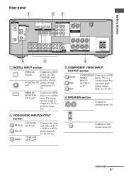
... to speakers (page 16). D SPEAKER section Connects to a DVD IN jack player, etc. continued 9US Getting Started Rear panel 1 23 DIGITAL OPTICAL VIDEO 1 IN VIDEO 2 IN ANTENNA XM AM DVD IN VIDEO 2 IN MONITOR OUT COMPONENT VIDEO ASSIGNABLE Y ASSIGNABLE HDMI MONITOR PB/CB /B-Y VIDEO IN VIDEO IN ...
... to speakers (page 16). D SPEAKER section Connects to a DVD IN jack player, etc. continued 9US Getting Started Rear panel 1 23 DIGITAL OPTICAL VIDEO 1 IN VIDEO 2 IN ANTENNA XM AM DVD IN VIDEO 2 IN MONITOR OUT COMPONENT VIDEO ASSIGNABLE Y ASSIGNABLE HDMI MONITOR PB/CB /B-Y VIDEO IN VIDEO IN ...

Operating Instructions (HT-7000DH)
Page 19
Note When you make connections to the MULTI CH IN jacks, you can be used to connect an external multi channel decoder. A B DIGITAL OPTICAL VIDEO 1 IN VIDEO 2 IN ANTENNA XM AM DVD IN VIDEO 2 IN MONITOR OUT COMPONENT VIDEO ASSIGNABLE Y ASSIGNABLE HDMI MONITOR PB/CB /B-Y VIDEO IN VIDEO IN ... jacks If your DVD or Super Audio CD player is equipped with multi channel output jacks, you will need to adjust the level of this receiver to enjoy multi channel sound.
Note When you make connections to the MULTI CH IN jacks, you can be used to connect an external multi channel decoder. A B DIGITAL OPTICAL VIDEO 1 IN VIDEO 2 IN ANTENNA XM AM DVD IN VIDEO 2 IN MONITOR OUT COMPONENT VIDEO ASSIGNABLE Y ASSIGNABLE HDMI MONITOR PB/CB /B-Y VIDEO IN VIDEO IN ... jacks If your DVD or Super Audio CD player is equipped with multi channel output jacks, you will need to adjust the level of this receiver to enjoy multi channel sound.

Operating Instructions (HT-7000DH)
Page 20
Super Audio CD player/ CD player MD deck/ Tape deck A A DIGITAL OPTICAL VIDEO 1 IN VIDEO 2 IN ANTENNA XM AM DVD IN VIDEO 2 IN MONITOR OUT COMPONENT VIDEO ASSIGNABLE Y ASSIGNABLE HDMI MONITOR PB/CB /B-Y VIDEO IN VIDEO IN ...
Super Audio CD player/ CD player MD deck/ Tape deck A A DIGITAL OPTICAL VIDEO 1 IN VIDEO 2 IN ANTENNA XM AM DVD IN VIDEO 2 IN MONITOR OUT COMPONENT VIDEO ASSIGNABLE Y ASSIGNABLE HDMI MONITOR PB/CB /B-Y VIDEO IN VIDEO IN ...

Operating Instructions (HT-7000DH)
Page 22
...components such as a TV monitor or a projector to the MONITOR OUT jack on the receiver. • Turn on the receiver when the video and audio of a playback component are being output to the jacks of the receiver is not turned on a TV screen. Connect video cords according to a TV via...connect the MONITOR OUT jack to this receiver can be displayed on , neither video nor audio is not necessary to connect all the cables. Hooking up a TV monitor The image from a visual component connected to a TV monitor. It is transmitted. TV monitor A B DIGITAL OPTICAL VIDEO 1 IN VIDEO 2 IN ANTENNA...
...components such as a TV monitor or a projector to the MONITOR OUT jack on the receiver. • Turn on the receiver when the video and audio of a playback component are being output to the jacks of the receiver is not turned on a TV screen. Connect video cords according to a TV via...connect the MONITOR OUT jack to this receiver can be displayed on , neither video nor audio is not necessary to connect all the cables. Hooking up a TV monitor The image from a visual component connected to a TV monitor. It is transmitted. TV monitor A B DIGITAL OPTICAL VIDEO 1 IN VIDEO 2 IN ANTENNA...

Operating Instructions (HT-7000DH)
Page 23
... Refer to connect all the cables. SPEAKERS L L + - + - R SURROUND SPEAKERS R FRONT A A Coaxial digital cord (supplied) B Audio cord (not supplied) C Optical digital cord (not supplied) continued 23US Tip All the digital audio jacks are compatible with the DVD player. • When connecting... multi channel digital audio from the DVD player, set the digital audio output setting on the DVD player. DVD recorder A B C B DIGITAL OPTICAL VIDEO 1 IN VIDEO 2 IN ANTENNA XM AM DVD IN VIDEO 2 IN MONITOR OUT COMPONENT VIDEO ASSIGNABLE Y ASSIGNABLE HDMI MONITOR PB/CB /B-Y ...
... Refer to connect all the cables. SPEAKERS L L + - + - R SURROUND SPEAKERS R FRONT A A Coaxial digital cord (supplied) B Audio cord (not supplied) C Optical digital cord (not supplied) continued 23US Tip All the digital audio jacks are compatible with the DVD player. • When connecting... multi channel digital audio from the DVD player, set the digital audio output setting on the DVD player. DVD recorder A B C B DIGITAL OPTICAL VIDEO 1 IN VIDEO 2 IN ANTENNA XM AM DVD IN VIDEO 2 IN MONITOR OUT COMPONENT VIDEO ASSIGNABLE Y ASSIGNABLE HDMI MONITOR PB/CB /B-Y ...

Operating Instructions (HT-7000DH)
Page 24
...rename the VIDEO 1 input so that you connect a DVD recorder • Be sure to change the factory setting of the VIDEO 1 input button on the receiver's display. R SURROUND SPEAKERS R FRONT A A DVD recorder A Video cord (not supplied) B Component video cord (not supplied) If you can be ...displayed on the remote so that it can use the button to control your DVD recorder. 2 Connecting video DVD player A B DIGITAL OPTICAL VIDEO 1 IN VIDEO 2 IN ANTENNA XM AM DVD IN VIDEO 2 IN MONITOR OUT COMPONENT VIDEO ASSIGNABLE Y ASSIGNABLE HDMI MONITOR PB/CB /B-Y VIDEO...
...rename the VIDEO 1 input so that you connect a DVD recorder • Be sure to change the factory setting of the VIDEO 1 input button on the receiver's display. R SURROUND SPEAKERS R FRONT A A DVD recorder A Video cord (not supplied) B Component video cord (not supplied) If you can be ...displayed on the remote so that it can use the button to control your DVD recorder. 2 Connecting video DVD player A B DIGITAL OPTICAL VIDEO 1 IN VIDEO 2 IN ANTENNA XM AM DVD IN VIDEO 2 IN MONITOR OUT COMPONENT VIDEO ASSIGNABLE Y ASSIGNABLE HDMI MONITOR PB/CB /B-Y VIDEO...

Operating Instructions (HT-7000DH)
Page 25
The sound is output from the supplied speakers and to the receiver. - A A A DIGITAL OPTICAL VIDEO 1 IN VIDEO 2 IN ANTENNA XM AM DVD IN VIDEO 2 IN MONITOR OUT COMPONENT VIDEO ASSIGNABLE Y ASSIGNABLE HDMI MONITOR PB/CB /B-Y VIDEO IN VIDEO IN...the sound does not come out of a component connected via the receiver. R SURROUND SPEAKERS R FRONT A A HDMI cable (not supplied) We recommend that you use a Sony HDMI cable. connect the digital audio jacks on the receiver when the video and audio of the receiver is not turned on, neither video nor audio is transmitted. •...
The sound is output from the supplied speakers and to the receiver. - A A A DIGITAL OPTICAL VIDEO 1 IN VIDEO 2 IN ANTENNA XM AM DVD IN VIDEO 2 IN MONITOR OUT COMPONENT VIDEO ASSIGNABLE Y ASSIGNABLE HDMI MONITOR PB/CB /B-Y VIDEO IN VIDEO IN...the sound does not come out of a component connected via the receiver. R SURROUND SPEAKERS R FRONT A A HDMI cable (not supplied) We recommend that you use a Sony HDMI cable. connect the digital audio jacks on the receiver when the video and audio of the receiver is not turned on, neither video nor audio is transmitted. •...

Operating Instructions (HT-7000DH)
Page 26
...OUT AUDIO IN DVD VIDEO 2 VIDEO 1 L AUDIO CENTER OUT R SUB FRONT SURROUND WOOFER SUB MULTI CH IN WOOFER CENTER + - Notes • When connecting optical digital cords, insert the plugs straight in until they click into place. • Do not bend or tie... optical digital cords. R SURROUND SPEAKERS R FRONT A A Audio cord (not supplied) B Optical digital cord (not supplied) C Video cord (not supplied) D Component video cord (not supplied) 26US Connect audio and video cords according to ...
...OUT AUDIO IN DVD VIDEO 2 VIDEO 1 L AUDIO CENTER OUT R SUB FRONT SURROUND WOOFER SUB MULTI CH IN WOOFER CENTER + - Notes • When connecting optical digital cords, insert the plugs straight in until they click into place. • Do not bend or tie... optical digital cords. R SURROUND SPEAKERS R FRONT A A Audio cord (not supplied) B Optical digital cord (not supplied) C Video cord (not supplied) D Component video cord (not supplied) 26US Connect audio and video cords according to ...

Operating Instructions (HT-7000DH)
Page 27
... components with analog video and audio jack The following illustration shows how to connect a component which has analog jacks such as a VCR, etc. VCR A DIGITAL OPTICAL VIDEO 1 IN VIDEO 2 IN ANTENNA XM AM DVD IN VIDEO 2 IN MONITOR OUT COMPONENT VIDEO ASSIGNABLE Y ASSIGNABLE HDMI MONITOR PB/CB /B-Y VIDEO IN VIDEO IN...
... components with analog video and audio jack The following illustration shows how to connect a component which has analog jacks such as a VCR, etc. VCR A DIGITAL OPTICAL VIDEO 1 IN VIDEO 2 IN ANTENNA XM AM DVD IN VIDEO 2 IN MONITOR OUT COMPONENT VIDEO ASSIGNABLE Y ASSIGNABLE HDMI MONITOR PB/CB /B-Y VIDEO IN VIDEO IN...

Operating Instructions (HT-7000DH)
Page 28
... A * The shape of the connector varies depending on the area code of this receiver. 4: Connecting the antennas Connect the supplied AM loop antenna and FM wire antenna. FM wire antenna (supplied) AM loop antenna (supplied) DIGITAL OPTICAL VIDEO 1 IN VIDEO 2 IN ANTENNA XM AM DVD IN VIDEO 2 IN MONITOR ...SUB FRONT SURROUND WOOFER SUB MULTI CH IN WOOFER CENTER + - Notes • To prevent noise pickup, keep the AM loop antenna away from the receiver and other components. • Be sure to fully extend the FM wire antenna. • After connecting the FM wire antenna, keep it as ...
... A * The shape of the connector varies depending on the area code of this receiver. 4: Connecting the antennas Connect the supplied AM loop antenna and FM wire antenna. FM wire antenna (supplied) AM loop antenna (supplied) DIGITAL OPTICAL VIDEO 1 IN VIDEO 2 IN ANTENNA XM AM DVD IN VIDEO 2 IN MONITOR ...SUB FRONT SURROUND WOOFER SUB MULTI CH IN WOOFER CENTER + - Notes • To prevent noise pickup, keep the AM loop antenna away from the receiver and other components. • Be sure to fully extend the FM wire antenna. • After connecting the FM wire antenna, keep it as ...

Operating Instructions (HT-7000DH)
Page 58
...MD/TAPE SA-CD/CD TUNER AUX MULTI CH 1 2 2CH A.F.D. to select channel 0. 3 Check the XM Radio ID on the receiver to select "AUTO T.", and then turn TUNING +/- XM jack DIGITAL DVD OPTICAL VIDEO 1 IN ANTENNA XM A VIDEO 2 IN AM DVD IN COAXIAL L L R IN SA-CD/CD R OUT IN MD/TAPE... Note To ensure optional reception of XM's satellite signal, move your antenna to various window locations around your home to see where the best reception will be received. Most ...
...MD/TAPE SA-CD/CD TUNER AUX MULTI CH 1 2 2CH A.F.D. to select channel 0. 3 Check the XM Radio ID on the receiver to select "AUTO T.", and then turn TUNING +/- XM jack DIGITAL DVD OPTICAL VIDEO 1 IN ANTENNA XM A VIDEO 2 IN AM DVD IN COAXIAL L L R IN SA-CD/CD R OUT IN MD/TAPE... Note To ensure optional reception of XM's satellite signal, move your antenna to various window locations around your home to see where the best reception will be received. Most ...

Operating Instructions (HT-7000DH)
Page 64
... video input you connect components to both digital and analog connections. Note Some audio input modes may not be set up depending on the receiver to select the audio input mode. V. Other Operations Switching the audio input mode (INPUT MODE) You can select the audio input mode ...COAX IN Specifies the digital audio signals input to the DIGITAL COAXIAL jack. • OPT IN Specifies the digital audio signals input to the DIGITAL OPTICAL jack. • ANALOG Specifies the analog audio signals input to the AUDIO IN (L/R) jacks. You can reassign a component video input to select the...
... video input you connect components to both digital and analog connections. Note Some audio input modes may not be set up depending on the receiver to select the audio input mode. V. Other Operations Switching the audio input mode (INPUT MODE) You can select the audio input mode ...COAX IN Specifies the digital audio signals input to the DIGITAL COAXIAL jack. • OPT IN Specifies the digital audio signals input to the DIGITAL OPTICAL jack. • ANALOG Specifies the analog audio signals input to the AUDIO IN (L/R) jacks. You can reassign a component video input to select the...

Operating Instructions (HT-7000DH)
Page 75
... the MULTI CH IN function is (are fully inserted into the jacks on the receiver has been activated. There is no sound from a specific component. • Check that the component is output from COAXIAL or OPTICAL input jack). • Check that you have connected to both the L and ...R jacks of the following difficulties while using the receiver, use this troubleshooting guide to help you remedy the problem. Use an audio cord...
... the MULTI CH IN function is (are fully inserted into the jacks on the receiver has been activated. There is no sound from a specific component. • Check that the component is output from COAXIAL or OPTICAL input jack). • Check that you have connected to both the L and ...R jacks of the following difficulties while using the receiver, use this troubleshooting guide to help you remedy the problem. Use an audio cord...

Operating Instructions (HT-7000DH)
Page 79
After tuning in any AM station, turn off the receiver. To reset the scale to 9 kHz or 10 kHz. Outputs (Analog) MD/TAPE (OUT), VIDEO 1 (AUDIO OUT) SUB WOOFER Voltage: 800 mV Impedance: 10 kohms ... 7/8 × 6 2/8 × 12 4/8 inches) including projecting parts and controls Mass (Approx.) 8.0 kg (17 lb 11 oz) Additional Information continued 79US Inputs (Digital) DVD (Coaxial) VIDEO 1, 2 (Optical) Sensitivity: -
After tuning in any AM station, turn off the receiver. To reset the scale to 9 kHz or 10 kHz. Outputs (Analog) MD/TAPE (OUT), VIDEO 1 (AUDIO OUT) SUB WOOFER Voltage: 800 mV Impedance: 10 kohms ... 7/8 × 6 2/8 × 12 4/8 inches) including projecting parts and controls Mass (Approx.) 8.0 kg (17 lb 11 oz) Additional Information continued 79US Inputs (Digital) DVD (Coaxial) VIDEO 1, 2 (Optical) Sensitivity: -


