Service Manual
Page 1
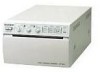
VIDEO GRAPHIC PRINTER UP-895 UP-895CE UP-895MD SERVICE MANUAL 1st Edition
VIDEO GRAPHIC PRINTER UP-895 UP-895CE UP-895MD SERVICE MANUAL 1st Edition

Service Manual
Page 3
... 3-3 4. Initialization of Thermal Head 2-4 2-4. Trap Filter Circuit 4-3 4-1-2. Reading the Serial Data from Frame Memory to Line Memory 4-5 4-3-4. Thermal Head Control and One-Line Memory 4-5 UP-895/(E) 1 Removal of Mechanical Block 2-2 2-3-2. Head Voltage Adjustment 3-3 3-5. nC-SYNC Generator Circuit 4-3 4-1-3. AGC Circuit 4-3 4-1-4. Removal of Switching Regulator 2-3 2-3-4. Tightening the Screws 2-5 2-5. Electrical Alignment 3-1. Circuit Operation Description...
... 3-3 4. Initialization of Thermal Head 2-4 2-4. Trap Filter Circuit 4-3 4-1-2. Reading the Serial Data from Frame Memory to Line Memory 4-5 4-3-4. Thermal Head Control and One-Line Memory 4-5 UP-895/(E) 1 Removal of Mechanical Block 2-2 2-3-2. Head Voltage Adjustment 3-3 3-5. nC-SYNC Generator Circuit 4-3 4-1-3. AGC Circuit 4-3 4-1-4. Removal of Switching Regulator 2-3 2-3-4. Tightening the Screws 2-5 2-5. Electrical Alignment 3-1. Circuit Operation Description...
Service Manual
Page 4
... of Head Temperature Sensor 4-11 4-4-8. Structure 4-14 4-5-2. Print is Out of Order 5-5 5-6. Service Mode (Self-diagnostic Function) 6-1 Printing the Test Pattern 6-1 6-2. Semiconductor Pin Assignments 2 UP-895/(E) Head Up and Down Control 4-10 4-4-5. Monitor of Video Signal to be Input 4-13 4-4-13. Remote Interface 4-13 4-4-14. Basic Operation 4-15 4-5-3. Stair Generation 4-15...
... of Head Temperature Sensor 4-11 4-4-8. Structure 4-14 4-5-2. Print is Out of Order 5-5 5-6. Service Mode (Self-diagnostic Function) 6-1 Printing the Test Pattern 6-1 6-2. Semiconductor Pin Assignments 2 UP-895/(E) Head Up and Down Control 4-10 4-4-5. Monitor of Video Signal to be Input 4-13 4-4-13. Remote Interface 4-13 4-4-14. Basic Operation 4-15 4-5-3. Stair Generation 4-15...
Service Manual
Page 5
Block Diagram Overall ...9-1 10. Schematic Diagrams and Board Layouts FRAME ...10-2 KY-454 ...10-2 SE-531 ...10-2 SE-532 ...10-2 SU-52 ...10-2 MA-99 ...10-4 UP-895/(E) 3 Electrical Parts List 8-7 9. Notes on Repair Parts 8-1 8-2. Spare Parts 8-1. Exploded Views 8-2 8-3. 8.
Block Diagram Overall ...9-1 10. Schematic Diagrams and Board Layouts FRAME ...10-2 KY-454 ...10-2 SE-531 ...10-2 SE-532 ...10-2 SU-52 ...10-2 MA-99 ...10-4 UP-895/(E) 3 Electrical Parts List 8-7 9. Notes on Repair Parts 8-1 8-2. Spare Parts 8-1. Exploded Views 8-2 8-3. 8.

Service Manual
Page 7
UP-895/(E) 3-868-286-01 (1) Video Graphic Printer Instructions for Use Page 20 GB Section 1 Operating Instructions This section is extracted from operation manual. (For UP-895MD/895CE) UP-895 UP-895MD UP-895CE © 1999 Sony Corporation 1-1
UP-895/(E) 3-868-286-01 (1) Video Graphic Printer Instructions for Use Page 20 GB Section 1 Operating Instructions This section is extracted from operation manual. (For UP-895MD/895CE) UP-895 UP-895MD UP-895CE © 1999 Sony Corporation 1-1
Service Manual
Page 8
...27 Making Printouts 27 Selecting the Printing Direction/Image Size ...... 28 Adjusting the Contrast and Brightness 30 Remotely Controlling the Printer 30 Others Precautions 31 Maintenance 31 Specifications 32 Troubleshooting 34 Location and Function of important operating and maintenance (servicing) instructions...system ground unless it may cause harmful interference to the presence of Parts 35 Front 35 Back 36 Overview Introduction The UP-895/895MD/895CE is used in the literature accompanying the appliance. Clear, consistent print quality • High definition, 12.8 ...
...27 Making Printouts 27 Selecting the Printing Direction/Image Size ...... 28 Adjusting the Contrast and Brightness 30 Remotely Controlling the Printer 30 Others Precautions 31 Maintenance 31 Specifications 32 Troubleshooting 34 Location and Function of important operating and maintenance (servicing) instructions...system ground unless it may cause harmful interference to the presence of Parts 35 Front 35 Back 36 Overview Introduction The UP-895/895MD/895CE is used in the literature accompanying the appliance. Clear, consistent print quality • High definition, 12.8 ...
Service Manual
Page 9
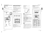
... printout quality. • DIP switches on the Paper Tray The factory settings are as a small screwdriver. WIDE 1 THRU OFF - 1-3 UP-895/(E) Preparation Connection/Setting Up the Printer Connection Notes • Turn off the power to each tone. qa qs DIP SW UP DOWN 1 2 3 4 5 6 7 8 9... connections. • Connect the AC power cord last. Video equipment to video output connector Color/black and white video monitor Setting Up the Printer You can set the printer to change the DIP switch settings Use a small pointed tool such as follows. 1 2 3 4 5 6 7 8 9 q; C PAPER ...
... printout quality. • DIP switches on the Paper Tray The factory settings are as a small screwdriver. WIDE 1 THRU OFF - 1-3 UP-895/(E) Preparation Connection/Setting Up the Printer Connection Notes • Turn off the power to each tone. qa qs DIP SW UP DOWN 1 2 3 4 5 6 7 8 9... connections. • Connect the AC power cord last. Video equipment to video output connector Color/black and white video monitor Setting Up the Printer You can set the printer to change the DIP switch settings Use a small pointed tool such as follows. 1 2 3 4 5 6 7 8 9 q; C PAPER ...
Service Manual
Page 10
... image in helping to save paper by feeding only a short length of paper after being thrown), the printout may also cause malfunction of the printer. Use of another printed surface. Do not store printouts in direct sunlight or other video equipment is to feed the paper manually using the FEED...paper as specified for the UP-880/890MD/890CE. You cannot use double-sided adhesive tape or water-based glue. 24 Preparation Preparation 25 UP-895/(E) Storage of your printouts on the standard screen size of the video monitor. If you have to be poorer but you press the PRINT ...
... image in helping to save paper by feeding only a short length of paper after being thrown), the printout may also cause malfunction of the printer. Use of another printed surface. Do not store printouts in direct sunlight or other video equipment is to feed the paper manually using the FEED...paper as specified for the UP-880/890MD/890CE. You cannot use double-sided adhesive tape or water-based glue. 24 Preparation Preparation 25 UP-895/(E) Storage of your printouts on the standard screen size of the video monitor. If you have to be poorer but you press the PRINT ...
Service Manual
Page 11
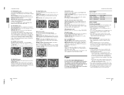
...or FEED button while printing. Do not pull out the paper manually. 26 Preparation Printing Before making printouts Confirm the following . 1-5 UP-895/(E) Preparation Loading Paper Loading Paper Notes • Before loading paper, read "Paper" on page 26) 2 Select the printing direction and ...the EMPTY lamp blinks for a few seconds. Storing printouts • Avoid storing printouts in direct sunlight or other bright places. - The printer starts printing after blinking for this occur, change DIP Switch 4 (MEMORY) to FIELD (SW-UP). (See page 24.) The printout ...
...or FEED button while printing. Do not pull out the paper manually. 26 Preparation Printing Before making printouts Confirm the following . 1-5 UP-895/(E) Preparation Loading Paper Loading Paper Notes • Before loading paper, read "Paper" on page 26) 2 Select the printing direction and ...the EMPTY lamp blinks for a few seconds. Storing printouts • Avoid storing printouts in direct sunlight or other bright places. - The printer starts printing after blinking for this occur, change DIP Switch 4 (MEMORY) to FIELD (SW-UP). (See page 24.) The printout ...
Service Manual
Page 12
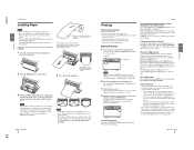
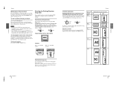
The printer makes a copy of the last printout Press the COPY button. To copy in different directions and sizes You can copy the last printout in ...(See this page.) Notes • If you have pressed the PRINT button only once, the alarm buzzer will sound and the printer will sound as the one displayed in the printer's memory until you press the COPY button, a short buzzer sounds. The image of the STD/SIDE selector and image size selectors... SMALL mode, if you press the COPY button after you press the COPY button immediately after it has been enlarged twice. Operation 29 UP-895/(E)
The printer makes a copy of the last printout Press the COPY button. To copy in different directions and sizes You can copy the last printout in ...(See this page.) Notes • If you have pressed the PRINT button only once, the alarm buzzer will sound and the printer will sound as the one displayed in the printer's memory until you press the COPY button, a short buzzer sounds. The image of the STD/SIDE selector and image size selectors... SMALL mode, if you press the COPY button after you press the COPY button immediately after it has been enlarged twice. Operation 29 UP-895/(E)
Service Manual
Page 13
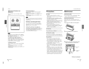
..., such as it is THRU, you will not be sure to reset DIP Switch 8 to next page c Others 31 Others 1-7 UP-895/(E) Operation Printing Adjusting the Contrast and Brightness You can adjust the brightness of printouts using the BRIGHT control. CONTR BRIGHT To adjust the brightness ... cold room to a warm room or when it is set to EE (SW-UP). To adjust the contrast You can remotely control the printer using the CONTR control. To make the contrast stronger, turn the CONTR control counterclockwise. 30 Operation Precautions/Maintenance Precautions Maintenance On safety • ...
..., such as it is THRU, you will not be sure to reset DIP Switch 8 to next page c Others 31 Others 1-7 UP-895/(E) Operation Printing Adjusting the Contrast and Brightness You can adjust the brightness of printouts using the BRIGHT control. CONTR BRIGHT To adjust the brightness ... cold room to a warm room or when it is set to EE (SW-UP). To adjust the contrast You can remotely control the printer using the CONTR control. To make the contrast stronger, turn the CONTR control counterclockwise. 30 Operation Precautions/Maintenance Precautions Maintenance On safety • ...
Service Manual
Page 14
...;F) Operating humidity 20 % to 80 % (no condensation allowed) Protection against electric shock Class I Protection against harmful ingress of water Ordinary Degree of safety in the printer. • Clean the head only when necessary. Notes • Do not press the PRINT or COPY button while the cleaning sheet is completed. 6 Press the... the door by pushing it. 5 Press the FEED button and keep it may cause a malfunction. If you clean the head too often, it pressed. UP-895/(E) 1-8 Others Maintenance/Specifications 4 Close the door by pushing it.
...;F) Operating humidity 20 % to 80 % (no condensation allowed) Protection against electric shock Class I Protection against harmful ingress of water Ordinary Degree of safety in the printer. • Clean the head only when necessary. Notes • Do not press the PRINT or COPY button while the cleaning sheet is completed. 6 Press the... the door by pushing it. 5 Press the FEED button and keep it may cause a malfunction. If you clean the head too often, it pressed. UP-895/(E) 1-8 Others Maintenance/Specifications 4 Close the door by pushing it.
Service Manual
Page 15
...guards against heat build-up ? (page 26) This problem may encounter with your Sony dealer or local authorized Sony service facility. qa qs STD NOR SML R/T L/B BOTH SIDE POSI CONTR 2×... 1 Power switch and lamp Turns the power on the first few printouts. 1-9 UP-895/(E) Others Troubleshooting Troubleshooting The following troubleshooting checks will help you correct the most common problems ...you press the PRINT button. Should the problem persist, unplug the printer and contact your printer. In the event of Parts For details, refer to the pages indicated ...
...guards against heat build-up ? (page 26) This problem may encounter with your Sony dealer or local authorized Sony service facility. qa qs STD NOR SML R/T L/B BOTH SIDE POSI CONTR 2×... 1 Power switch and lamp Turns the power on the first few printouts. 1-9 UP-895/(E) Others Troubleshooting Troubleshooting The following troubleshooting checks will help you correct the most common problems ...you press the PRINT button. Should the problem persist, unplug the printer and contact your printer. In the event of Parts For details, refer to the pages indicated ...
Service Manual
Page 16
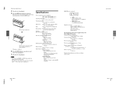
... to a wall outlet using the AC power cord supplied with the unit. qs Paper feeder and cutter Cuts the printing paper. Others 36 Others UP-895/(E) 1-10 Location and Function of the printouts (density gradation). 3 PAPER TYPE switch Selects the paper type. 4 SMOOTHING switch Selects the line density. For detailed information...
... to a wall outlet using the AC power cord supplied with the unit. qs Paper feeder and cutter Cuts the printing paper. Others 36 Others UP-895/(E) 1-10 Location and Function of the printouts (density gradation). 3 PAPER TYPE switch Selects the paper type. 4 SMOOTHING switch Selects the line density. For detailed information...
Service Manual
Page 17
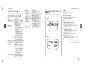
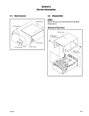
Disassembly n Remove the top cover in the order shown in the figure during removal. Removal of Top Cover 2 Top cover 1 M3 case fixing screw KY-454 board SU-52 board SE-531 board 1 M3 case fixing screw UP-895/(E) 2-1 Board Layout SE-532 board MA-99 board 2-2. Section 2 Service Information 2-1.
Disassembly n Remove the top cover in the order shown in the figure during removal. Removal of Top Cover 2 Top cover 1 M3 case fixing screw KY-454 board SU-52 board SE-531 board 1 M3 case fixing screw UP-895/(E) 2-1 Board Layout SE-532 board MA-99 board 2-2. Section 2 Service Information 2-1.
Service Manual
Page 18
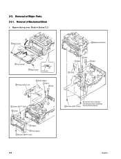
Remove the top cover. (Refer to Section 2-2.) 2 3 Step screw Claws Claws 4 Door panel 3 Step screw 1 Lock arm 6 Power switch rod 5 Rod stopper 1 CN14 1 CN1 3 Mechanical block 1 CN7 1 CN8 1 CN2 1 CN13 1 CN3 1 CN9 2 Screw (BVTT 3x6) 3 Claws 3 Claws 4 Front panel 2 Screws (BVTT 3x6) 2 Screws (BVTT 3x6) Be careful not to slacken the harness when installing the mechanical block. 2-2 UP-895/(E) 2-3. Removal of Mechanical Block 1. Removal of Major Parts 2-3-1.
Remove the top cover. (Refer to Section 2-2.) 2 3 Step screw Claws Claws 4 Door panel 3 Step screw 1 Lock arm 6 Power switch rod 5 Rod stopper 1 CN14 1 CN1 3 Mechanical block 1 CN7 1 CN8 1 CN2 1 CN13 1 CN3 1 CN9 2 Screw (BVTT 3x6) 3 Claws 3 Claws 4 Front panel 2 Screws (BVTT 3x6) 2 Screws (BVTT 3x6) Be careful not to slacken the harness when installing the mechanical block. 2-2 UP-895/(E) 2-3. Removal of Mechanical Block 1. Removal of Major Parts 2-3-1.
Service Manual
Page 19
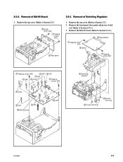
... (M3) 4 CN14 4 CN2 4 CN8 4 CN12 4 CN1 5 Tapping screws (M3) 4 CN13 4 CN7 4 CN3 6 MA-99 board 4 CN9 6 Switching regulator 4 Screws (PS 3x6) 4 Screws (PS 3x6) UP-895/(E) 2-3 Remove the MA-99 board. (Refer to Section 2-3-1.) 3. Remove the top cover. (Refer to Section 2-2.) 2. 2-3-2. Remove the top cover. (Refer to Section 2-2.) 2 Screw (BTP 3x8...
... (M3) 4 CN14 4 CN2 4 CN8 4 CN12 4 CN1 5 Tapping screws (M3) 4 CN13 4 CN7 4 CN3 6 MA-99 board 4 CN9 6 Switching regulator 4 Screws (PS 3x6) 4 Screws (PS 3x6) UP-895/(E) 2-3 Remove the MA-99 board. (Refer to Section 2-3-1.) 3. Remove the top cover. (Refer to Section 2-2.) 2. 2-3-2. Remove the top cover. (Refer to Section 2-2.) 2 Screw (BTP 3x8...
Service Manual
Page 20
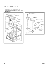
Remove the top cover. (Refer to Section 2-3-1.) 1 Screw (BVTT 3x6) 2 Top chassis 3 Spring compression 5 Head assembly 1 Screw (BVTT 3x6) 4 CN13 4 CN9 2 Screws (PSW 3x6) 3 Heat sink 1 Flat type wire (26 core) Printing side Contact 4 Thermal head 1 Flat type wire (30 core) 2-4 UP-895/(E) Removal of Thermal Head 1. Remove the front panel and power switch rod. (Refer to Section 2-2.) 2. 2-3-4.
Remove the top cover. (Refer to Section 2-3-1.) 1 Screw (BVTT 3x6) 2 Top chassis 3 Spring compression 5 Head assembly 1 Screw (BVTT 3x6) 4 CN13 4 CN9 2 Screws (PSW 3x6) 3 Heat sink 1 Flat type wire (26 core) Printing side Contact 4 Thermal head 1 Flat type wire (30 core) 2-4 UP-895/(E) Removal of Thermal Head 1. Remove the front panel and power switch rod. (Refer to Section 2-2.) 2. 2-3-4.
Service Manual
Page 21
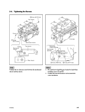
m 1. Tightening the Screws 2 Screw (BVTT 3x6) Top chassis Portion A 1 Screw (BVTT 3x6) Mechanical chassis Push and then fix. Confirm that no clearance exists between the mechanical chassis and top chassis. UP-895/(E) 2-5 Be careful not to hold the gear bracket by hand when installing screws 1 and 2. 2. Mechanical chassis Top chassis Mechanical chassis assembly Gear bracket assembly Front side Belt Rear chassis 1 Screw (PSW 3x6) 2 Screw (BVTT 3x6) n Confirm that the belt tension is not loosened after screw installation. 2-4.
m 1. Tightening the Screws 2 Screw (BVTT 3x6) Top chassis Portion A 1 Screw (BVTT 3x6) Mechanical chassis Push and then fix. Confirm that no clearance exists between the mechanical chassis and top chassis. UP-895/(E) 2-5 Be careful not to hold the gear bracket by hand when installing screws 1 and 2. 2. Mechanical chassis Top chassis Mechanical chassis assembly Gear bracket assembly Front side Belt Rear chassis 1 Screw (PSW 3x6) 2 Screw (BVTT 3x6) n Confirm that the belt tension is not loosened after screw installation. 2-4.
Service Manual
Page 22
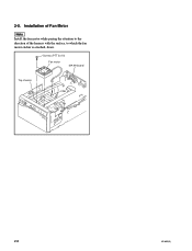
Installation of Fan Motor n Install the fan motor while paying the attention to the direction of the harness with the surface, to which the fan motor sticker is attached, down. Screws (PTT 3x10) Fan motor MA-99 board Top chassis CN6 2-6 UP-895/(E) 2-5.
Installation of Fan Motor n Install the fan motor while paying the attention to the direction of the harness with the surface, to which the fan motor sticker is attached, down. Screws (PTT 3x10) Fan motor MA-99 board Top chassis CN6 2-6 UP-895/(E) 2-5.
