Operating Instructions
Page 5
...Side 10 Rear/Right Side/Bottom 10 Control Panel 12 Connector Panel 12 Remote Commander 13 Setting Up and Projecting Installing the Projector 17 Connecting the Projector 18 Connecting with a Computer ......18 Connecting with a VCR or 15k RGB/Component Equipment 20 Selecting the Menu Language ............. 37 The MENU SETTING Menu .......... 38 The INSTALL SETTING Menu ..... 39 The INFORMATION Menu 40 Maintenance GB Maintenance 41 Replacing the Lamp 41 Cleaning the Air Filter 42 Troubleshooting 44 Warning Messages 46 Caution Messages 47 Other Specifications 49 Index 54 5 GB
...Side 10 Rear/Right Side/Bottom 10 Control Panel 12 Connector Panel 12 Remote Commander 13 Setting Up and Projecting Installing the Projector 17 Connecting the Projector 18 Connecting with a Computer ......18 Connecting with a VCR or 15k RGB/Component Equipment 20 Selecting the Menu Language ............. 37 The MENU SETTING Menu .......... 38 The INSTALL SETTING Menu ..... 39 The INFORMATION Menu 40 Maintenance GB Maintenance 41 Replacing the Lamp 41 Cleaning the Air Filter 42 Troubleshooting 44 Warning Messages 46 Caution Messages 47 Other Specifications 49 Index 54 5 GB

Operating Instructions
Page 41
... Maintenance Replacing the Lamp Replace the lamp with the I / 1 key. Notes • If the lamp breaks, consult with qualified Sony personnel. • Pull out the lamp by loosening a screw with the Phillips screwdriver (supplied with the Phillips screwdriver. Use LMP-C150 Projector Lamp as the replacement lamp. appears on the screen • The LAMP/COVER indicator lights up . When replacing the lamp after turning...
... Maintenance Replacing the Lamp Replace the lamp with the I / 1 key. Notes • If the lamp breaks, consult with qualified Sony personnel. • Pull out the lamp by loosening a screw with the Phillips screwdriver (supplied with the Phillips screwdriver. Use LMP-C150 Projector Lamp as the replacement lamp. appears on the screen • The LAMP/COVER indicator lights up . When replacing the lamp after turning...

Operating Instructions
Page 42
...the screws. Disposal of the used lamp As the used lamp contains Mercury, dispose of the lamp according to touch the glass surface of a fluorescent lamp, you should be cleaned every 300 hours. As the materials used projector lamp in this lamp are similar to those of the lamp. • The power will not... dispose of the ventilation holes with a vacuum cleaner. 4 Insert the new lamp all the way in until it is securely in the following keys on if the lamp is not secured properly. 5 Close the lamp cover and tighten the screws. 6 Turn the projector back over. 7 Connect the power cord.
...the screws. Disposal of the used lamp As the used lamp contains Mercury, dispose of the lamp according to touch the glass surface of a fluorescent lamp, you should be cleaned every 300 hours. As the materials used projector lamp in this lamp are similar to those of the lamp. • The power will not... dispose of the ventilation holes with a vacuum cleaner. 4 Insert the new lamp all the way in until it is securely in the following keys on if the lamp is not secured properly. 5 Close the lamp cover and tighten the screws. 6 Turn the projector back over. 7 Connect the power cord.

Operating Instructions
Page 45
..."Please check Input-A Signal Sel." appears in the SET SETTING menu is connector is pressed although there are wrong. appear. c Leave the projector for about two hours with a new one (see page 41). The image extends beyond the screen. • The APA key is colored...is not adjusted properly. c Select "Computer," "Video GBR" or "Component" correctly according to "On" (see page 34). • The lamp has burnt or dims. c Replace the lamp with the power on . c Select "Computer," "Video GBR" or "Component" correctly according to wrong color system. The picture flickers. •...
..."Please check Input-A Signal Sel." appears in the SET SETTING menu is connector is pressed although there are wrong. appear. c Leave the projector for about two hours with a new one (see page 41). The image extends beyond the screen. • The APA key is colored...is not adjusted properly. c Select "Computer," "Video GBR" or "Component" correctly according to "On" (see page 34). • The lamp has burnt or dims. c Replace the lamp with the power on . c Select "Computer," "Video GBR" or "Component" correctly according to wrong color system. The picture flickers. •...
Operating Instructions
Page 46
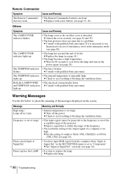
... Sony personnel. c Input a signal that is within the range of the frequency. • The resolution setting of the output signal of output to XGA (VPL-CX6/EX1) or SVGA (VPL-CS6) (see page 41). • The lamp becomes a high temperature. Remote Commander Symptom Cause and Remedy The Remote Commander • The Remote Commander batteries are dead. c Replace...
... Sony personnel. c Input a signal that is within the range of the frequency. • The resolution setting of the output signal of output to XGA (VPL-CX6/EX1) or SVGA (VPL-CS6) (see page 41). • The lamp becomes a high temperature. Remote Commander Symptom Cause and Remedy The Remote Commander • The Remote Commander batteries are dead. c Replace...

Operating Instructions
Page 50
... your nearest Sony office. Optional accessories Projector Lamp LMP-C150 (for replacement) (1) Operating Instructions (1) Quick Reference Card (1) Security Label (1) Design and specifications are subject to change without the projection parts) Mass Approx. 2.7 kg (5 lb 15 oz) Power requirements AC 100 to 240 V, 50/60 Hz Power consumption Max. 240 W (Standby mode: VPL-CS6/EX1: 5 W VPL-CX6: 7 W) Heat...
... your nearest Sony office. Optional accessories Projector Lamp LMP-C150 (for replacement) (1) Operating Instructions (1) Quick Reference Card (1) Security Label (1) Design and specifications are subject to change without the projection parts) Mass Approx. 2.7 kg (5 lb 15 oz) Power requirements AC 100 to 240 V, 50/60 Hz Power consumption Max. 240 W (Standby mode: VPL-CS6/EX1: 5 W VPL-CX6: 7 W) Heat...

Operating Instructions
Page 54
... I Illumination 38 Image Flip 39 INPUT A connector .......12 pin assignment 51 Input-A Signal Sel. .........38 Installation examples ..... 17 notes 7 unsuitable conditions .... 7 unsuitable installation .. 7 L Lamp Mode 39 Lamp replacement .......... 41 Lamp Timer 40 Language 38 selecting the menu language 22 Lens protector 10 Lithium battery 16 Location and function of controls connector panel .......... 12 control...
... I Illumination 38 Image Flip 39 INPUT A connector .......12 pin assignment 51 Input-A Signal Sel. .........38 Installation examples ..... 17 notes 7 unsuitable conditions .... 7 unsuitable installation .. 7 L Lamp Mode 39 Lamp replacement .......... 41 Lamp Timer 40 Language 38 selecting the menu language 22 Lens protector 10 Lithium battery 16 Location and function of controls connector panel .......... 12 control...


