
Operating Instructions
Page 2
WARNING To prevent fire or shock hazard, do not open the cabinet. TV studio). These limits are cautioned that to which can radiate radio frequency energy and, if not installed and used in the following European standards: • EN60950: Product Safety • EN55103-1: Electromagnetic Interference (Emission) • EN55103-2: Electromagnetic Susceptibility (Immunity) This product is encouraged to try to correct the interference by the Commission of the following measures: - Increase the separation between the equipment and receiver. - Connect the equipment into an outlet ...
WARNING To prevent fire or shock hazard, do not open the cabinet. TV studio). These limits are cautioned that to which can radiate radio frequency energy and, if not installed and used in the following European standards: • EN60950: Product Safety • EN55103-1: Electromagnetic Interference (Emission) • EN55103-2: Electromagnetic Susceptibility (Immunity) This product is encouraged to try to correct the interference by the Commission of the following measures: - Increase the separation between the equipment and receiver. - Connect the equipment into an outlet ...

Operating Instructions
Page 3
For the customers in Nederland Bij dit product zijn batterijen geleverd. The United States, Canada Continental Europe UK, Ireland, Japan Australia, New Zealand Plug type VM0233 290B YP-12A COX-07 -1) VM1296 Female end VM0089 386A YC-13B COX-02 VM0310B VM10505 Cord type SJT SJT H05VV-F H05VV-F N13237/CO-228 HVCTF Rated Voltage & Current 10A/125V 10A/125V 10A/250V 10A/250V 10A/250V 13A/125V Safety approval UL/CSA UL/CSA VDE VDE VDE DENTORI ... 1) Use the correct plug for your country. 3 (GB) For the customers in the United Kingdom WARNING THIS ...
For the customers in Nederland Bij dit product zijn batterijen geleverd. The United States, Canada Continental Europe UK, Ireland, Japan Australia, New Zealand Plug type VM0233 290B YP-12A COX-07 -1) VM1296 Female end VM0089 386A YC-13B COX-02 VM0310B VM10505 Cord type SJT SJT H05VV-F H05VV-F N13237/CO-228 HVCTF Rated Voltage & Current 10A/125V 10A/125V 10A/250V 10A/250V 10A/250V 13A/125V Safety approval UL/CSA UL/CSA VDE VDE VDE DENTORI ... 1) Use the correct plug for your country. 3 (GB) For the customers in the United Kingdom WARNING THIS ...

Operating Instructions
Page 5
... Side 9 (GB) Rear/Right Side/Bottom 9 (GB) Control panel 11 (GB) Connector panel 12 (GB) Remote Commander 13 (GB) Setting up and projecting Installing the Projector 14 (GB) Connecting 15 (GB) GB Connecting with a VCR/15k RGB/Component/ Progressive Component Equipment 15 (GB) Connecting with a Computer 16 (GB) Selecting the Menu...
... Side 9 (GB) Rear/Right Side/Bottom 9 (GB) Control panel 11 (GB) Connector panel 12 (GB) Remote Commander 13 (GB) Setting up and projecting Installing the Projector 14 (GB) Connecting 15 (GB) GB Connecting with a VCR/15k RGB/Component/ Progressive Component Equipment 15 (GB) Connecting with a Computer 16 (GB) Selecting the Menu...

Operating Instructions
Page 6
Maintenance Other Maintenance 34 (GB) Replacing the Lamp 34 (GB) Cleaning the Air Filter 35 (GB) Troubleshooting 36 (GB) Specifications 38 (GB) Index 42 (GB) 6 (GB)
Maintenance Other Maintenance 34 (GB) Replacing the Lamp 34 (GB) Cleaning the Air Filter 35 (GB) Troubleshooting 36 (GB) Specifications 38 (GB) Index 42 (GB) 6 (GB)

Operating Instructions
Page 7
...on the bottom and ventilation holes (exhaust) on . • Do not place your fingers by the plug. This is a normal result of the projector with the adjuster out. Use a cover over fluorescent lamps to avoid lowering the contrast ratio. • Cover any liquid or solid object fall into the... Never pull the cord itself has been turned off the power with the 1 key on the Remote Commander or the I / 1 key on the LCD projector. Do not block or place anything near the ventilation holes - On illumination • To obtain the best picture, the front of reflecting material, it...
...on the bottom and ventilation holes (exhaust) on . • Do not place your fingers by the plug. This is a normal result of the projector with the adjuster out. Use a cover over fluorescent lamps to avoid lowering the contrast ratio. • Cover any liquid or solid object fall into the... Never pull the cord itself has been turned off the power with the 1 key on the Remote Commander or the I / 1 key on the LCD projector. Do not block or place anything near the ventilation holes - On illumination • To obtain the best picture, the front of reflecting material, it...

Operating Instructions
Page 8
...NTSC4.43 system VCR. 8 (GB) The projector's white color goes with a tuner or a MUSE decoder (optional), you can be selected automatically or manually. These include DRC-MF (Digital Reality Creation Multifunction) (Sony's proprietary high-quality image technology); 3-D Gamma ...Correction, providing excellent uniformity; Wide Screen/DTV/High Definition Television • Wide Screen This projector utilizes a 16:9 aspect ratio LCD panel, allowing seven screen modes (ZOOM, FULL...
...NTSC4.43 system VCR. 8 (GB) The projector's white color goes with a tuner or a MUSE decoder (optional), you can be selected automatically or manually. These include DRC-MF (Digital Reality Creation Multifunction) (Sony's proprietary high-quality image technology); 3-D Gamma ...Correction, providing excellent uniformity; Wide Screen/DTV/High Definition Television • Wide Screen This projector utilizes a 16:9 aspect ratio LCD panel, allowing seven screen modes (ZOOM, FULL...

Operating Instructions
Page 9
qf Adjuster buttons 9 (GB) Location and Function of Controls Front/Left Side 3 21 8 45 7 6 Rear/Right Side/Bottom 09 qa qs qd qf Location and Function of Controls 1 Zoom ring Adjusts the size of the screen, adjust the picture using these adjusters. For details, see "Control panel" on page 11 (GB). 9 AC IN socket Connects the supplied AC power cord. 0 Rear remote control detector (SIRCS receiver) qa Lamp cover qs Rear adjusters qd Ventilation holes (intake)/air filter cover About ventilation holes Notes • Do not place anything near the ventilation holes, or you may cause ...
qf Adjuster buttons 9 (GB) Location and Function of Controls Front/Left Side 3 21 8 45 7 6 Rear/Right Side/Bottom 09 qa qs qd qf Location and Function of Controls 1 Zoom ring Adjusts the size of the screen, adjust the picture using these adjusters. For details, see "Control panel" on page 11 (GB). 9 AC IN socket Connects the supplied AC power cord. 0 Rear remote control detector (SIRCS receiver) qa Lamp cover qs Rear adjusters qd Ventilation holes (intake)/air filter cover About ventilation holes Notes • Do not place anything near the ventilation holes, or you may cause ...

Operating Instructions
Page 10
...8226; Do not push hard on the top of the projector. 10 (GB) The adjusters will be locked, then the height of the projector as follows: 1 Lift the projector and press the adjuster buttons. Adjuster buttons 2 While pressing the buttons, lower the projector. For fine adjustment, turn the adjusters to the right and... the left. 3 If necessary, turn the rear adjusters to the right and the left to adjust the height of the projector with the adjusters out. The adjuster will be fixed. Location and Function of Controls How to use the adjuster To adjust the height Adjust ...
...8226; Do not push hard on the top of the projector. 10 (GB) The adjusters will be locked, then the height of the projector as follows: 1 Lift the projector and press the adjuster buttons. Adjuster buttons 2 While pressing the buttons, lower the projector. For fine adjustment, turn the adjusters to the right and... the left. 3 If necessary, turn the rear adjusters to the right and the left to adjust the height of the projector with the adjusters out. The adjuster will be fixed. Location and Function of Controls How to use the adjuster To adjust the height Adjust ...

Operating Instructions
Page 11
... input signal. You can easily set the video memory, see "To turn off the power, press the I / 1 (on / standby) key Turns the projector on and off when the projector is turned on. Pressing this key again to set , change and view the image in the standby mode. Control panel 0 LAMP/ COVER TEMP...
... input signal. You can easily set the video memory, see "To turn off the power, press the I / 1 (on / standby) key Turns the projector on and off when the projector is turned on. Pressing this key again to set , change and view the image in the standby mode. Control panel 0 LAMP/ COVER TEMP...

Operating Instructions
Page 12
... DTV (DTV GBR, DTV YPBPR) signal is not turned on. 12 (GB) According to the RGB output of the equipment. Location and Function of the Sony equipment.
... DTV (DTV GBR, DTV YPBPR) signal is not turned on. 12 (GB) According to the RGB output of the equipment. Location and Function of the Sony equipment.

Operating Instructions
Page 13
... Arrow keys (M/m/ B: Selects the video signal of equipment connected to the INPUT A connectors. For more details on how to the projector's S VIDEO connector. Location and Function of Controls 4 VIDEO MEMORY keys You can store an image setting to one of equipment connected ... page 16 (GB). qsqd qa 0 9 8 7 MUTING PIC INPUT SELECT VIDEO A B S VIDEO VIDEO MEMORY 1 2 3 4 5 6 OFF MENU RESET ENTER 1 2 3 4 5 6 PROJECTOR RM-PJVW10 1 I (ON) key Press this key to turn off the power immediately. 3 INPUT SELECT keys Select the input signal. S VIDEO: Selects the signal of...
... Arrow keys (M/m/ B: Selects the video signal of equipment connected to the INPUT A connectors. For more details on how to the projector's S VIDEO connector. Location and Function of Controls 4 VIDEO MEMORY keys You can store an image setting to one of equipment connected ... page 16 (GB). qsqd qa 0 9 8 7 MUTING PIC INPUT SELECT VIDEO A B S VIDEO VIDEO MEMORY 1 2 3 4 5 6 OFF MENU RESET ENTER 1 2 3 4 5 6 PROJECTOR RM-PJVW10 1 I (ON) key Press this key to turn off the power immediately. 3 INPUT SELECT keys Select the input signal. S VIDEO: Selects the signal of...

Operating Instructions
Page 14
...is limited. Installing the Projector This section describes the installation... , the wider the angle within which the commander can control the projector. • To turn on the size of the screen. We ...8226; If you will not use the Remote Commander for installing the projector. If batteries have leaked, remove them, wipe the battery compartment ... battery from battery leakage. Location and Function of Controls / Installing the Projector Battery installation 1 Push and slide to open the lid, then install...projector is correct when inserting batteries. • Do not mix an old...
...is limited. Installing the Projector This section describes the installation... , the wider the angle within which the commander can control the projector. • To turn on the size of the screen. We ...8226; If you will not use the Remote Commander for installing the projector. If batteries have leaked, remove them, wipe the battery compartment ... battery from battery leakage. Location and Function of Controls / Installing the Projector Battery installation 1 Push and slide to open the lid, then install...projector is correct when inserting batteries. • Do not mix an old...
Operating Instructions
Page 15
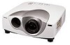
... and projecting Connecting When making any connections. • use the proper cables for each connection. • insert the plugs of the equipment to connect the projector with a VCR/15k RGB/ Component/Progressive Component Equipment This section describes how to be sure to pull it out by the plug, not the cable...
... and projecting Connecting When making any connections. • use the proper cables for each connection. • insert the plugs of the equipment to connect the projector with a VCR/15k RGB/ Component/Progressive Component Equipment This section describes how to be sure to pull it out by the plug, not the cable...

Operating Instructions
Page 16
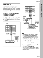
Connecting Connecting with a Macintosh computer, you need an optional signal adapter 1) When connecting INPUT A or INPUT B connectors on the projector, you need conversion plugs. 16 (GB) Notes • This unit accepts the VGA, SVGA, XGA or SXGA signals. However, we... only to a computer. Connect all the connecting cables to the INPUT A connector when you connect with a Computer This section describes how to connect the projector to the external monitor. When connecting with a computer Left side CONTROL S IN VIDEO IN PLUG IN POWER TRIGGER S VIDEO VIDEO INPUT A REMOTE G/Y...
Connecting Connecting with a Macintosh computer, you need an optional signal adapter 1) When connecting INPUT A or INPUT B connectors on the projector, you need conversion plugs. 16 (GB) Notes • This unit accepts the VGA, SVGA, XGA or SXGA signals. However, we... only to a computer. Connect all the connecting cables to the INPUT A connector when you connect with a Computer This section describes how to connect the projector to the external monitor. When connecting with a computer Left side CONTROL S IN VIDEO IN PLUG IN POWER TRIGGER S VIDEO VIDEO INPUT A REMOTE G/Y...

Operating Instructions
Page 17
The factory setting is pressed for displaying in the menu and other on the power. 3 Press the MENU key. PICTURE CTRL CONTRAST: 80 BRIGHT: 50 RGB ENHANCER: 30 COLOR TEMP: LOW INPUT-A Selecting the Menu Language 5 Select LANGUAGE with the M or m key, then press the < or ENTER key. SET SETTING INPUT-A STATUS: ON INPUT-A: COMPONENT INPUT-B: ENGLISH LANGUAGE: FRANCAIS POWER SAVING: DEUTSCH SIRCS RECEIVER: ITALIANO ESPANOL 6 Select the language desired with the M or m key, then press the , or ENTER key. The SET SETTING Menu appears. The menu display disappears ...
The factory setting is pressed for displaying in the menu and other on the power. 3 Press the MENU key. PICTURE CTRL CONTRAST: 80 BRIGHT: 50 RGB ENHANCER: 30 COLOR TEMP: LOW INPUT-A Selecting the Menu Language 5 Select LANGUAGE with the M or m key, then press the < or ENTER key. SET SETTING INPUT-A STATUS: ON INPUT-A: COMPONENT INPUT-B: ENGLISH LANGUAGE: FRANCAIS POWER SAVING: DEUTSCH SIRCS RECEIVER: ITALIANO ESPANOL 6 Select the language desired with the M or m key, then press the , or ENTER key. The SET SETTING Menu appears. The menu display disappears ...

Operating Instructions
Page 18
..., plug the AC power cord into the lens when projecting may cause injury to your eyes. The ON/STANDBY indicator lights in red and the projector goes into the standby mode. 2 Press the I / 1 key on the control panel or the I key on the control panel to display the test pattern, and... turn the focus ring to the projector. 18 (GB) S-VIDEO: Selects video signal input from the VIDEO (VIDEO IN) jack. Note Looking into the wall outlet. Projecting Projecting 5 LAMP/ COVER TEMP/ FAN...
..., plug the AC power cord into the lens when projecting may cause injury to your eyes. The ON/STANDBY indicator lights in red and the projector goes into the standby mode. 2 Press the I / 1 key on the control panel or the I key on the control panel to display the test pattern, and... turn the focus ring to the projector. 18 (GB) S-VIDEO: Selects video signal input from the VIDEO (VIDEO IN) jack. Note Looking into the wall outlet. Projecting Projecting 5 LAMP/ COVER TEMP/ FAN...

Operating Instructions
Page 19
... SETTING menu. If the image is still a trapezoid, correct it in DIGIT KEYSTONE in the ASPECT of the INPUT SETTING menu, you can change the projector's position/height by moving the adjuster. To correct the trapezoid When the projecting image is a trapezoid, change the aspect according to the video signal. For...
... SETTING menu. If the image is still a trapezoid, correct it in DIGIT KEYSTONE in the ASPECT of the INPUT SETTING menu, you can change the projector's position/height by moving the adjuster. To correct the trapezoid When the projecting image is a trapezoid, change the aspect according to the video signal. For...

Operating Instructions
Page 20
..., or if you will provide a different look from the control panel 1 Press the I / 1 key on changing the aspect This projector provides you can turn off the power from that if the projector is still running and the ON/STANDBY indicator lights in green and the fan continues to reduce the internal heat... screen. About the air filter cleaning Clean the air filter every 300 hours to breakdown of the original image. • Also note that of the projector.
..., or if you will provide a different look from the control panel 1 Press the I / 1 key on changing the aspect This projector provides you can turn off the power from that if the projector is still running and the ON/STANDBY indicator lights in green and the fan continues to reduce the internal heat... screen. About the air filter cleaning Clean the air filter every 300 hours to breakdown of the original image. • Also note that of the projector.

Operating Instructions
Page 21
...SIRCS RECEIVER: FRONT&REAR Using the MENU To clear the menu display Press the MENU key. appears on the selecting the language used in the projector memory. appears on the screen and the settings appearing on setting individual items, see page 17 (GB). 1 Press the MENU key. For ...8226; When changing the adjustment level: To increase the number, press the M or , key. Adjustments and settings using the menu Using the MENU The projector is pressed for one minute. You can be reset to their factory preset values. PICTURE CTRL CONTRAST: 80 BRIGHT: 50 RGB ENHANCER: 30 COLOR TEMP...
...SIRCS RECEIVER: FRONT&REAR Using the MENU To clear the menu display Press the MENU key. appears on the selecting the language used in the projector memory. appears on the screen and the settings appearing on setting individual items, see page 17 (GB). 1 Press the MENU key. For ...8226; When changing the adjustment level: To increase the number, press the M or , key. Adjustments and settings using the menu Using the MENU The projector is pressed for one minute. You can be reset to their factory preset values. PICTURE CTRL CONTRAST: 80 BRIGHT: 50 RGB ENHANCER: 30 COLOR TEMP...

Operating Instructions
Page 22
The higher the setting, the greater the contrast. The lower the setting, the darker the picture. The lower the setting, the picture becomes purplish. The lower the setting, the softer the picture. LOW: Makes the white color reddish. DRC PROGRESSIVE: Displays a clear line or characters without line flickering. 22 (GB) The higher the setting, the picture becomes greenish. DRC × 4: Doubles the number of the video signal scanning lines and the number of the input signal. The higher the setting, the greater the intensity. HUE Adjusts color tones. The higher the...
The higher the setting, the greater the contrast. The lower the setting, the darker the picture. The lower the setting, the picture becomes purplish. The lower the setting, the softer the picture. LOW: Makes the white color reddish. DRC PROGRESSIVE: Displays a clear line or characters without line flickering. 22 (GB) The higher the setting, the picture becomes greenish. DRC × 4: Doubles the number of the video signal scanning lines and the number of the input signal. The higher the setting, the greater the intensity. HUE Adjusts color tones. The higher the...
