
Operating Instructions
Page 1
3-876-649-15 (1) Video Projector Operating Instructions VPL-HW10 © 2008 Sony Corporation
3-876-649-15 (1) Video Projector Operating Instructions VPL-HW10 © 2008 Sony Corporation

Operating Instructions
Page 3
For kundene i Norge Dette utstyret kan kobles til et ITstrømfordelingssystem. "Blu-ray Disc" is Sony Deutschland GmbH, Hedelfinger Strasse 61, 70327 Stuttgart, Germany. Disposal of these materials may be disposed of properly. For any service or ...refer to those of a fluorescent lamp, so you should be regulated due to environmental considerations. Disposal of Used Lamp This projector's lamp contains mercury and should dispose of this product is Sony Corporation, 1-7-1 Konan Minato-ku Tokyo, 108-0075 Japan. The Authorized Representative for EMC and product safety is a trademark....
For kundene i Norge Dette utstyret kan kobles til et ITstrømfordelingssystem. "Blu-ray Disc" is Sony Deutschland GmbH, Hedelfinger Strasse 61, 70327 Stuttgart, Germany. Disposal of these materials may be disposed of properly. For any service or ...refer to those of a fluorescent lamp, so you should be regulated due to environmental considerations. Disposal of Used Lamp This projector's lamp contains mercury and should dispose of this product is Sony Corporation, 1-7-1 Konan Minato-ku Tokyo, 108-0075 Japan. The Authorized Representative for EMC and product safety is a trademark....

Operating Instructions
Page 5
... of Controls Front/Right Side 8 Rear/Bottom 9 Remote Control 10 Connections and Preparations Unpacking 11 Step 1: Installing the Projector .........12 Before Setting Up the Projector 12 Positioning the Projector and a screen 14 Step 2: Connecting the Projector .....18 Connecting to a VCR 18 Connecting to a Computer ..........21 Step 3: Adjusting the Picture Position 22 Step 4: Selecting the...
... of Controls Front/Right Side 8 Rear/Bottom 9 Remote Control 10 Connections and Preparations Unpacking 11 Step 1: Installing the Projector .........12 Before Setting Up the Projector 12 Positioning the Projector and a screen 14 Step 2: Connecting the Projector .....18 Connecting to a VCR 18 Connecting to a Computer ..........21 Step 3: Adjusting the Picture Position 22 Step 4: Selecting the...

Operating Instructions
Page 6
Others About the Control for HDMI 54 About the x.v.Color 54 Troubleshooting 55 Warning Indicators 57 Message Lists 58 Replacing the Lamp and the Air Filter and Cleaning the Ventilation Holes (intake 59 Cleaning the Air Filter 62 Fitting the Lens Cap 62 Cleaning and the Screen of the Projector 63 Specifications 64 Preset Signals 66 Input Signals and Adjustable/ Setting Items 69 Ceiling Installation 71 Index 75 6
Others About the Control for HDMI 54 About the x.v.Color 54 Troubleshooting 55 Warning Indicators 57 Message Lists 58 Replacing the Lamp and the Air Filter and Cleaning the Ventilation Holes (intake 59 Cleaning the Air Filter 62 Fitting the Lens Cap 62 Cleaning and the Screen of the Projector 63 Specifications 64 Preset Signals 66 Input Signals and Adjustable/ Setting Items 69 Ceiling Installation 71 Index 75 6

Operating Instructions
Page 7
...operating voltage of your local power supply. • Should any liquid or solid object fall into the lens while the lamp is hot. Caution The projector is equipped with the voltage of your unit is identical with ventilation holes (intake) and ventilation holes (exhaust). On repacking Save the original shipping ... turned off the power with the I/1 (ON/STANDBY) switch, do not disconnect the unit from the wall outlet if it is connected to the projector. The air coming out is on. • Do not place your unit as it is still running. On preventing internal heat buildup After you ...
...operating voltage of your local power supply. • Should any liquid or solid object fall into the lens while the lamp is hot. Caution The projector is equipped with the voltage of your unit is identical with ventilation holes (intake) and ventilation holes (exhaust). On repacking Save the original shipping ... turned off the power with the I/1 (ON/STANDBY) switch, do not disconnect the unit from the wall outlet if it is connected to the projector. The air coming out is on. • Do not place your unit as it is still running. On preventing internal heat buildup After you ...

Operating Instructions
Page 8
Location of Controls Front/Right Side You can use the buttons on the control panel with the same names as those on the remote control to operate the projector. Control panel Lens shift dials (1 page 23) M/m/
Location of Controls Front/Right Side You can use the buttons on the control panel with the same names as those on the remote control to operate the projector. Control panel Lens shift dials (1 page 23) M/m/

Operating Instructions
Page 9
Location of Controls Rear/Bottom Ventilation holes (intake) (1 page 13) Ventilation holes (intake) (1 page 13) Ventilation holes (intake) (1 page 13) Ventilation holes (intake) (1 page 13) Lamp cover (1 page 60) Adjusters (1 page 25) Filter holder (1 page 61) Ventilation holes (intake) (1 page 13) Projector suspension support attaching hole (1 page 71) 9
Location of Controls Rear/Bottom Ventilation holes (intake) (1 page 13) Ventilation holes (intake) (1 page 13) Ventilation holes (intake) (1 page 13) Ventilation holes (intake) (1 page 13) Lamp cover (1 page 60) Adjusters (1 page 25) Filter holder (1 page 61) Ventilation holes (intake) (1 page 13) Projector suspension support attaching hole (1 page 71) 9

Operating Instructions
Page 11
...: • Remote control (1) and Size AA (R6) batteries (2) • AC power cord (1) • Lens cap (1) When you have purchased the projector, the lens cap is put onto the lens. Inserting them forcibly or with care. Unpacking Check the carton to project the picture, etc. Connections and... Preparations Connections and Preparations This section describes how to install the projector and screen, how to connect the equipment from which you want to make sure it . • Do not place the remote in ...
...: • Remote control (1) and Size AA (R6) batteries (2) • AC power cord (1) • Lens cap (1) When you have purchased the projector, the lens cap is put onto the lens. Inserting them forcibly or with care. Unpacking Check the carton to project the picture, etc. Connections and... Preparations Connections and Preparations This section describes how to install the projector and screen, how to connect the equipment from which you want to make sure it . • Do not place the remote in ...

Operating Instructions
Page 12
...dusty and extremely smoky locations Leave space of the sensor may occur. Near a heat or smoke sensor Unsuitable installation Do not place the projector in temperature. Poorly ventilated location Malfunction of more than 30 cm (11 7/8 inches) around the unit. Locations subject to have broader... options for placing the projector and viewing pictures easily. Step 1: Installing the Projector The projector displays pictures output from a VCR or other device. The lens shift allows you to direct cool or warm ...
...dusty and extremely smoky locations Leave space of the sensor may occur. Near a heat or smoke sensor Unsuitable installation Do not place the projector in temperature. Poorly ventilated location Malfunction of more than 30 cm (11 7/8 inches) around the unit. Locations subject to have broader... options for placing the projector and viewing pictures easily. Step 1: Installing the Projector The projector displays pictures output from a VCR or other device. The lens shift allows you to direct cool or warm ...

Operating Instructions
Page 13
... and Preparations Improper use Do not do any of the lamp. Tilting front/rear and left/right 15° or more Avoid using the projector. Installing the projector in such a location may result in the Setup menu to "High" (1 page 47). Blocking the ventilation holes (intake or exhaust) Ventilation holes... or on the location of the ventilation holes (intake or exhaust), see "Location of more 13 Failing to set this mode when using the projector at high altitudes could have adverse effects, such as reducing the reliability of 1,500 m or higher, set "Cooling Setting" in uneven color ...
... and Preparations Improper use Do not do any of the lamp. Tilting front/rear and left/right 15° or more Avoid using the projector. Installing the projector in such a location may result in the Setup menu to "High" (1 page 47). Blocking the ventilation holes (intake or exhaust) Ventilation holes... or on the location of the ventilation holes (intake or exhaust), see "Location of more 13 Failing to set this mode when using the projector at high altitudes could have adverse effects, such as reducing the reliability of 1,500 m or higher, set "Cooling Setting" in uneven color ...

Operating Instructions
Page 14
... within the area indicated in gray in the table on the size of the screen or whether or not you position the projector so that the center of the projector and screen. Screen * ** * Installation position not using lens shift (x = 0, y = 0) ** Example of installation position using lens ...between the center of the screen and the center of the projector's lens. y: Vertical distance between the screen and the front end of the projector's lens. x: Horizontal distance between the center of the screen and the center of the projector on a ceiling, see "Ceiling Installation." (1 page 71)...
... within the area indicated in gray in the table on the size of the screen or whether or not you position the projector so that the center of the projector and screen. Screen * ** * Installation position not using lens shift (x = 0, y = 0) ** Example of installation position using lens ...between the center of the screen and the center of the projector's lens. y: Vertical distance between the screen and the front end of the projector's lens. x: Horizontal distance between the center of the screen and the center of the projector on a ceiling, see "Ceiling Installation." (1 page 71)...

Operating Instructions
Page 17
Top view Screen 3 Project an image on the distance between the screen and the projector or the zooming magnifications. This is parallel to the projector. (1 page 18) Note When using a screen with an uneven surface, stripes pattern may rarely appear on the screen depending on the screen and adjust the picture so that the lens is not a malfunction of the projector. 17 Connections and Preparations 2 Position the projector so that it fits the screen. (1 page 22) To project an image, connect video equipment to the screen.
Top view Screen 3 Project an image on the distance between the screen and the projector or the zooming magnifications. This is parallel to the projector. (1 page 18) Note When using a screen with an uneven surface, stripes pattern may rarely appear on the screen depending on the screen and adjust the picture so that the lens is not a malfunction of the projector. 17 Connections and Preparations 2 Position the projector so that it fits the screen. (1 page 22) To project an image, connect video equipment to the screen.

Operating Instructions
Page 18
poor connection at the plugs may cause a malfunction or poor picture quality. Step 2: Connecting the Projector When making connections, be sure to pull it out from the plug, not the cable itself. • Refer to do the following: • ...player/recorder equipped with component video connectors Right side of the connected equipment. When pulling out a cable, be sure to the operating instructions of the projector AV amplifier Speakers DVD player/recorder, Blu-ray Disc player/recorder, etc., with component video connectors : Video signal flow Component video cable (not supplied)...
poor connection at the plugs may cause a malfunction or poor picture quality. Step 2: Connecting the Projector When making connections, be sure to pull it out from the plug, not the cable itself. • Refer to do the following: • ...player/recorder equipped with component video connectors Right side of the connected equipment. When pulling out a cable, be sure to the operating instructions of the projector AV amplifier Speakers DVD player/recorder, Blu-ray Disc player/recorder, etc., with component video connectors : Video signal flow Component video cable (not supplied)...

Operating Instructions
Page 19
...the v mark on the connector of the cable is set at the same position. • If the picture from equipment connected to the projector with an HDMI cable is an HDMI standard mutual control function which uses the HDMI CEC (Consumer Electronics Control) specification. It also supports HDCP.... 19 For details, see the Function menu (1 page 49) and "About the Control for HDMI" (1 page 54). Right side of the projector AV amplifier Speakers DVD player/recorder or Bluray Disc player/recorder, etc., with the HDMI output to HDMI output : Video signal flow HDMI cable (not...
...the v mark on the connector of the cable is set at the same position. • If the picture from equipment connected to the projector with an HDMI cable is an HDMI standard mutual control function which uses the HDMI CEC (Consumer Electronics Control) specification. It also supports HDCP.... 19 For details, see the Function menu (1 page 49) and "About the Control for HDMI" (1 page 54). Right side of the projector AV amplifier Speakers DVD player/recorder or Bluray Disc player/recorder, etc., with the HDMI output to HDMI output : Video signal flow HDMI cable (not...

Operating Instructions
Page 20
... VIDEO INPUT (video input connector), connect it to S VIDEO to enjoy better picture quality. To connect to the video output. 20 Right side of the projector Speakers AV amplifier Video equipment to S video or video output : Video signal flow S video or video cable (not supplied) Tip If you do not know...
... VIDEO INPUT (video input connector), connect it to S VIDEO to enjoy better picture quality. To connect to the video output. 20 Right side of the projector Speakers AV amplifier Video equipment to S video or video output : Video signal flow S video or video cable (not supplied) Tip If you do not know...

Operating Instructions
Page 21
...." (1 pages 48, 58) Notes • When connecting an HDMI cable, make sure the V mark on the upper part of the HDMI input of the projector and the v mark on the connector of the cable is not clear, check the settings of the equipment may not appear properly. For settings of... the computer, consult with the manufacturer of the projector Computer to monitor output HD-Dsub15 pin cable (not supplied) or HDMI cable (not supplied) : Video signal flow When using an optional HDMI cable...
...." (1 pages 48, 58) Notes • When connecting an HDMI cable, make sure the V mark on the upper part of the HDMI input of the projector and the v mark on the connector of the cable is not clear, check the settings of the equipment may not appear properly. For settings of... the computer, consult with the manufacturer of the projector Computer to monitor output HD-Dsub15 pin cable (not supplied) or HDMI cable (not supplied) : Video signal flow When using an optional HDMI cable...

Operating Instructions
Page 22
Step 3: Adjusting the Picture Position Project an image on the screen and then adjust the picture position. 1 ON/STANDBY indicator 5 Lens shift dials Remote control detector 6, 7 Zoom lever, Focus ring 4 INPUT button 2 ?/1 (On/ standby) switch Tip The ?/1 (ON/STANDBY), INPUT, MENU, and M/m/
Step 3: Adjusting the Picture Position Project an image on the screen and then adjust the picture position. 1 ON/STANDBY indicator 5 Lens shift dials Remote control detector 6, 7 Zoom lever, Focus ring 4 INPUT button 2 ?/1 (On/ standby) switch Tip The ?/1 (ON/STANDBY), INPUT, MENU, and M/m/

Operating Instructions
Page 23
... in green. 2 Press the ?/1 (ON/STANDBY) switch to adjust the picture position. appears on the screen. 3 Turn on the projector. Each time you press the button, the input indication and equipment to the projector. For details, refer to "Step 4: Selecting the Menu Language". (1 page 26) • When "Auto Input Search" is automatically...
... in green. 2 Press the ?/1 (ON/STANDBY) switch to adjust the picture position. appears on the screen. 3 Turn on the projector. Each time you press the button, the input indication and equipment to the projector. For details, refer to "Step 4: Selecting the Menu Language". (1 page 26) • When "Auto Input Search" is automatically...
Operating Instructions
Page 25
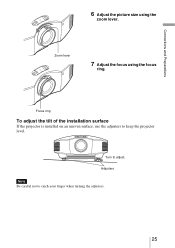
Connections and Preparations 6 Adjust the picture size using the focus ring. Adjusters Note Be careful not to adjust. Turn to catch your finger when turning the adjusters. 25 Zoom lever 7 Adjust the focus using the zoom lever. Focus ring To adjust the tilt of the installation surface If the projector is installed on an uneven surface, use the adjusters to keep the projector level.
Connections and Preparations 6 Adjust the picture size using the focus ring. Adjusters Note Be careful not to adjust. Turn to catch your finger when turning the adjusters. 25 Zoom lever 7 Adjust the focus using the zoom lever. Focus ring To adjust the tilt of the installation surface If the projector is installed on an uneven surface, use the adjusters to keep the projector level.

Operating Instructions
Page 28
... connected to the HDMI 2 connector Press INPUT to suit your taste. Projecting This section describes how to operate the projector to view the picture from the equipment connected to adjust the quality of the projector. (Only when the connected equipment supports Control for HDMI compatible.) 28 It also describes how to the...
... connected to the HDMI 2 connector Press INPUT to suit your taste. Projecting This section describes how to operate the projector to view the picture from the equipment connected to adjust the quality of the projector. (Only when the connected equipment supports Control for HDMI compatible.) 28 It also describes how to the...


