
Limited Warranty (U.S. Only)
Page 1
.... It is required. For specific instructions on how to obtain warranty service for your product, Visit Sony's Web Site: www.sony.com/service Or call the Sony Customer Information Service Center 1-800-222-SONY(7669) For an accessory or part not available from your exclusive remedies. 3-272-643-01 ® Car Audio LIMITED WARRANTY (U.S. Any parts or product replaced under this Limited Warranty, "refurbished...
.... It is required. For specific instructions on how to obtain warranty service for your product, Visit Sony's Web Site: www.sony.com/service Or call the Sony Customer Information Service Center 1-800-222-SONY(7669) For an accessory or part not available from your exclusive remedies. 3-272-643-01 ® Car Audio LIMITED WARRANTY (U.S. Any parts or product replaced under this Limited Warranty, "refurbished...
Marketing Specifications
Page 1
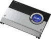
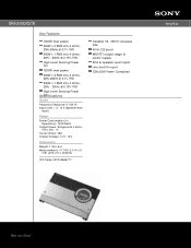
XM-2002GTR Key Features 1200W max power 200W x 2 RMS into 4 ohms, 20Hz-20kHz @ 0.1% THD 500W x 1 RMS into 4 ohms, 20Hz - 20kHz @ 0.15% THD High Level Sensing Power On 1200W max power 200W x 2 RMS into 4 ohms, 20Hz-20kHz @ 0.1% THD 500W x 1 RMS into 4 ohms, 20Hz - 20kHz @ 0.15% THD High Level Sensing Power SpeOcnifications Audio Frequency Response: 5 - 50k Hz Input Level: 1.2 - 12 V (Speaker level input) Power Power Consumption (in Operation): 1200 Watts Output Power: Bridged...
XM-2002GTR Key Features 1200W max power 200W x 2 RMS into 4 ohms, 20Hz-20kHz @ 0.1% THD 500W x 1 RMS into 4 ohms, 20Hz - 20kHz @ 0.15% THD High Level Sensing Power On 1200W max power 200W x 2 RMS into 4 ohms, 20Hz-20kHz @ 0.1% THD 500W x 1 RMS into 4 ohms, 20Hz - 20kHz @ 0.15% THD High Level Sensing Power SpeOcnifications Audio Frequency Response: 5 - 50k Hz Input Level: 1.2 - 12 V (Speaker level input) Power Power Consumption (in Operation): 1200 Watts Output Power: Bridged...
Marketing Specifications
Page 2
All other trademarks are subject to change without written permission is a trademark of their respective owners. Sony is prohibited. Features and specifications are property of Sony. Sony Electronics Inc. •16530 Via Esprillo •San Diego, CA 92127 •1-800-222-7669 •www.sony.com Last Updated: 10/16/2008 XM-2002GTR Amplifier Please visit the Dealer Network for more information at www.sony.com/dn ©2006 Sony Electronics Inc. Non-metric weights and measures are approximate. Reproduction in whole or in part without notice.
All other trademarks are subject to change without written permission is a trademark of their respective owners. Sony is prohibited. Features and specifications are property of Sony. Sony Electronics Inc. •16530 Via Esprillo •San Diego, CA 92127 •1-800-222-7669 •www.sony.com Last Updated: 10/16/2008 XM-2002GTR Amplifier Please visit the Dealer Network for more information at www.sony.com/dn ©2006 Sony Electronics Inc. Non-metric weights and measures are approximate. Reproduction in whole or in part without notice.
Service Guide
Page 1
... jack) Outputs Speaker outputs Speaker impedance 2 - 8 ohms Input level adjustment range 0.2 V- 2 V Maximum power output 35 watts per channel minimum RMS at rated output) Input remote current 5 mA Dimensions Approx. 130 x 25.4 x 80 mm (w/h/d) (51 / 8 x 1 x 31 / 4 inches) Mass Approx. 0.4 kg (14 oz.) Accessories supplied Mounting screw (1 set) Power and speaker connecting cord (1 set) RCA pin cord (1) (Except for the model for the United States and Canada) Design and specifications are subject to change without notice. SERVICE MANUAL ' RR! STEREO POWER AMPLIFIER SONY
... jack) Outputs Speaker outputs Speaker impedance 2 - 8 ohms Input level adjustment range 0.2 V- 2 V Maximum power output 35 watts per channel minimum RMS at rated output) Input remote current 5 mA Dimensions Approx. 130 x 25.4 x 80 mm (w/h/d) (51 / 8 x 1 x 31 / 4 inches) Mass Approx. 0.4 kg (14 oz.) Accessories supplied Mounting screw (1 set) Power and speaker connecting cord (1 set) RCA pin cord (1) (Except for the model for the United States and Canada) Design and specifications are subject to change without notice. SERVICE MANUAL ' RR! STEREO POWER AMPLIFIER SONY

Service Guide
Page 2
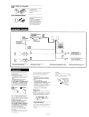
... amplifier. • Be sure to a metal point of the car. Be sure to only connect the passive speakers to direct sunlight or hot air from instruction manual. SECTION 1 GENERAL This section is equipped with that the speaker cords are not squeezed by any parts of the car to Install Prepare a sound mounting board with the supplied screws. How to avoid short circuits. Befestigen Sie den...
... amplifier. • Be sure to a metal point of the car. Be sure to only connect the passive speakers to direct sunlight or hot air from instruction manual. SECTION 1 GENERAL This section is equipped with that the speaker cords are not squeezed by any parts of the car to Install Prepare a sound mounting board with the supplied screws. How to avoid short circuits. Befestigen Sie den...
Service Guide
Page 3
... from direct sunlight or hot air from your car. Warning Use the specifioi fuse with this way • When installing the unit horivontally, be adjusted with correct amperage rating. It would be subject to protect the transistors and speakers if the amplifier malfunctions. However, even if the protection circuit is being supplied to the cassette player or tuner, check the connections. • This power amplifier employs a protection...
... from direct sunlight or hot air from your car. Warning Use the specifioi fuse with this way • When installing the unit horivontally, be adjusted with correct amperage rating. It would be subject to protect the transistors and speakers if the amplifier malfunctions. However, even if the protection circuit is being supplied to the cassette player or tuner, check the connections. • This power amplifier employs a protection...
Service Guide
Page 4
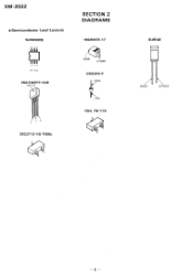
XM-2O22 • Semiconductor Lead Layouts NJM4580E HRH 1 2 34 !TOP VIEW) 2SA1048TP-YGR letter side )' SECTION 2 DIAGRAMS 1SS355TE-17 ANODE CATHODE DSA3A4-F cathode anode R D4 .7M-T1B 2SC2712-YG-TE85L GL8E48 ANODE CATHODE -4-
XM-2O22 • Semiconductor Lead Layouts NJM4580E HRH 1 2 34 !TOP VIEW) 2SA1048TP-YGR letter side )' SECTION 2 DIAGRAMS 1SS355TE-17 ANODE CATHODE DSA3A4-F cathode anode R D4 .7M-T1B 2SC2712-YG-TE85L GL8E48 ANODE CATHODE -4-

Service Guide
Page 5
... B - 5 Q302 C - 4 Note on Printed Wiring Board: • o- : parts extracted from POWER/SPEAKERS Connector (+B and REM) • Voltages are in n and V4 W or less unless otherwise specified. = : B+ Line • Power voltage is seen. PRINTED WIRING BOARD -MAIN Section- 2 •Semiconductor Location Ref. Voltage variations may be noted due to normal produc- C • : Pattern on Schematic Diagram: • All capacitors are taken...
... B - 5 Q302 C - 4 Note on Printed Wiring Board: • o- : parts extracted from POWER/SPEAKERS Connector (+B and REM) • Voltages are in n and V4 W or less unless otherwise specified. = : B+ Line • Power voltage is seen. PRINTED WIRING BOARD -MAIN Section- 2 •Semiconductor Location Ref. Voltage variations may be noted due to normal produc- C • : Pattern on Schematic Diagram: • All capacitors are taken...
Service Guide
Page 6
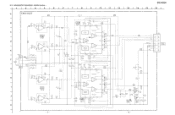
...R212008K 8.2 2.5O 13 041708+ 0111K2 1R1O2V120 R8101 LEVEL 062800 5 200 RV101-2 *),_ R682004 022200K6 * R2220076 * • R22200K9 T002.004570144670V7--+•11 .8 R22121 012407&9V + R2K12 2.5 14 O* VCC IC202 FILTER PROTECTOR c SCHEMATIC DIAGRAM -MAIN Section- 1 2 3 4 A Tr MAI N BOARD I 5 I 6 7 8 R309 220 9 10 11 B C E CN101 O F INPUT H J K C> C25)01,2V10+1 R2121K7 ... O• R1V18A13 2.6 14 * R22100K9 =C01.00647 FILTER BUFFER c„, 0.001 OGND STAND-BY SWITCH VCC IC102 PROTECTOR 12.5 PO P02 PROTECTOR Ofr ti .0212101 14 10V R115 6 - 2-2.
...R212008K 8.2 2.5O 13 041708+ 0111K2 1R1O2V120 R8101 LEVEL 062800 5 200 RV101-2 *),_ R682004 022200K6 * R2220076 * • R22200K9 T002.004570144670V7--+•11 .8 R22121 012407&9V + R2K12 2.5 14 O* VCC IC202 FILTER PROTECTOR c SCHEMATIC DIAGRAM -MAIN Section- 1 2 3 4 A Tr MAI N BOARD I 5 I 6 7 8 R309 220 9 10 11 B C E CN101 O F INPUT H J K C> C25)01,2V10+1 R2121K7 ... O• R1V18A13 2.6 14 * R22100K9 =C01.00647 FILTER BUFFER c„, 0.001 OGND STAND-BY SWITCH VCC IC102 PROTECTOR 12.5 PO P02 PROTECTOR Ofr ti .0212101 14 10V R115 6 - 2-2.
Service Guide
Page 7
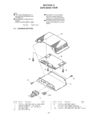
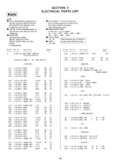
...parts with no reference number in the exploded views are seldom required for routine service. Description Remark 1 1-765-110-11 CORD (WITH CONNECTOR) (POWER/...FUSE (BRADE TYPE) (AUTO FUSE) (7.5A/32V) Part No. No. SECTION 3 EXPLODED VIEW NOTE: • -XX,-X mean standardized parts, so they are not supplied. 5 4 3 2 6 4 7 F301 Ref. Part No. Ref.No. CHASSIS SECTION • Items marked "* " are not stocked since they may have some differences from the original one. • Color Indication of Appearance Parts Example: KNOB, BALANCE (WHITE)...(RED) Parts color Cabinet's color...
...parts with no reference number in the exploded views are seldom required for routine service. Description Remark 1 1-765-110-11 CORD (WITH CONNECTOR) (POWER/...FUSE (BRADE TYPE) (AUTO FUSE) (7.5A/32V) Part No. No. SECTION 3 EXPLODED VIEW NOTE: • -XX,-X mean standardized parts, so they are not supplied. 5 4 3 2 6 4 7 F301 Ref. Part No. Ref.No. CHASSIS SECTION • Items marked "* " are not stocked since they may have some differences from the original one. • Color Indication of Appearance Parts Example: KNOB, BALANCE (WHITE)...(RED) Parts color Cabinet's color...
Service Guide
Page 8
... indicating parts by reference • COILS number, please...diagrams or the components used on the set. • -XX and -X mean standardized parts, so they may have some difference from the parts... 1-563-716-21 JACK, PIN 2P (INPUT) CN301 1-691-786-11 PIN, CONNECTOR (PC BOARD) 10P (POWER/SPEAKERS) < DIODE > C106 1-...POWER) D303 8-719-988-62 DIODE 1SS355 D304 8-719-157-23 DIODE RD4.7M-B < FUSE > F301 1-532-797-11 FUSE (BRADE TYPE) (AUTO FUSE...1/10W MAIN SECTION 3 ELECTRICAL PARTS LIST NOTE: • Due to standardization, replacements in the parts list may be anticipated when ordering ...
... indicating parts by reference • COILS number, please...diagrams or the components used on the set. • -XX and -X mean standardized parts, so they may have some difference from the parts... 1-563-716-21 JACK, PIN 2P (INPUT) CN301 1-691-786-11 PIN, CONNECTOR (PC BOARD) 10P (POWER/SPEAKERS) < DIODE > C106 1-...POWER) D303 8-719-988-62 DIODE 1SS355 D304 8-719-157-23 DIODE RD4.7M-B < FUSE > F301 1-532-797-11 FUSE (BRADE TYPE) (AUTO FUSE...1/10W MAIN SECTION 3 ELECTRICAL PARTS LIST NOTE: • Due to standardization, replacements in the parts list may be anticipated when ordering ...
Service Guide
Page 10
English 94A1883-1 Printed in Japan ©1994.1 Published by Audio Sector Quality Assurance Dept. XM-2022 9-959-264-11 Sony Corporation Mobil Electronics Group - 12 -
English 94A1883-1 Printed in Japan ©1994.1 Published by Audio Sector Quality Assurance Dept. XM-2022 9-959-264-11 Sony Corporation Mobil Electronics Group - 12 -


