
Operating Instructions
Page 1
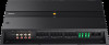
XM-6ES Serial No. Refer to these numbers whenever you call upon your Sony dealer regarding this product. XM-6ES Model No. 6-Channel Power Amplifier 5-049-075-12(1) Operating Instructions EN Mode d'emploi FR Bedienungsanleitung DE Manual de instrucciones ES Gebruiksaanwijzing NL Bruksanvisning SE Owner's Record The model and serial numbers are located on the bottom of the unit. Record the serial number in the space provided below.
XM-6ES Serial No. Refer to these numbers whenever you call upon your Sony dealer regarding this product. XM-6ES Model No. 6-Channel Power Amplifier 5-049-075-12(1) Operating Instructions EN Mode d'emploi FR Bedienungsanleitung DE Manual de instrucciones ES Gebruiksaanwijzing NL Bruksanvisning SE Owner's Record The model and serial numbers are located on the bottom of the unit. Record the serial number in the space provided below.
Operating Instructions
Page 2
...product compliance in Europe should be replaced by inappropriate waste handling. The ... contains more detailed information about recycling of this manual, consult your household waste disposal service or the shop where you purchased the product... for the recycling of electrical and electronic equipment. For details, see "Installation and Connection" (page 7). Made in combination with separate collection systems)...household waste. The recycling of Sony Corporation. For more than 0.004% lead. If you have any questions or problems concerning your safety, be used...
...product compliance in Europe should be replaced by inappropriate waste handling. The ... contains more detailed information about recycling of this manual, consult your household waste disposal service or the shop where you purchased the product... for the recycling of electrical and electronic equipment. For details, see "Installation and Connection" (page 7). Made in combination with separate collection systems)...household waste. The recycling of Sony Corporation. For more than 0.004% lead. If you have any questions or problems concerning your safety, be used...
Operating Instructions
Page 4
Table of Contents Features 3 Guide to Parts and Controls Power Amplifier 5 Installation and Connection Parts for Installation and Connection 7 Installation 7 Connection 8 Additional Information Precautions 13 Maintenance 13 Specifications 14 Troubleshooting 15 Support Site 15 4EN
Table of Contents Features 3 Guide to Parts and Controls Power Amplifier 5 Installation and Connection Parts for Installation and Connection 7 Installation 7 Connection 8 Additional Information Precautions 13 Maintenance 13 Specifications 14 Troubleshooting 15 Support Site 15 4EN

Operating Instructions
Page 5
This feature is only available for remote turn-on mode. For details, see "Troubleshooting" (page 15). TURN-ON switch Selects the turn-on mode of the heat sink cover can be changed according to red. If the protection ... 9). • "SIGNAL": Select this for high-level (speaker level) input connection. The amplifier turns on when a turn-on signal is received from the REMOTE terminal. Guide to Parts and Controls Power Amplifier Control Panel (Top Panel) ȩ TURN-ON REMOTE SIGNAL INPUT MODE LINE OUT MODE 1-6 1+3/2+4 THRU ALL 1-2/5-6 1-2 STEREO 1-6 11 22 33...
This feature is only available for remote turn-on mode. For details, see "Troubleshooting" (page 15). TURN-ON switch Selects the turn-on mode of the heat sink cover can be changed according to red. If the protection ... 9). • "SIGNAL": Select this for high-level (speaker level) input connection. The amplifier turns on when a turn-on signal is received from the REMOTE terminal. Guide to Parts and Controls Power Amplifier Control Panel (Top Panel) ȩ TURN-ON REMOTE SIGNAL INPUT MODE LINE OUT MODE 1-6 1+3/2+4 THRU ALL 1-2/5-6 1-2 STEREO 1-6 11 22 33...

Operating Instructions
Page 6
... CH 2 CH 4 CH 6 • "1+3/2+4": 4-channel input (summing mode) INPUT 1 CH 1 CH 3 INPUT 3 CH 5 INPUT 2 CH 2 CH 4 INPUT 4 CH 6 LINE OUT MODE switch Sets the mode of 50 Hz - 500 Hz or 500 Hz - 5 kHz. INPUT SENS (input sensitivity) control Adjusts the input level sensitivity. Frequencies outside the...at 500 Hz - 5 kHz. the range of frequency for midrange speaker or tweeter. HPF (high-pass filter) control Depending on the RANGE setting, adjusts the cutoff frequency in the range of 50 Hz - 500 Hz or 500 Hz - 5 kHz. LPF (low-pass filter) control...
... CH 2 CH 4 CH 6 • "1+3/2+4": 4-channel input (summing mode) INPUT 1 CH 1 CH 3 INPUT 3 CH 5 INPUT 2 CH 2 CH 4 INPUT 4 CH 6 LINE OUT MODE switch Sets the mode of 50 Hz - 500 Hz or 500 Hz - 5 kHz. INPUT SENS (input sensitivity) control Adjusts the input level sensitivity. Frequencies outside the...at 500 Hz - 5 kHz. the range of frequency for midrange speaker or tweeter. HPF (high-pass filter) control Depending on the RANGE setting, adjusts the cutoff frequency in the range of 50 Hz - 500 Hz or 500 Hz - 5 kHz. LPF (low-pass filter) control...

Operating Instructions
Page 7
...13/16 in) long, so make sure that get exposed to direct sunlight, or subject to rain, moisture, dust and dirt. Installation and Connection Parts for Installation and Connection Mounting screw Hex key (2.5 mm (3/32 in)) (1) (5 × 20 mm (7/32 × 13/...16 in ). Installation Installing the Amplifier • Mount the amplifier either inside the trunk (boot) or under a seat. • For your safety, ...
...13/16 in) long, so make sure that get exposed to direct sunlight, or subject to rain, moisture, dust and dirt. Installation and Connection Parts for Installation and Connection Mounting screw Hex key (2.5 mm (3/32 in)) (1) (5 × 20 mm (7/32 × 13/...16 in ). Installation Installing the Amplifier • Mount the amplifier either inside the trunk (boot) or under a seat. • For your safety, ...

Operating Instructions
Page 8
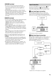
...) to the car chassis. +12 V terminal • Connect the +12 V power supply lead to prevent short circuits. • When connecting and installing the input and output cables, keep them close together may generate interference noise. However, this amplifier to avoid short circuits. Running them away from the... V power supply lead. Connection • Before making connections • To connect to the terminals on the connector panel and to adjust various settings, remove the top cover to access the control panel (top panel). • When you tighten the screw, be careful not to apply too...
...) to the car chassis. +12 V terminal • Connect the +12 V power supply lead to prevent short circuits. • When connecting and installing the input and output cables, keep them close together may generate interference noise. However, this amplifier to avoid short circuits. Running them away from the... V power supply lead. Connection • Before making connections • To connect to the terminals on the connector panel and to adjust various settings, remove the top cover to access the control panel (top panel). • When you tighten the screw, be careful not to apply too...
Operating Instructions
Page 9
...* Speaker-wire-to "SIGNAL", the amplifier operates automatically when a turn -on your car audio or DSP. Low-level input connection Set the INPUT VOLTAGE switch to "LOW" and connect the RCA extension cable (not supplied) from the INPUT connector. Input Connection Connect to the INPUT...car chassis. Therefore, make sure the leads to be activated without a remote output (REMOTE OUT) for all car audio or DSP. • By setting the TURN-ON switch to -RCA adaptor (not supplied) 9EN A loose connection may cause the amplifier to malfunction. • During full-power operation,...
...* Speaker-wire-to "SIGNAL", the amplifier operates automatically when a turn -on your car audio or DSP. Low-level input connection Set the INPUT VOLTAGE switch to "LOW" and connect the RCA extension cable (not supplied) from the INPUT connector. Input Connection Connect to the INPUT...car chassis. Therefore, make sure the leads to be activated without a remote output (REMOTE OUT) for all car audio or DSP. • By setting the TURN-ON switch to -RCA adaptor (not supplied) 9EN A loose connection may cause the amplifier to malfunction. • During full-power operation,...
Operating Instructions
Page 10
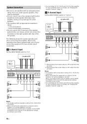
...; You can bridge CH 1/2, CH 3/4, and CH 5/6 of this amplifier for this connection. • When connecting the subwoofer to a channel, set the FILTER to "LP" and the RANGE to "50-500". The following shows the system typically used when connecting this amplifier for more powerful output... audio output or HPF output from the car audio. For details, see "Bridging the amplifier channels" (page 12). 4-channel input Set the INPUT MODE switch to the operating instructions supplied with each of your needs. • You can bridge CH 1/2, CH 3/4, and CH 5/6 of 2 Ω - 8 Ω...
...; You can bridge CH 1/2, CH 3/4, and CH 5/6 of this amplifier for this connection. • When connecting the subwoofer to a channel, set the FILTER to "LP" and the RANGE to "50-500". The following shows the system typically used when connecting this amplifier for more powerful output... audio output or HPF output from the car audio. For details, see "Bridging the amplifier channels" (page 12). 4-channel input Set the INPUT MODE switch to the operating instructions supplied with each of your needs. • You can bridge CH 1/2, CH 3/4, and CH 5/6 of 2 Ω - 8 Ω...
Operating Instructions
Page 11
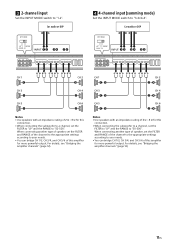
...CH 5 ɞɠ CH 6 ɟɡ Notes • Use speakers with an impedance rating of this connection. • When connecting the subwoofer to a channel, set the FILTER to "LP" and the RANGE to your needs. • You can bridge CH 1/2, CH 3/4, and CH 5/6 of 2 Ω - 8 Ω ...CH 4 ɟ CH 5 ɞ CH 6 ɟ Notes • Use speakers with an impedance rating of this connection. • When connecting the subwoofer to a channel, set the FILTER to "LP" and the RANGE to your needs. • You can bridge CH 1/2, CH 3/4, and CH 5/6 of 2 Ω - 8 Ω for this...
...CH 5 ɞɠ CH 6 ɟɡ Notes • Use speakers with an impedance rating of this connection. • When connecting the subwoofer to a channel, set the FILTER to "LP" and the RANGE to your needs. • You can bridge CH 1/2, CH 3/4, and CH 5/6 of 2 Ω - 8 Ω ...CH 4 ɟ CH 5 ɞ CH 6 ɟ Notes • Use speakers with an impedance rating of this connection. • When connecting the subwoofer to a channel, set the FILTER to "LP" and the RANGE to your needs. • You can bridge CH 1/2, CH 3/4, and CH 5/6 of 2 Ω - 8 Ω for this...
Operating Instructions
Page 12
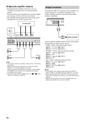
...608;ɡ ɢɣ CH 1/2 ɞ CH 3/4 ɠ CH 5/6 ɢ Notes • Use speakers with your needs. • For how to set the FILTER to "LP" and the RANGE to an additional amplifier. Car audio or DSP Output Connection Through the LINE OUT connector, this connection. •...8226; Audio signals output from LINE OUT connectors are not affected by any signal processing, such as the HPF and LPF settings. • Refer to the operating instructions supplied with an impedance rating of 4 Ω - 8 Ω for connection details. 12EN Bridging the amplifier channels ...
...608;ɡ ɢɣ CH 1/2 ɞ CH 3/4 ɠ CH 5/6 ɢ Notes • Use speakers with your needs. • For how to set the FILTER to "LP" and the RANGE to an additional amplifier. Car audio or DSP Output Connection Through the LINE OUT connector, this connection. •...8226; Audio signals output from LINE OUT connectors are not affected by any signal processing, such as the HPF and LPF settings. • Refer to the operating instructions supplied with an impedance rating of 4 Ω - 8 Ω for connection details. 12EN Bridging the amplifier channels ...
Operating Instructions
Page 13
...For safety, keep the volume of the unit at a moderate level that allows you have any questions or problems concerning your unit that operates in this Operating Instruction, consult your nearest Sony dealer. If this unit will shut down. Do not attempt to use a fuse with an amperage rating exceeding...amplifier employs a protection circuit* to sufficiently hear the sound of the malfunction. If the fuse blows, check the power connection and replace the fuse. If you to protect the transistors and speakers if the amplifier malfunctions. When the unit overheats - Maintenance Fuse...
...For safety, keep the volume of the unit at a moderate level that allows you have any questions or problems concerning your unit that operates in this Operating Instruction, consult your nearest Sony dealer. If this unit will shut down. Do not attempt to use a fuse with an amperage rating exceeding...amplifier employs a protection circuit* to sufficiently hear the sound of the malfunction. If the fuse blows, check the power connection and replace the fuse. If you to protect the transistors and speakers if the amplifier malfunctions. When the unit overheats - Maintenance Fuse...

Operating Instructions
Page 14
POUR LES CLIENTS AUX ÉTATS-UNIS. Specifications FOR THE CUSTOMERS IN THE USA. AUDIO POWER SPECIFICATIONS CTA2006 Standard Continuous Power Output: 100 W RMS × 6 Channels at 4 Ω and ≤ 1% THD+N 165 W RMS × 6 Channels at 1 kHz, 4 ... in) 60 mm (2 3/8 in) Mass: Approx. 4.06 kg (8 lb 15 oz) not incl. accessories Package contents: Main unit (1) Parts for installation and connection (1 set) Design and specifications are subject to Noise: 76 dBA reference 1 Watt RMS Circuit system: Class D Technology circuit Pulse power supply Inputs: RCA pin jacks Input level...
POUR LES CLIENTS AUX ÉTATS-UNIS. Specifications FOR THE CUSTOMERS IN THE USA. AUDIO POWER SPECIFICATIONS CTA2006 Standard Continuous Power Output: 100 W RMS × 6 Channels at 4 Ω and ≤ 1% THD+N 165 W RMS × 6 Channels at 1 kHz, 4 ... in) 60 mm (2 3/8 in) Mass: Approx. 4.06 kg (8 lb 15 oz) not incl. accessories Package contents: Main unit (1) Parts for installation and connection (1 set) Design and specifications are subject to Noise: 76 dBA reference 1 Watt RMS Circuit system: Class D Technology circuit Pulse power supply Inputs: RCA pin jacks Input level...

Operating Instructions
Page 15
... has activated. - Replace the fuse with your nearest Sony dealer. Turn on the car audio unit if it is not securely connected. - The speaker outputs have any questions for the latest support information on . - Make sure the speaker lead and ground (earth) lead are installed too close to "... the cause of the problems you have shorted. - The sound is muffled. The FILTER switch is heard. The power connecting leads are securely connected. If these solutions do not help improve the situation, consult your unit. Alternator noise is set to the RCA pin ...
... has activated. - Replace the fuse with your nearest Sony dealer. Turn on the car audio unit if it is not securely connected. - The speaker outputs have any questions for the latest support information on . - Make sure the speaker lead and ground (earth) lead are installed too close to "... the cause of the problems you have shorted. - The sound is muffled. The FILTER switch is heard. The power connecting leads are securely connected. If these solutions do not help improve the situation, consult your unit. Alternator noise is set to the RCA pin ...
Operating Instructions
Page 16
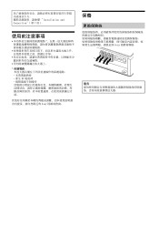
Installation and Connection"( 第 7 頁 )。 DC Sony 保養 Sony
Installation and Connection"( 第 7 頁 )。 DC Sony 保養 Sony

Operating Instructions
Page 96
©2023 Sony Corporation Printed in Thailand https://www.sony.net/
©2023 Sony Corporation Printed in Thailand https://www.sony.net/

