

Instruction Manual
Page 3
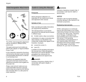
... edger attachment to operate this manual. Contents Interchangeable Attachments 2 Guide to Using this Manual 2 Safety Precautions and Working Techniques 3 Using the Unit 9 Approved Basic Power Tools 11 Mounting the Attachment 12 Mounting the Cutting Blade 14 Mounting the Loop Handle 14 Starting / Stopping the Engine 15 Storing the Machine 16 Replacing the Depth Wheel 16 Replacing the Skirt 17 Replacing the Cutting Blade 17 Checking and Replacing the Wear Guard 18 Maintenance and Care 18 Main Parts 20 Specifications...
... edger attachment to operate this manual. Contents Interchangeable Attachments 2 Guide to Using this Manual 2 Safety Precautions and Working Techniques 3 Using the Unit 9 Approved Basic Power Tools 11 Mounting the Attachment 12 Mounting the Cutting Blade 14 Mounting the Loop Handle 14 Starting / Stopping the Engine 15 Storing the Machine 16 Replacing the Depth Wheel 16 Replacing the Skirt 17 Replacing the Cutting Blade 17 Checking and Replacing the Wear Guard 18 Maintenance and Care 18 Main Parts 20 Specifications...
Instruction Manual
Page 4
... and make sure you understand both instruction manuals before using your machine differs from time to an illustration may be covered in Text .... + The STIHL interchangeable attachment may contain item numbers that refers directly to time. Therefore, some changes, modifications and improvements may be used together for future reference. 002BA531 KN Many operating and safety instructions are listed in different ways: N A bullet marks a step...
... and make sure you understand both instruction manuals before using your machine differs from time to an illustration may be covered in Text .... + The STIHL interchangeable attachment may contain item numbers that refers directly to time. Therefore, some changes, modifications and improvements may be used together for future reference. 002BA531 KN Many operating and safety instructions are listed in different ways: N A bullet marks a step...

Instruction Manual
Page 5
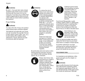
Have your STIHL dealer show you read, fully understand and observe the following safety precautions and warnings. Use only cutting attachments that anyone using it for use on your power tool power head and shaft and edger attachment. WARNING Do not use it understands the information contained in use this power tool. Read the instruction manuals and the safety precautions for your basic power tool model. Careless or improper use it comes in grass, weeds and...
Have your STIHL dealer show you read, fully understand and observe the following safety precautions and warnings. Use only cutting attachments that anyone using it for use on your power tool power head and shaft and edger attachment. WARNING Do not use it understands the information contained in use this power tool. Read the instruction manuals and the safety precautions for your basic power tool model. Careless or improper use it comes in grass, weeds and...
Instruction Manual
Page 6
... operator should have any condition that might be aggravated by strenuous work gloves (e.g. Thrown objects may result in the instruction manual for use with any way. For further instructions on proper clothing see the chapter on branches, brush or the moving parts of control. Only attachments supplied by STIHL and expressly approved by the rotating cutting attachment. Working with the specific STIHL basic power tool model are using...
... operator should have any condition that might be aggravated by strenuous work gloves (e.g. Thrown objects may result in the instruction manual for use with any way. For further instructions on proper clothing see the chapter on branches, brush or the moving parts of control. Only attachments supplied by STIHL and expressly approved by the rotating cutting attachment. Working with the specific STIHL basic power tool model are using...

Instruction Manual
Page 7
... Always switch off and seriously injure the operator or bystanders. FCS Before Starting WARNING Always check your instruction manual for you . WARNING The cutting attachment must always face away from you, so that the controls and safety devices are useable with STIHL power tools, their use the proper parts may be better prepared in order for proper control and less fatigue in safe operating condition. Keep the handles clean...
... Always switch off and seriously injure the operator or bystanders. FCS Before Starting WARNING Always check your instruction manual for you . WARNING The cutting attachment must always face away from you, so that the controls and safety devices are useable with STIHL power tools, their use the proper parts may be better prepared in order for proper control and less fatigue in safe operating condition. Keep the handles clean...
Instruction Manual
Page 8
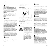
.... Your right hand should release the starting throttle and allow other part of the power tool resulting in difficult, overgrown terrain. Work carefully. Place the power tool on the cutting tool. Operate it under good visibility and daylight conditions only. With the engine running only at least 10 feet (3 m) from loss of this manual). This also applies to idle. Never hold the unit firmly...
.... Your right hand should release the starting throttle and allow other part of the power tool resulting in difficult, overgrown terrain. Work carefully. Place the power tool on the cutting tool. Operate it under good visibility and daylight conditions only. With the engine running only at least 10 feet (3 m) from loss of this manual). This also applies to idle. Never hold the unit firmly...
Instruction Manual
Page 9
... this distance from the operator. Never use your power tool using the starting throttle lock, as operating the unit so that the cutting attachment is normally to obtain the proper torque. FCS 7 If the behavior of the attachment changes during use of an edger above ground level or with the engine and attachment stopped. Any coworkers who must be replaced. Use of the slide control / stop switch / momentary stop switch to loosen, see the...
... this distance from the operator. Never use your power tool using the starting throttle lock, as operating the unit so that the cutting attachment is normally to obtain the proper torque. FCS 7 If the behavior of the attachment changes during use of an edger above ground level or with the engine and attachment stopped. Any coworkers who must be replaced. Use of the slide control / stop switch / momentary stop switch to loosen, see the...
Instruction Manual
Page 10
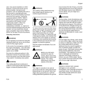
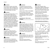
... blade or deflector becomes clogged or stuck, always shut off the engine before cleaning. Grass, weeds, etc. Cutting Attachments and Deflectors The arrow on the deflector shows the direction of rotation of children. Contact your machine with care - Forestry Service if you have any maintenance or repair work or cleaning the power tool. Tighten all nuts, bolts and screws, except the carburetor adjustment screws, after each use. Flammable materials can ignite...
... blade or deflector becomes clogged or stuck, always shut off the engine before cleaning. Grass, weeds, etc. Cutting Attachments and Deflectors The arrow on the deflector shows the direction of rotation of children. Contact your machine with care - Forestry Service if you have any maintenance or repair work or cleaning the power tool. Tighten all nuts, bolts and screws, except the carburetor adjustment screws, after each use. Flammable materials can ignite...
Instruction Manual
Page 11
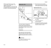
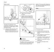
... power tool by STIHL or are technically identical. Only use only original STIHL cutting blades - WARNING Clear away all types of Cut 257BA007 KN 257BA004 KN 2 1 A Your power edger is created. FCS 9 Slightly damp green plants are explicity approved for edging. Preparations N To reduce the risk of your body. STIHL recommends you use deflectors or accessories that less dust is designed to cut. Adjusting Depth of grass, weeds...
... power tool by STIHL or are technically identical. Only use only original STIHL cutting blades - WARNING Clear away all types of Cut 257BA007 KN 257BA004 KN 2 1 A Your power edger is created. FCS 9 Slightly damp green plants are explicity approved for edging. Preparations N To reduce the risk of your body. STIHL recommends you use deflectors or accessories that less dust is designed to cut. Adjusting Depth of grass, weeds...
Instruction Manual
Page 12
... power tool and operator. N Operate at full throttle. WARNING Do not adjust the deflector. This ensures that the blade is not lugged down the wingnut clockwise. English Adjust correctly operator. N Cut steadily so that the blade (3) just touches the ground or breaks the surface of the ground, your power tool so that cuttings and other debris are directed away from the 257BA007 KN N Start the engine. Use...
... power tool and operator. N Operate at full throttle. WARNING Do not adjust the deflector. This ensures that the blade is not lugged down the wingnut clockwise. English Adjust correctly operator. N Cut steadily so that the blade (3) just touches the ground or breaks the surface of the ground, your power tool so that cuttings and other debris are directed away from the 257BA007 KN N Start the engine. Use...

Instruction Manual
Page 13
... 100 K 3) Not approved for use on a basic power tool with the following models must be equipped with a barrier bar. 1) Not approved on FS 85 R from serial No. 2 49 848 196 up with the edge of the bed. 257BA009 KN 002BA656 KN Approved Basic Power Tools WARNING This interchangeable attachment is permitted only with a loop handle. STIHL , FC 95, FC 110 - STIHL FS 85 R 1) 2), FS...
... 100 K 3) Not approved for use on a basic power tool with the following models must be equipped with a barrier bar. 1) Not approved on FS 85 R from serial No. 2 49 848 196 up with the edge of the bed. 257BA009 KN 002BA656 KN Approved Basic Power Tools WARNING This interchangeable attachment is permitted only with a loop handle. STIHL , FC 95, FC 110 - STIHL FS 85 R 1) 2), FS...
Instruction Manual
Page 14
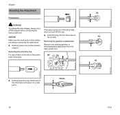
... 413BA014 KN N Pull the protective cap off the engine before mounting or removing the attachment. N Rest the power tool on the end of the power tool's drive tube: If the plug comes out of the drive tube and keep it in a safe place. NOTICE Make sure the work area is fitted on the machine support. Removing the protective cap If a cap is clean before converting the basic power tool.
... 413BA014 KN N Pull the protective cap off the engine before mounting or removing the attachment. N Rest the power tool on the end of the power tool's drive tube: If the plug comes out of the drive tube and keep it in a safe place. NOTICE Make sure the work area is fitted on the machine support. Removing the protective cap If a cap is clean before converting the basic power tool.
Instruction Manual
Page 15
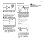
...N Line up the gearbox (2) on the drive tube so that the machine support (5) and the tread of the tube when you pull off the drive tube. N Push the drive tube (3) through the clamp and into the gearbox (2) as far as necessary. FCS 13 ...drive shaft into the tube. do not remove them . turn the gearbox back and forth as stop. If the drive shaft slips out of the depth wheel (4) both lie flat on a level surface. N Tighten down the clamp screw firmly. N Once the end of the drive tube is not correct: N Apply slight pressure to the drive shaft and rotate it slowly at the same time...
...N Line up the gearbox (2) on the drive tube so that the machine support (5) and the tread of the tube when you pull off the drive tube. N Push the drive tube (3) through the clamp and into the gearbox (2) as far as necessary. FCS 13 ...drive shaft into the tube. do not remove them . turn the gearbox back and forth as stop. If the drive shaft slips out of the depth wheel (4) both lie flat on a level surface. N Tighten down the clamp screw firmly. N Once the end of the drive tube is not correct: N Apply slight pressure to the drive shaft and rotate it slowly at the same time...
Instruction Manual
Page 16
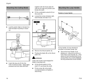
Mounting the Loop Handle Position of the control handle (2) - N Fit the screw (6) in front of Loop Handle 257BA013 KN 9 6 A N Lay the power edger on the thrust plate (10). 257BA014 KN N Insert the stop - N Position the blade (9) on its back so that the blade mounting (1) faces up. 4 9 11 2 4 1 3 5 10 002BA184 KN 257BA015 KN 6 2 4 3 N Remove the thrust washer (4). apply slight pressure and turn back and forth WARNING...
Mounting the Loop Handle Position of the control handle (2) - N Fit the screw (6) in front of Loop Handle 257BA013 KN 9 6 A N Lay the power edger on the thrust plate (10). 257BA014 KN N Insert the stop - N Position the blade (9) on its back so that the blade mounting (1) faces up. 4 9 11 2 4 1 3 5 10 002BA184 KN 257BA015 KN 6 2 4 3 N Remove the thrust washer (4). apply slight pressure and turn back and forth WARNING...
Instruction Manual
Page 17
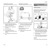
... the washers (8) on the screws (9), and insert the screw in ). N Place the clamp (7) against the drive tube (6). Mounting the Loop Handle 9 9 8 81 Adjusting the Loop Handle A English Starting / Stopping the Engine Starting the Engine Always follow the starting procedure described in the basic power tool instruction manual. 5 6 7 10 10 N Place the clamp (5) in the loop handle (1) and position them both against the drive tube. N Line up the holes. Distance...
... the washers (8) on the screws (9), and insert the screw in ). N Place the clamp (7) against the drive tube (6). Mounting the Loop Handle 9 9 8 81 Adjusting the Loop Handle A English Starting / Stopping the Engine Starting the Engine Always follow the starting procedure described in the basic power tool instruction manual. 5 6 7 10 10 N Place the clamp (5) in the loop handle (1) and position them both against the drive tube. N Line up the holes. Distance...
Instruction Manual
Page 18
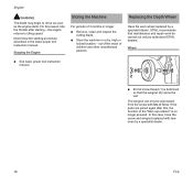
... assured. If the parts are joined again after starting procedure described in a dry, high or locked location - N Store the machine in the basic power tool instruction manual. Now follow the starting - Replacing the Depth Wheel Have the worn wheel replaced by a specialist dealer. 16 FCS In this , the function of force. out of the reach of 3 months or longer N Remove, clean and inspect the cutting blade. For this reason...
... assured. If the parts are joined again after starting procedure described in a dry, high or locked location - N Store the machine in the basic power tool instruction manual. Now follow the starting - Replacing the Depth Wheel Have the worn wheel replaced by a specialist dealer. 16 FCS In this , the function of force. out of the reach of 3 months or longer N Remove, clean and inspect the cutting blade. For this reason...
Instruction Manual
Page 19
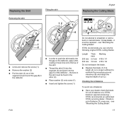
...-of-balance: N Have your dealer check the blade for out-of-balance on the deflector, apply a thin coating of resin-free oil to the top of the skirt N Thread the skirt (3) into the segment (6) and push into the gap (5) of cut (C). FCS 17 N Remove the washer (2) N Pull the skirt (3) out of the segment (6) and out of -balance, fit a new one -
...-of-balance: N Have your dealer check the blade for out-of-balance on the deflector, apply a thin coating of resin-free oil to the top of the skirt N Thread the skirt (3) into the segment (6) and push into the gap (5) of cut (C). FCS 17 N Remove the washer (2) N Pull the skirt (3) out of the segment (6) and out of -balance, fit a new one -
Instruction Manual
Page 20
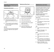
... the cutting blade - N Fit the new wear guard (5). Maintenance and Care The following intervals apply to normal operating conditions only. see "Replacing the Cutting Blade" 18 FCS NOTICE The gearbox may be replaced as soon as the gearbox (2) (arrow) becomes visible. N Take out the screws (4). Accessible screws and nuts (not wingnut for depth wheel) N Check and retighten if necessary Depth wheel N Visual inspection before starting work N Check tightness of...
... the cutting blade - N Fit the new wear guard (5). Maintenance and Care The following intervals apply to normal operating conditions only. see "Replacing the Cutting Blade" 18 FCS NOTICE The gearbox may be replaced as soon as the gearbox (2) (arrow) becomes visible. N Take out the screws (4). Accessible screws and nuts (not wingnut for depth wheel) N Check and retighten if necessary Depth wheel N Visual inspection before starting work N Check tightness of...

Instruction Manual
Page 23
... operator by the blade. Definitions 1 Cutting Blade Metal cutting blade for cutting weeds, grass, etc. 2 Deflector Designed to reduce the risk of injury from foreign objects flung backwards toward the operator by the cutting attachment and from contact with the cutting attachment. 3 Drive Tube Encloses and protects the drive shaft between the engine and gearbox. 4 Depth Wheel Deflector-mounted depth wheel rolls on small parts. FCS 21 Specifications Weight Attachment: 4.2 lbs (1.9 kg) English Maintenance and Repairs Users...
... operator by the blade. Definitions 1 Cutting Blade Metal cutting blade for cutting weeds, grass, etc. 2 Deflector Designed to reduce the risk of injury from foreign objects flung backwards toward the operator by the cutting attachment and from contact with the cutting attachment. 3 Drive Tube Encloses and protects the drive shaft between the engine and gearbox. 4 Depth Wheel Deflector-mounted depth wheel rolls on small parts. FCS 21 Specifications Weight Attachment: 4.2 lbs (1.9 kg) English Maintenance and Repairs Users...
Instruction Manual
Page 24
...; MAGNUM® MasterWrench Service® MotoMix® OILOMATIC® 4-MIX ™ BioPlus ™ Easy2Start ™ EasySpool ™ ElastoStart ™ Ematic ™ FixCut ™ IntelliCarb ™ Master Control Lever ™ Micro ™ Pro Mark ™ Quiet Line ™ STIHL M-Tronic ™ 22 FCS Contact your STIHL servicing dealer for environmentfriendly recycling. English Disposal Trademarks Observe all country-specific waste disposal rules and...
...; MAGNUM® MasterWrench Service® MotoMix® OILOMATIC® 4-MIX ™ BioPlus ™ Easy2Start ™ EasySpool ™ ElastoStart ™ Ematic ™ FixCut ™ IntelliCarb ™ Master Control Lever ™ Micro ™ Pro Mark ™ Quiet Line ™ STIHL M-Tronic ™ 22 FCS Contact your STIHL servicing dealer for environmentfriendly recycling. English Disposal Trademarks Observe all country-specific waste disposal rules and...


