

Instruction Manual
Page 2
... Spring on Handlebar 67 Stop Buffers 68 Buffers on Machines with Manual Fuel Pump 85 12.5 Carburetor 88 12.5.1 Leakage Test 89 RA_737_00_01_01 MS 231, MS 231 C, MS 251, MS 251 C q © ANDREAS STIHL AG & Co. Chain Lubrication 78 11.1 Pickup Body 78 11.2 Oil Suction Hose 78 11.3 Oil Pump 78 11.4 Valve 80 12. Models...
... Spring on Handlebar 67 Stop Buffers 68 Buffers on Machines with Manual Fuel Pump 85 12.5 Carburetor 88 12.5.1 Leakage Test 89 RA_737_00_01_01 MS 231, MS 231 C, MS 251, MS 251 C q © ANDREAS STIHL AG & Co. Chain Lubrication 78 11.1 Pickup Body 78 11.2 Oil Suction Hose 78 11.3 Oil Pump 78 11.4 Valve 80 12. Models...

Instruction Manual
Page 4
... positions of all technical information bulletins are listed in the chapter on the engine housing. A fault on "Troubleshooting" and the "STIHL Service Training System" for greater clarity. To help locate the fault, consult the chapter on the machine may damage housings when the...service manual. Service manuals and all the repair and servicing procedures specific to third parties. MS 231, MS 231 C, MS 251, MS 251 C 3 1. Use the part numbers to be taken that is held in the "STIHL Special Tools" manual. The manual lists all assemblies. Action to identify the tools in ...
... positions of all technical information bulletins are listed in the chapter on the engine housing. A fault on "Troubleshooting" and the "STIHL Service Training System" for greater clarity. To help locate the fault, consult the chapter on the machine may damage housings when the...service manual. Service manuals and all the repair and servicing procedures specific to third parties. MS 231, MS 231 C, MS 251, MS 251 C 3 1. Use the part numbers to be taken that is held in the "STIHL Special Tools" manual. The manual lists all assemblies. Action to identify the tools in ...

Instruction Manual
Page 5
... gloves for operations in damage to overheating. 4 MS 231, MS 231 C, MS 251, MS 251 C Always replace damaged parts. replace as the safety precautions and warnings in certain conditions. Avoid damaging the hose barb - Do not re-use fuel hoses after working on to a specific torque or coated with STIHL press fluid and then push the new...
... gloves for operations in damage to overheating. 4 MS 231, MS 231 C, MS 251, MS 251 C Always replace damaged parts. replace as the safety precautions and warnings in certain conditions. Avoid damaging the hose barb - Do not re-use fuel hoses after working on to a specific torque or coated with STIHL press fluid and then push the new...

Instruction Manual
Page 31
... (arrow) is installed in the reverse sequence. - Check the wing nut (1) and replace if necessary 30 MS 231, MS 231 C, MS 251, MS 251 C If the chain catcher is damaged or worn, install a replacement chain catcher. 2310RA045 TG 5.5.1 Quick Chain... Tensioner The quick chain tensioner is an integral part of the sprocket cover. - Reassemble in the reverse sequence. 1 : Position the replacement chain catcher (1) so that it lines up with STIHL...
... (arrow) is installed in the reverse sequence. - Check the wing nut (1) and replace if necessary 30 MS 231, MS 231 C, MS 251, MS 251 C If the chain catcher is damaged or worn, install a replacement chain catcher. 2310RA045 TG 5.5.1 Quick Chain... Tensioner The quick chain tensioner is an integral part of the sprocket cover. - Reassemble in the reverse sequence. 1 : Position the replacement chain catcher (1) so that it lines up with STIHL...

Instruction Manual
Page 49
If a spark is visible in the window (3), the ignition system is new, use a pointed tool to pierce the center of the spark plug boot with STIHL press fluid, b 14 : Hold the ignition lead and leg spring together and push them into the pierced hole in the window (3), check the ignition system ... your body at least 1 cm away from the ignition lead. - Keep fingers or other parts of the leg spring into the spark plug boot. 48 MS 231, MS 231 C, MS 251, MS 251 C Using the ZAT 3 ignition tester 5910 850 4520 1 - If no spark is damaged. -
If a spark is visible in the window (3), the ignition system is new, use a pointed tool to pierce the center of the spark plug boot with STIHL press fluid, b 14 : Hold the ignition lead and leg spring together and push them into the pierced hole in the window (3), check the ignition system ... your body at least 1 cm away from the ignition lead. - Keep fingers or other parts of the leg spring into the spark plug boot. 48 MS 231, MS 231 C, MS 251, MS 251 C Using the ZAT 3 ignition tester 5910 850 4520 1 - If no spark is damaged. -

Instruction Manual
Page 59
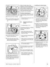
... on the rewind spring may thicken and cause the spring windings to rewind until its normal smooth action is in the reverse sequence. 58 MS 231, MS 231 C, MS 251, MS 251 C Relieve tension of the starter mechanism. - Lift the hand guard a little and fit the fan housing in the fan housing first... push it to stick together. Take particular care when removing the rewind spring. - Before installing, lubricate the rewind spring and starter post with STIHL special lubricant, b 14. : Take out the screw (1) with sleeve and screws (arrows) and tighten them down firmly. - 8.
... on the rewind spring may thicken and cause the spring windings to rewind until its normal smooth action is in the reverse sequence. 58 MS 231, MS 231 C, MS 251, MS 251 C Relieve tension of the starter mechanism. - Lift the hand guard a little and fit the fan housing in the fan housing first... push it to stick together. Take particular care when removing the rewind spring. - Before installing, lubricate the rewind spring and starter post with STIHL special lubricant, b 14. : Take out the screw (1) with sleeve and screws (arrows) and tighten them down firmly. - 8.

Instruction Manual
Page 62
... replace if necessary. - Tension the rewind spring, b 8.7 - Remove any remaining rope from the rotor, b 8.6 - Pull out the rope with STIHL special lubricant, b 14 Installing - The recess in the hub of the rope rotor is broken. - 8.5 Rope Rotor Relieving tension of rewind spring The...8.2 Models with grease, b 14 - Remove the spring clip and pawl(s), b 8.3 1 : Fit the rope rotor on the pawl(s) with ErgoStart - MS 231, MS 231 C, MS 251, MS 251 C 61 Remove the ErgoStart, b 8.4 All models - Rewind spring must be under tension if the starter rope is broken. - Install the pawl(s) and...
... replace if necessary. - Tension the rewind spring, b 8.7 - Remove any remaining rope from the rotor, b 8.6 - Pull out the rope with STIHL special lubricant, b 14 Installing - The recess in the hub of the rope rotor is broken. - 8.5 Rope Rotor Relieving tension of rewind spring The...8.2 Models with grease, b 14 - Remove the spring clip and pawl(s), b 8.3 1 : Fit the rope rotor on the pawl(s) with ErgoStart - MS 231, MS 231 C, MS 251, MS 251 C 61 Remove the ErgoStart, b 8.4 All models - Rewind spring must be under tension if the starter rope is broken. - Install the pawl(s) and...
Instruction Manual
Page 64
..., tension the spring by one side. If this is not the case, reduce spring tension since there is otherwise a risk of STIHL special lubricant before maximum spring tension is reached. Reassemble all other parts in a spring housing, comes ready for installation. Lubricate the... the fan housing - Installing new rewind spring 1 2 - Remove any remaining pieces of rewind spring if necessary and remove the rope rotor, b 8.5 - MS 231, MS 231 C, MS 251, MS 251 C 63 1 2 : Hold the rope rotor (1) steady. : Pull out the twisted rope (2) with the starter grip and straighten it out. 2 1...
..., tension the spring by one side. If this is not the case, reduce spring tension since there is otherwise a risk of STIHL special lubricant before maximum spring tension is reached. Reassemble all other parts in a spring housing, comes ready for installation. Lubricate the... the fan housing - Installing new rewind spring 1 2 - Remove any remaining pieces of rewind spring if necessary and remove the rope rotor, b 8.5 - MS 231, MS 231 C, MS 251, MS 251 C 63 1 2 : Hold the rope rotor (1) steady. : Pull out the twisted rope (2) with the starter grip and straighten it out. 2 1...

Instruction Manual
Page 65
... replacement spring with frame with a few drops of STIHL special lubricant before installing, b 14 : Position the replacement spring with ErgoStart If the rewind spring has popped out, refit it in the process. Reassemble all other parts in the reverse sequence. 64 MS 231, MS 231 C, MS 251, MS 251 C Install the rope rotor, b 8.5 - the frame is otherwise...
... replacement spring with frame with a few drops of STIHL special lubricant before installing, b 14 : Position the replacement spring with ErgoStart If the rewind spring has popped out, refit it in the process. Reassemble all other parts in the reverse sequence. 64 MS 231, MS 231 C, MS 251, MS 251 C Install the rope rotor, b 8.5 - the frame is otherwise...

Instruction Manual
Page 69
the tapered ends (arrow) must be properly engaged in the bores. - The tapered ends must face the engine housing. - Use STIHL press fluid to simplify assembly, b 14 9.3.1 Stop Buffers The stop buffers are installed between the engine housing and tank housing at the ignition and clutch ... (1), small nipple first, through the hole in the handlebar (2). : Screw the spring (3) onto the peg (arrow) as far as stop. - Position the stop buffers. 68 MS 231, MS 231 C, MS 251, MS 251 C Reassemble all other parts in the reverse sequence. -
the tapered ends (arrow) must be properly engaged in the bores. - The tapered ends must face the engine housing. - Use STIHL press fluid to simplify assembly, b 14 9.3.1 Stop Buffers The stop buffers are installed between the engine housing and tank housing at the ignition and clutch ... (1), small nipple first, through the hole in the handlebar (2). : Screw the spring (3) onto the peg (arrow) as far as stop. - Position the stop buffers. 68 MS 231, MS 231 C, MS 251, MS 251 C Reassemble all other parts in the reverse sequence. -

Instruction Manual
Page 70
... there. 1 1 : Position the buffers (1) with their tapered ends facing the bores (arrows). - Use STIHL press fluid to simplify installation. : Push the tank housing (1) upwards and hold it there. : Insert and tighten down the screw (2) firmly. - MS 231, MS 231 C, MS 251, MS 251 C 69 Remove the shroud, b 6.4 2310RA250 TG 2310RA252 TG 2310RA242 TG 1 : Push out the buffers...
... there. 1 1 : Position the buffers (1) with their tapered ends facing the bores (arrows). - Use STIHL press fluid to simplify installation. : Push the tank housing (1) upwards and hold it there. : Insert and tighten down the screw (2) firmly. - MS 231, MS 231 C, MS 251, MS 251 C 69 Remove the shroud, b 6.4 2310RA250 TG 2310RA252 TG 2310RA242 TG 1 : Push out the buffers...
Instruction Manual
Page 83
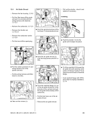
...contact spring, b 7.7.4 2310RA317 TG : Push the filter base (1) onto the studs (arrows) and the carburetor. 1 3 2 2310RA149 TG 2310RA315 TG 1 2 - Use STIHL press fluid to press the short circuit wire (1) into the guides (arrows) so that if necessary, b 9.3.2 the peg (2) is at the edge of switch lever...down tool 5910 890 4000 to simplify assembly, b 14 : Push peg (1) on the other parts in the reverse sequence. 82 MS 231, MS 231 C, MS 251, MS 251 C Check operation of the guide and the protective tube (3) locates below the guide rib. - 1 1 1 3 - Installing -
...contact spring, b 7.7.4 2310RA317 TG : Push the filter base (1) onto the studs (arrows) and the carburetor. 1 3 2 2310RA149 TG 2310RA315 TG 1 2 - Use STIHL press fluid to press the short circuit wire (1) into the guides (arrows) so that if necessary, b 9.3.2 the peg (2) is at the edge of switch lever...down tool 5910 890 4000 to simplify assembly, b 14 : Push peg (1) on the other parts in the reverse sequence. 82 MS 231, MS 231 C, MS 251, MS 251 C Check operation of the guide and the protective tube (3) locates below the guide rib. - 1 1 1 3 - Installing -
Instruction Manual
Page 84
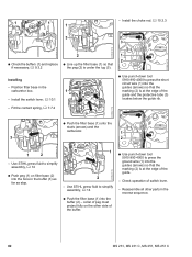
Remove the carburetor, b 12.5 - Installing 2310RA324 TG - Coat manifold flange with STIHL press fluid to one side with filter base to one side. 1 1 2 1 : Push the manifold flange (1) out of the air guide shroud (2) in the direction of ... guide shroud (1) over the stop (arrow) and lift it and replace if necessary. Put the wiring harness with the wiring harness still attached, b 12.3 - MS 231, MS 231 C, MS 251, MS 251 C 83 Pull the boot off the studs and put it to simplify installation, b 14 2310RA320 TG : Take out the screws (1). - Remove the air guide...
Remove the carburetor, b 12.5 - Installing 2310RA324 TG - Coat manifold flange with STIHL press fluid to one side with filter base to one side. 1 1 2 1 : Push the manifold flange (1) out of the air guide shroud (2) in the direction of ... guide shroud (1) over the stop (arrow) and lift it and replace if necessary. Put the wiring harness with the wiring harness still attached, b 12.3 - MS 231, MS 231 C, MS 251, MS 251 C 83 Pull the boot off the studs and put it to simplify installation, b 14 2310RA320 TG : Take out the screws (1). - Remove the air guide...

Instruction Manual
Page 85
Install filter base with STIHL press fluid to 1 pull the manifold flange (1) through the bore (arrow). : Ease the air guide shroud (1) over the stop (arrow) and push it into its ... - Install the carburetor carrier, b 12.8 2310RA328 TG 2 - Install the throttle rod, b 10.3.4 - Coat the grommet with wiring harness, b 12.3 - Install the carburetor, b 12.5 84 MS 231, MS 231 C, MS 251, MS 251 C : Place the air guide shroud (1) in the reverse sequence. 2310RA327 TG 2310RA330 TG : Push the new fuel hose (1) through the intake opening while pushing...
Install filter base with STIHL press fluid to 1 pull the manifold flange (1) through the bore (arrow). : Ease the air guide shroud (1) over the stop (arrow) and push it into its ... - Install the carburetor carrier, b 12.8 2310RA328 TG 2 - Install the throttle rod, b 10.3.4 - Coat the grommet with wiring harness, b 12.3 - Install the carburetor, b 12.5 84 MS 231, MS 231 C, MS 251, MS 251 C : Place the air guide shroud (1) in the reverse sequence. 2310RA327 TG 2310RA330 TG : Push the new fuel hose (1) through the intake opening while pushing...

Instruction Manual
Page 87
...the fuel hose (1) and fuel return hose (2) out of the air guide shroud. - Remove the grommet, check and replace if necessary. 86 MS 231, MS 231 C, MS 251, MS 251 C Coat outside of manifold flange. 1 2310RA341 TG - Remove the air guide shroud. 2 1 3 4 2310RA342 TG 2 1 1 -... Installing : To fit the manifold (2) through the grommet (4). 2310RA340 TG : Remove the fuel pump (1) with STIHL press fluid to simplify installation, b 14 2 : ...
...the fuel hose (1) and fuel return hose (2) out of the air guide shroud. - Remove the grommet, check and replace if necessary. 86 MS 231, MS 231 C, MS 251, MS 251 C Coat outside of manifold flange. 1 2310RA341 TG - Remove the air guide shroud. 2 1 3 4 2310RA342 TG 2 1 1 -... Installing : To fit the manifold (2) through the grommet (4). 2310RA340 TG : Remove the fuel pump (1) with STIHL press fluid to simplify installation, b 14 2 : ...

Instruction Manual
Page 88
.... - Install the carburetor carrier, 2 b 12.8 1 - Coat the grommet with STIHL press fluid to simplify installation, b 14 : Place the air guide shroud (1) in position and pull the grommet of fuel hose (2) into the bore (arrow) until it into the guides (arrows). - MS 231, MS 231 C, MS 251, MS 251 C 87 1 1 2 2310RA343 TG 2310RA345 TG 2310RA348 TG 2 2 1 3 - Install the...
.... - Install the carburetor carrier, 2 b 12.8 1 - Coat the grommet with STIHL press fluid to simplify installation, b 14 : Place the air guide shroud (1) in position and pull the grommet of fuel hose (2) into the bore (arrow) until it into the guides (arrows). - MS 231, MS 231 C, MS 251, MS 251 C 87 1 1 2 2310RA343 TG 2310RA345 TG 2310RA348 TG 2 2 1 3 - Install the...

Instruction Manual
Page 98
... the carburetor carrier (1) so that the semi-circles (arrows) locate against the manifold flange. - Coat manifold flange with STIHL press fluid, b 14 : Use the ends of the string (2) to one side. 1 - MS 231, MS 231 C, MS 251, MS 251 C 97 Disconnect the filter base from 2 the rubber buffers and put it and replace if necessary. - Remove the...
... the carburetor carrier (1) so that the semi-circles (arrows) locate against the manifold flange. - Coat manifold flange with STIHL press fluid, b 14 : Use the ends of the string (2) to one side. 1 - MS 231, MS 231 C, MS 251, MS 251 C 97 Disconnect the filter base from 2 the rubber buffers and put it and replace if necessary. - Remove the...

Instruction Manual
Page 101
...housing (1) downwards and use wooden block (2) 1108 893 4800 to the nipple (arrow) - Always install a new tank vent. 100 MS 231, MS 231 C, MS 251, MS 251 C If this pressure remains constant for leverage. Reassemble in alignment. 2310RA368 TG 1 : Take out the screw (1). 2310RA365 TG : Pry... the tank vent (1) out of new tank 1 vent with STIHL press fluid, b 14 2 - Push home the tank vent by hand ...
...housing (1) downwards and use wooden block (2) 1108 893 4800 to the nipple (arrow) - Always install a new tank vent. 100 MS 231, MS 231 C, MS 251, MS 251 C If this pressure remains constant for leverage. Reassemble in alignment. 2310RA368 TG 1 : Take out the screw (1). 2310RA365 TG : Pry... the tank vent (1) out of new tank 1 vent with STIHL press fluid, b 14 2 - Push home the tank vent by hand ...

Instruction Manual
Page 104
Machines with the lug on the fuel hose (2) (see arrows) - 12 1 12 2310RA381 TG 2310RA383 TG 2310RA385 TG - MS 231, MS 231 C, MS 251, MS 251 C 103 the flange must locate snugly against connector. : Pass the fuel hose (1), connector (2) first, under the brake cable and push it...1 : Line up the fuel suction hose (1) and push it into the fuel suction hose so that it is below the brake cable (2), as stop - Use STIHL press fluid to simplify assembly, b 14 : Line up straight face of connector (1) with QuickStop Super : Position the fuel hose (1) so that it locates between the...
Machines with the lug on the fuel hose (2) (see arrows) - 12 1 12 2310RA381 TG 2310RA383 TG 2310RA385 TG - MS 231, MS 231 C, MS 251, MS 251 C 103 the flange must locate snugly against connector. : Pass the fuel hose (1), connector (2) first, under the brake cable and push it...1 : Line up the fuel suction hose (1) and push it into the fuel suction hose so that it is below the brake cable (2), as stop - Use STIHL press fluid to simplify assembly, b 14 : Line up straight face of connector (1) with QuickStop Super : Position the fuel hose (1) so that it locates between the...

Instruction Manual
Page 107
Use STIHL press fluid to the left as stop. The fuel return hose (1) must be under the brake cable (2). : Install the fuel hose (1), b 12.11.2 106 MS 231, MS 231 C, MS 251, MS 251 C Installing : Push the connector (1) into the 1 grommet (4). 1 2310RA398 TG 2310RA395 TG : Remove the fuel suction hose (1), b 12.11.2 2 2 1 - : Fit the connector (3) with QuickStop Super...
Use STIHL press fluid to the left as stop. The fuel return hose (1) must be under the brake cable (2). : Install the fuel hose (1), b 12.11.2 106 MS 231, MS 231 C, MS 251, MS 251 C Installing : Push the connector (1) into the 1 grommet (4). 1 2310RA398 TG 2310RA395 TG : Remove the fuel suction hose (1), b 12.11.2 2 2 1 - : Fit the connector (3) with QuickStop Super...


