
Instruction Manual
Page 3
...Location 36 Check / Fill Transmission Oil Level 37 Transmission Oil Filter Change 37 Purging the Air from the Hydraulic System 37 Checking Tire Pressures 38 Lubrication 38 Lubricating the Front Suspension Arms 39 Lubricating the Front Casters 39 Servicing the Mower Blades 39 Seat Adjustment 41 Ground Speed Control Lever Adjustment 41 Speed Balancing Adjustment 42 Cutting Height Adjustment 42 Foot Pedal Adjustment 43 Floor Pan Removal & Installation 43 Neutral Adjustment 43 Return-to-Neutral Adjustment 44 Neutral Lockout Adjustment 44 Parking Brake Adjustment 45 Deck Lift Rod...
...Location 36 Check / Fill Transmission Oil Level 37 Transmission Oil Filter Change 37 Purging the Air from the Hydraulic System 37 Checking Tire Pressures 38 Lubrication 38 Lubricating the Front Suspension Arms 39 Lubricating the Front Casters 39 Servicing the Mower Blades 39 Seat Adjustment 41 Ground Speed Control Lever Adjustment 41 Speed Balancing Adjustment 42 Cutting Height Adjustment 42 Foot Pedal Adjustment 43 Floor Pan Removal & Installation 43 Neutral Adjustment 43 Return-to-Neutral Adjustment 44 Neutral Lockout Adjustment 44 Parking Brake Adjustment 45 Deck Lift Rod...

Instruction Manual
Page 10
... raise deck with the discharge deflector raised, removed or altered, unless using a grass catcher. • Stop on public roads. • Never operate the unit without either the entire grass catcher or the deflector in the raised and locked position. Do not operate unless they are attached and functioning properly. Always look down and use caution when making turns and when changing directions on level ground, disengage the PTO, engage the parking brake...
... raise deck with the discharge deflector raised, removed or altered, unless using a grass catcher. • Stop on public roads. • Never operate the unit without either the entire grass catcher or the deflector in the raised and locked position. Do not operate unless they are attached and functioning properly. Always look down and use caution when making turns and when changing directions on level ground, disengage the PTO, engage the parking brake...

Instruction Manual
Page 12
..., fuel and operator, in the structure (structural members and/ or welds). 2. Lower the roll bar only when necessary (such as tree branches and guide wires. • Never remove the roll bar or seat belt from the vehicle. • Do not exceed the machine weight rating of the roll bar. • Read and follow the warnings listed below regarding the inspection and maintenance of...
..., fuel and operator, in the structure (structural members and/ or welds). 2. Lower the roll bar only when necessary (such as tree branches and guide wires. • Never remove the roll bar or seat belt from the vehicle. • Do not exceed the machine weight rating of the roll bar. • Read and follow the warnings listed below regarding the inspection and maintenance of...
Instruction Manual
Page 14
... battery cables or remove the spark plug wire(s) before making repairs. • Always comply with manufacturer's recommended parts, when necessary. • Check brake operation frequently. WARNING • Keep all hardware, especially blade attachment bolts, tight and keep all times until fuel vapors have been properly trained. Disconnect the negative terminal first and the positive last. Improper service procedures can result in an open flame, spark, or pilot light...
... battery cables or remove the spark plug wire(s) before making repairs. • Always comply with manufacturer's recommended parts, when necessary. • Check brake operation frequently. WARNING • Keep all hardware, especially blade attachment bolts, tight and keep all times until fuel vapors have been properly trained. Disconnect the negative terminal first and the positive last. Improper service procedures can result in an open flame, spark, or pilot light...

Instruction Manual
Page 17
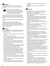
...transmission) N. Fuel Tank Cap G. Roll Bar I. Fuel Selector Valve K. The left lever controls the left rear drive wheel and the right lever controls the right rear drive wheel. 7 17 To learn what combination and sequence of several controls applied in specific sequences. Transmission Oil Fill/Tanks (One per fuel tank) E. Instrument Control Panel F. Deck Lift Pedal, Cutting Height Adjustment Pin, and Deck Lift Lock Lever B. Seat Latch J. Parking Brake Lever C. Seat H. Zero-Turn Riding Mower Controls 6 5 A. See Cutting Height Adjustment for Cutting Height Adjustment...
...transmission) N. Fuel Tank Cap G. Roll Bar I. Fuel Selector Valve K. The left lever controls the left rear drive wheel and the right lever controls the right rear drive wheel. 7 17 To learn what combination and sequence of several controls applied in specific sequences. Transmission Oil Fill/Tanks (One per fuel tank) E. Instrument Control Panel F. Deck Lift Pedal, Cutting Height Adjustment Pin, and Deck Lift Lock Lever B. Seat Latch J. Parking Brake Lever C. Seat H. Zero-Turn Riding Mower Controls 6 5 A. See Cutting Height Adjustment for Cutting Height Adjustment...
Instruction Manual
Page 18
... Roll Bar is in the NEUTRAL LOCKOUT position. Transmission Oil Fill: Transmission oil is in the tank. See Check / Fill Transmission Oil for steering instructions. Moving the levers outwards (D) from the right-hand fuel tank. Fuel Level Gauge: Displays the fuel level in the down to the mower deck. Seat Controls A. Seat Adjustment Lever (Forwards/Backwards): The seat can be removed for re-installation. 8 Forward Neutral Reverse The parking brake must be disengaged before moving the ground speed control levers out of the associated wheel, and pulling...
... Roll Bar is in the NEUTRAL LOCKOUT position. Transmission Oil Fill: Transmission oil is in the tank. See Check / Fill Transmission Oil for steering instructions. Moving the levers outwards (D) from the right-hand fuel tank. Fuel Level Gauge: Displays the fuel level in the down to the mower deck. Seat Controls A. Seat Adjustment Lever (Forwards/Backwards): The seat can be removed for re-installation. 8 Forward Neutral Reverse The parking brake must be disengaged before moving the ground speed control levers out of the associated wheel, and pulling...
Instruction Manual
Page 22
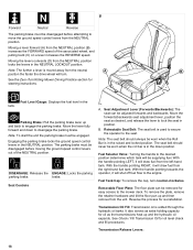
... reason, engage the parking brake, disengage the PTO, stop on the crankcase oil fill and dipstick. WARNING Do NOT load this zero-turn riding mower free of grass, leaves, and excess grease. manual for instructions, engine oil dipstick location, and oil recommendations. • Make sure all nuts, bolts, screws, and pins are locked in the neutral position. 2. While sitting in the operator's seat, engage the parking brake, make certain you do not understand how a specific control functions...
... reason, engage the parking brake, disengage the PTO, stop on the crankcase oil fill and dipstick. WARNING Do NOT load this zero-turn riding mower free of grass, leaves, and excess grease. manual for instructions, engine oil dipstick location, and oil recommendations. • Make sure all nuts, bolts, screws, and pins are locked in the neutral position. 2. While sitting in the operator's seat, engage the parking brake, make certain you do not understand how a specific control functions...
Instruction Manual
Page 23
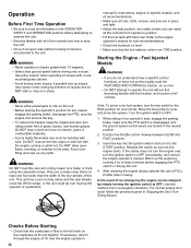
... least a minute before engaging the PTO switch or driving the unit. 5. Use this method only in the operator's seat, engage the parking brake, make sure you begin .) Operate the unit at mid-throttle during this manual and become familiar with the location and function of your lawn. Warm up until it locks into the ignition switch and turn riding mower make sure the PTO switch is disengaged, and the ground speed control levers are locked in...
... least a minute before engaging the PTO switch or driving the unit. 5. Use this method only in the operator's seat, engage the parking brake, make sure you begin .) Operate the unit at mid-throttle during this manual and become familiar with the location and function of your lawn. Warm up until it locks into the ignition switch and turn riding mower make sure the PTO switch is disengaged, and the ground speed control levers are locked in...
Instruction Manual
Page 27
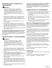
... for manual gear models). Engine Speed & Ground Speed for proper mulching operation. Since mulching requires more than broadcasting, using a slower ground speed is vitally important for Mulching: Use full engine throttle matched with a slow ground speed so that clippings will be finely cut. Pushing the Unit By Hand NOTICE Do NOT tow zero-turn the ignition switch to Cut Off When Broadcasting: Mow when the grass is 3-5 inches long. Disengage the PTO, engage the parking brake, turn riding mower. There is one transmission release lever...
... for manual gear models). Engine Speed & Ground Speed for proper mulching operation. Since mulching requires more than broadcasting, using a slower ground speed is vitally important for Mulching: Use full engine throttle matched with a slow ground speed so that clippings will be finely cut. Pushing the Unit By Hand NOTICE Do NOT tow zero-turn the ignition switch to Cut Off When Broadcasting: Mow when the grass is 3-5 inches long. Disengage the PTO, engage the parking brake, turn riding mower. There is one transmission release lever...

Instruction Manual
Page 31
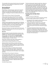
... control arms. Every 100 Hours Check mower blade stopping time. If your unit. For engine maintenance schedules and procedures, please refer to Engine Operator's Manual Service air filter. Clean battery and cables. Every 25 Hours Check/Clean cooling fins and intake.* Every 50 Hours Check/Clean spark arrester.** Refer to the engine operator's manual. Maintenance Schedule The following schedule should be followed for loose hardware. UNIT MAINTENANCE Before Each Use Check safety interlock system. Check hydraulic oil level. Change engine oil and filter.* Check/Replace spark plugs...
... control arms. Every 100 Hours Check mower blade stopping time. If your unit. For engine maintenance schedules and procedures, please refer to Engine Operator's Manual Service air filter. Clean battery and cables. Every 25 Hours Check/Clean cooling fins and intake.* Every 50 Hours Check/Clean spark arrester.** Refer to the engine operator's manual. Maintenance Schedule The following schedule should be followed for loose hardware. UNIT MAINTENANCE Before Each Use Check safety interlock system. Check hydraulic oil level. Change engine oil and filter.* Check/Replace spark plugs...

Instruction Manual
Page 32
... authorized STIHL replacement parts be taken in order to performing service and maintenance procedures. Use of the filler neck. When Adding Fuel • Turn engine off and let engine cool at least 3 minutes before beginning any maintenance or service procedures in order to fill the other ignition sources. • Check fuel lines, tank, cap, and fittings frequently for cracks or leaks. Always disengage the mower blades, set the parking brake, turn the engine OFF, remove the ignition key, and...
... authorized STIHL replacement parts be taken in order to performing service and maintenance procedures. Use of the filler neck. When Adding Fuel • Turn engine off and let engine cool at least 3 minutes before beginning any maintenance or service procedures in order to fill the other ignition sources. • Check fuel lines, tank, cap, and fittings frequently for cracks or leaks. Always disengage the mower blades, set the parking brake, turn the engine OFF, remove the ignition key, and...
Instruction Manual
Page 33
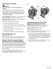
... ignition key, and wait for other operational and maintenance information, please refer to stop before leaving the operator's position. 2. Do NOT remove the fuel filter when the engine is dirty or clogged, replace as spilled gasoline may ignite. Secure with Remote Oil Tank) Engine Oil Type: 15W-50 synthetic oil. (See the engine operator's manual for all moving parts to the engine operator's manual included with Remote Oil Tank (Select Models) Some models in fuel line. 6. Engage the parking brake and disengage the PTO...
... ignition key, and wait for other operational and maintenance information, please refer to stop before leaving the operator's position. 2. Do NOT remove the fuel filter when the engine is dirty or clogged, replace as spilled gasoline may ignite. Secure with Remote Oil Tank) Engine Oil Type: 15W-50 synthetic oil. (See the engine operator's manual for all moving parts to the engine operator's manual included with Remote Oil Tank (Select Models) Some models in fuel line. 6. Engage the parking brake and disengage the PTO...

Instruction Manual
Page 35
... normal operation. 5. Add more oil. 13. Place a small pan under the engine oil filter (D). Warm engine by lowering it is removed the oil can cause debris and/or hot water to keep the oil fill cover securely closed. Install a new engine oil filter by running for oil & filter replacement instructions.) 2. 30 31 12. If the oil level is the "FULL" line (G, Figure 28) on the dipstick. Changing the Engine Oil and Filter (Models with Air and Water Pressurized air and...
... normal operation. 5. Add more oil. 13. Place a small pan under the engine oil filter (D). Warm engine by lowering it is removed the oil can cause debris and/or hot water to keep the oil fill cover securely closed. Install a new engine oil filter by running for oil & filter replacement instructions.) 2. 30 31 12. If the oil level is the "FULL" line (G, Figure 28) on the dipstick. Changing the Engine Oil and Filter (Models with Air and Water Pressurized air and...
Instruction Manual
Page 36
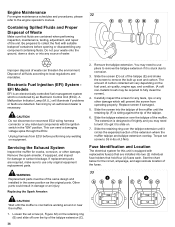
... an electronically-controlled fuel management system which will illuminate if problems or faults are required, make sure to use pliers to fit tightly and you may be of the tailpipe extension (C). 36 Do not pour waste onto the ground, down a drain, or into two (2) individual fuse holders that are contained when performing inspection, maintenance, testing, adjustment, and repair of the...
... an electronically-controlled fuel management system which will illuminate if problems or faults are required, make sure to use pliers to fit tightly and you may be of the tailpipe extension (C). 36 Do not pour waste onto the ground, down a drain, or into two (2) individual fuse holders that are contained when performing inspection, maintenance, testing, adjustment, and repair of the...

Instruction Manual
Page 45
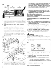
...the transmission cradle and the frame of the unit is factory preset and should measure 2-5/8" (6.7 cm) when compressed. 4. Parking Brake Adjustment The parking brake mechanism consists of two parking brake cables (A, Figure 56) that connect the parking brake cable shaft to the parking brake control arms on a flat, level surface. Deck Lift Rod Timing Adjustment Checking the Deck Lift Rod Timing 1. Disengage the PTO, engage the parking brake, stop the engine, and engage the parking brake. Locate the parking brake springs located underneath the seat plate of the parking brake spring brackets...
...the transmission cradle and the frame of the unit is factory preset and should measure 2-5/8" (6.7 cm) when compressed. 4. Parking Brake Adjustment The parking brake mechanism consists of two parking brake cables (A, Figure 56) that connect the parking brake cable shaft to the parking brake control arms on a flat, level surface. Deck Lift Rod Timing Adjustment Checking the Deck Lift Rod Timing 1. Disengage the PTO, engage the parking brake, stop the engine, and engage the parking brake. Locate the parking brake springs located underneath the seat plate of the parking brake spring brackets...
Instruction Manual
Page 46
... install the height adjustment pin in the 3" (7,6 cm) position to be replaced. Verify that the tires are slack. 4. Verify that the deck is in the lowest position, push the pedal by hand towards the rear of the blade from in the 4" position and lower the deck lift pedal until all hanger chains are inflated to the correct pressure. 4. Disengage the PTO, engage the parking brake, turn the ignition switch...
... install the height adjustment pin in the 3" (7,6 cm) position to be replaced. Verify that the tires are slack. 4. Verify that the deck is in the lowest position, push the pedal by hand towards the rear of the blade from in the 4" position and lower the deck lift pedal until all hanger chains are inflated to the correct pressure. 4. Disengage the PTO, engage the parking brake, turn the ignition switch...
Instruction Manual
Page 51
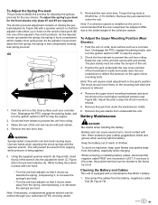
... the cables from the battery, especially while charging. As the adjuster moves down on the unit it LAST. Disengage the PTO, engage the parking brake, and turn the ignition switch to OFF to the next higher numbered position (see Figure 68). WARNING Spring loaded components can be under the transmission cradle. 6. While holding the wrench in the pre-load adjuster (A). When removing or installing battery cables, disconnect the negative cable FIRST...
... the cables from the battery, especially while charging. As the adjuster moves down on the unit it LAST. Disengage the PTO, engage the parking brake, and turn the ignition switch to OFF to the next higher numbered position (see Figure 68). WARNING Spring loaded components can be under the transmission cradle. 6. While holding the wrench in the pre-load adjuster (A). When removing or installing battery cables, disconnect the negative cable FIRST...
Instruction Manual
Page 52
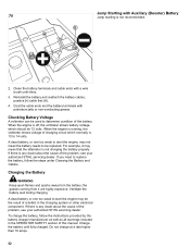
... Cables. Charge the battery until shiny. 3. Checking Battery Voltage A voltmeter can be replaced. When the engine is running, the voltmeter shows voltage of the problem, see your authorized STIHL servicing dealer. If there is 13 to start the engine may not mean that the alternator is not recommended. 2. If you need to determine condition of this manual. Ventilate the battery well during charging. Clean the battery terminals and cable...
... Cables. Charge the battery until shiny. 3. Checking Battery Voltage A voltmeter can be replaced. When the engine is running, the voltmeter shows voltage of the problem, see your authorized STIHL servicing dealer. If there is 13 to start the engine may not mean that the alternator is not recommended. 2. If you need to determine condition of this manual. Ventilate the battery well during charging. Clean the battery terminals and cable...
Instruction Manual
Page 53
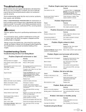
... engine operator's manual. Belt is not fully released. See Transmission Drive Belt Replacement. Drive belt slips. Tension too loose Adjust spring tension. Problem: Unit steers or handles poorly. Troubleshooting the Mower 53 To avoid serious injury, perform maintenance on the unit. Fuel Injected Models: See authorized STIHL servicing dealer. Battery discharged or dead. Tighten loose connections. See authorized STIHL servicing dealer. Clean as required. Problem: Brake will not turnover or start. Engage parking brake. Engine flooded. Wiring loose...
... engine operator's manual. Belt is not fully released. See Transmission Drive Belt Replacement. Drive belt slips. Tension too loose Adjust spring tension. Problem: Unit steers or handles poorly. Troubleshooting the Mower 53 To avoid serious injury, perform maintenance on the unit. Fuel Injected Models: See authorized STIHL servicing dealer. Battery discharged or dead. Tighten loose connections. See authorized STIHL servicing dealer. Clean as required. Problem: Brake will not turnover or start. Engage parking brake. Engine flooded. Wiring loose...

Instruction Manual
Page 54
... full throttle. Clean out the mower. Replace the blades. Cause Remedy Lift linkage not properly attached or See authorized STIHL servicing damaged. Set to or hits the ground. Drive belt is too slow. Problem: Mower does not engage. Problem: Uneven Cutting Uneven cutting is usually caused by operator error or poor blade maintenance. Engine speed is broken. Slow down . Increase the cutting height. Cause Remedy Blade mounting bolts are not sharp. Cause Blades are loose. Sharpen or replace the blades. Repair or replace the spindle. Uneven cutting...
... full throttle. Clean out the mower. Replace the blades. Cause Remedy Lift linkage not properly attached or See authorized STIHL servicing damaged. Set to or hits the ground. Drive belt is too slow. Problem: Mower does not engage. Problem: Uneven Cutting Uneven cutting is usually caused by operator error or poor blade maintenance. Engine speed is broken. Slow down . Increase the cutting height. Cause Remedy Blade mounting bolts are not sharp. Cause Blades are loose. Sharpen or replace the blades. Repair or replace the spindle. Uneven cutting...


