
TL-SG3428XFUN V1.6 Installation Guide
Page 3
... on Download Center. The note contains the helpful information for a better use of the switch. Related Document The User Guide and CLI Reference Guide of client limitations and environmental factors. • This guide uses the specific formats to configure the switch. The following table lists the notice icons that should be attended to during the installation. Appendix A Troubleshooting Appendix B Hardware Specifications Audience This Installation Guide is for demonstration purposes only. Actual PoE power budget...
... on Download Center. The note contains the helpful information for a better use of the switch. Related Document The User Guide and CLI Reference Guide of client limitations and environmental factors. • This guide uses the specific formats to configure the switch. The following table lists the notice icons that should be attended to during the installation. Appendix A Troubleshooting Appendix B Hardware Specifications Audience This Installation Guide is for demonstration purposes only. Actual PoE power budget...
TL-SG3428XFUN V1.6 Installation Guide
Page 5
.... Link aggregation (LACP) increases aggregated bandwidth, optimizing the transport of networks. TL-SX3206HPP/ TL-SG3210XHP-M2/ TL-SG3218XP-M2/ TL-SG3428MP/ TL-SG3428XMP/ TLSG3428XPP-M2/TL-SG3452P/TL-SG3452XP is friendly to manage, which can fully meet the need of TL-SX3206HPP is shown as the following figure. LED Console Port SFP+ Slot (RJ45/USB) Introduction 01 SNMP, RMON, WEB and CLI Login bring abundant management policies. Examples include powering network cameras, wireless LAN access points, IP telephones, network hubs...
.... Link aggregation (LACP) increases aggregated bandwidth, optimizing the transport of networks. TL-SX3206HPP/ TL-SG3210XHP-M2/ TL-SG3218XP-M2/ TL-SG3428MP/ TL-SG3428XMP/ TLSG3428XPP-M2/TL-SG3452P/TL-SG3452XP is friendly to manage, which can fully meet the need of TL-SX3206HPP is shown as the following figure. LED Console Port SFP+ Slot (RJ45/USB) Introduction 01 SNMP, RMON, WEB and CLI Login bring abundant management policies. Examples include powering network cameras, wireless LAN access points, IP telephones, network hubs...
TL-SG3428XFUN V1.6 Installation Guide
Page 6
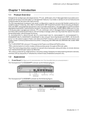
.... LED Console Port 2.5G SFP+ Slot (RJ45/USB) RJ45 Port The front panel of TL-SG3218XP-M2 is shown as the following figure. LED Console Port 2.5G SFP+ Slot (RJ45/USB) RJ45 Port The front panel of TL-SG3428 is shown as the foRllJo4w5inPgorftigure. JetStream L2/L2+ Managed Switch 1G The front panel of TL-SX3016F is shown as the following figure. 24-Port Gigabit L2+ Managed Switch with 4 SFP Slots LED Console Port (USB/RJ45...
.... LED Console Port 2.5G SFP+ Slot (RJ45/USB) RJ45 Port The front panel of TL-SG3218XP-M2 is shown as the following figure. LED Console Port 2.5G SFP+ Slot (RJ45/USB) RJ45 Port The front panel of TL-SG3428 is shown as the foRllJo4w5inPgorftigure. JetStream L2/L2+ Managed Switch 1G The front panel of TL-SX3016F is shown as the following figure. 24-Port Gigabit L2+ Managed Switch with 4 SFP Slots LED Console Port (USB/RJ45...
TL-SG3428XFUN V1.6 Installation Guide
Page 8
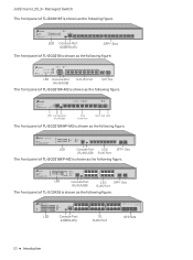
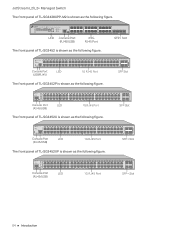
.... TL-SG3452XP PWR PoE Max SYS FAN Speed PoE L2+ Managed PoE+ Switch Console(RJ45) Console(USB) Console Port (RJ45/USB) LED 1000Mbps 10/100Mbps Speed activity Delivering Power Over Budget PoE Fault 1G RJ45 Port F SFP Slot F SFP Slot 10Gbps 1Gbps SFP+ activity SFP+ Slot 10Gbps 1Gbps SFP+ activity SFP+ Slot 04 Introduction JetStream L2/L2+ Managed Switch The front panel of TL-SG3428XPP-M2 is shown as the following figure. TL-SG3452P Managed PoE+ Switch PWR PoE Max SYS FAN Speed PoE Console(RJ45) Console(USB) Console Port (RJ45/USB) LED...
.... TL-SG3452XP PWR PoE Max SYS FAN Speed PoE L2+ Managed PoE+ Switch Console(RJ45) Console(USB) Console Port (RJ45/USB) LED 1000Mbps 10/100Mbps Speed activity Delivering Power Over Budget PoE Fault 1G RJ45 Port F SFP Slot F SFP Slot 10Gbps 1Gbps SFP+ activity SFP+ Slot 10Gbps 1Gbps SFP+ activity SFP+ Slot 04 Introduction JetStream L2/L2+ Managed Switch The front panel of TL-SG3428XPP-M2 is shown as the following figure. TL-SG3452P Managed PoE+ Switch PWR PoE Max SYS FAN Speed PoE Console(RJ45) Console(USB) Console Port (RJ45/USB) LED...
TL-SG3428XFUN V1.6 Installation Guide
Page 9
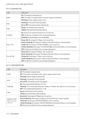
... receiving data. Off: No device is linked to the corresponding port. Flashing: Power supply is supplying power normally. Green On: The port is abnormal. On or Off: The switch works improperly. Off: No device is linked to the corresponding port. Yellow On: Running at 10 Gbps, but no activity. Off: The switch is powered off or power supply is abnormal. JetStream L2/L2+ Managed Switch LEDs For TL-SX3206HPP LED PWR SYS PoE Max FAN Speed PoE SFP...
... receiving data. Off: No device is linked to the corresponding port. Flashing: Power supply is supplying power normally. Green On: The port is abnormal. On or Off: The switch works improperly. Off: No device is linked to the corresponding port. Yellow On: Running at 10 Gbps, but no activity. Off: The switch is powered off or power supply is abnormal. JetStream L2/L2+ Managed Switch LEDs For TL-SX3206HPP LED PWR SYS PoE Max FAN Speed PoE SFP...
TL-SG3428XFUN V1.6 Installation Guide
Page 10
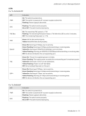
... 1 Gbps and transmitting or receiving data. For TL-SG3210X-M2 LED PWR SYS Indication On: The switch is powered by PWR2. Flashing: The switch works properly. Yellow Flashing: Running at 1 Gbps and transmitting or receiving data. The switch is powered on. Off: No device is linked to go out after PWR2 is abnormal. Flashing: Power supply is unplugged. JetStream L2/L2+ Managed Switch LED Port 1-8 Indication Green On: Running at 1 Gbps...
... 1 Gbps and transmitting or receiving data. For TL-SG3210X-M2 LED PWR SYS Indication On: The switch is powered by PWR2. Flashing: The switch works properly. Yellow Flashing: Running at 1 Gbps and transmitting or receiving data. The switch is powered on. Off: No device is linked to go out after PWR2 is abnormal. Flashing: Power supply is unplugged. JetStream L2/L2+ Managed Switch LED Port 1-8 Indication Green On: Running at 1 Gbps...
TL-SG3428XFUN V1.6 Installation Guide
Page 11
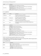
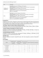
... the fans work properly. Yellow Flashing: Power-on the port. Green Flashing: Running at 1 Gbps and transmitting or receiving data. Yellow Flashing: Running at 100 Mbps, but no activity. For TL-SG3210XHP-M2 LED PWR SYS PoE Max FAN Speed PoE Indication On: The switch is ≤ 7 W. On or Off: The switch works improperly. On: The remaining PoE power is powered on for 2 minutes. Green On: The port is linked to the corresponding port. Yellow...
... the fans work properly. Yellow Flashing: Power-on the port. Green Flashing: Running at 1 Gbps and transmitting or receiving data. Yellow Flashing: Running at 100 Mbps, but no activity. For TL-SG3210XHP-M2 LED PWR SYS PoE Max FAN Speed PoE Indication On: The switch is ≤ 7 W. On or Off: The switch works improperly. On: The remaining PoE power is powered on for 2 minutes. Green On: The port is linked to the corresponding port. Yellow...
TL-SG3428XFUN V1.6 Installation Guide
Page 12
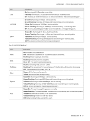
...+ Managed Switch LED Port 9-10 Indication Green On: Running at 1 Gbps and transmitting or receiving data. Off: No device is linked to the corresponding port. Green On: The port is ≤ 7 W. Yellow On: Overload or short circuit is > 7 W. Off: Not providing PoE power on self-test failed. Yellow Flashing: Running at 1 Gbps, but no activity. Yellow: Not all the fans work properly. Off: The remaining PoE power is...
...+ Managed Switch LED Port 9-10 Indication Green On: Running at 1 Gbps and transmitting or receiving data. Off: No device is linked to the corresponding port. Green On: The port is ≤ 7 W. Yellow On: Overload or short circuit is > 7 W. Off: Not providing PoE power on self-test failed. Yellow Flashing: Running at 1 Gbps, but no activity. Yellow: Not all the fans work properly. Off: The remaining PoE power is...

TL-SG3428XFUN V1.6 Installation Guide
Page 15
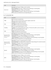
... at 1 Gbps and transmitting or receiving data. For TL-SG3428XF PWR1* Green On Green On Off Off PWR2 Off Yellow On** Green On Off Indication The switch is the primary power supply and it takes 10-20 seconds for the LED PWR2 (yellow) to the port but no activity. Yellow: Not all the fans work properly. Green Flashing: Running at 100 Mbps and transmitting or...
... at 1 Gbps and transmitting or receiving data. For TL-SG3428XF PWR1* Green On Green On Off Off PWR2 Off Yellow On** Green On Off Indication The switch is the primary power supply and it takes 10-20 seconds for the LED PWR2 (yellow) to the port but no activity. Yellow: Not all the fans work properly. Green Flashing: Running at 100 Mbps and transmitting or...
TL-SG3428XFUN V1.6 Installation Guide
Page 16
JetStream L2/L2+ Managed Switch For TL-SG3428X-M2 LED PWR SYS FAN Link/Act Port 1-24 Port 25-28 Indication On: The switch is powered on . Flashing: Power supply is abnormal. Green On: Running at 10/100/1000Mbp, but no activity. Yellow On: Running at 2.5 Gbps, but no activity. Yellow Flashing: Running at 2.5 Gbps and transmitting or receiving data. Yellow On: Running at 10/100/1000Mbps...
JetStream L2/L2+ Managed Switch For TL-SG3428X-M2 LED PWR SYS FAN Link/Act Port 1-24 Port 25-28 Indication On: The switch is powered on . Flashing: Power supply is abnormal. Green On: Running at 10/100/1000Mbp, but no activity. Yellow On: Running at 2.5 Gbps, but no activity. Yellow Flashing: Running at 2.5 Gbps and transmitting or receiving data. Yellow On: Running at 10/100/1000Mbps...
TL-SG3428XFUN V1.6 Installation Guide
Page 18
...: For TL-SG3428XMP/TL-SG3452XP Console Port Designed to the corresponding port. Off: No device is linked to install the 1 Gbps SFP module. Green Flashing: Running at 1 Gbps, but no activity. For PoE switches, the port can also provide power for PDs. 10 Mbps/100 Mbps/1000 Mbps/2.5 Gbps RJ45 Port Designed to connect to install the 10 Gbps SFP+ module. SFP+ slot is active on only one console port at a time. Yellow On...
...: For TL-SG3428XMP/TL-SG3452XP Console Port Designed to the corresponding port. Off: No device is linked to install the 1 Gbps SFP module. Green Flashing: Running at 1 Gbps, but no activity. For PoE switches, the port can also provide power for PDs. 10 Mbps/100 Mbps/1000 Mbps/2.5 Gbps RJ45 Port Designed to connect to install the 10 Gbps SFP+ module. SFP+ slot is active on only one console port at a time. Yellow On...
TL-SG3428XFUN V1.6 Installation Guide
Page 19
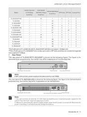
The rear panel of TL-SX3016F/TL-SG3428XF is shown as the following figure. Battery is automatically used to negotiate with a speed of 10 Mbps. ■ Rear Panel The rear panel of TL-SG3428X-UPS is shown as a redundant power supply for the switch. You can connect an external 12 V DC lead-acid battery as the following figure. Introduction 15 Kensington...
The rear panel of TL-SX3016F/TL-SG3428XF is shown as the following figure. Battery is automatically used to negotiate with a speed of 10 Mbps. ■ Rear Panel The rear panel of TL-SG3428X-UPS is shown as a redundant power supply for the switch. You can connect an external 12 V DC lead-acid battery as the following figure. Introduction 15 Kensington...

TL-SG3428XFUN V1.6 Installation Guide
Page 20
... Documents: https://www.tp-link.com/us/configuration-guides/lightning_protection_guide/. Make sure that the voltage of the power supply meets the requirement of your switch and go to the product Support web page, refer to prevent the device from the depicted. Caution: Please use the provided power cord. 16 Introduction Your switch may differ in appearance from being stolen. Grounding Terminal The switch already comes with Ground Cable...
... Documents: https://www.tp-link.com/us/configuration-guides/lightning_protection_guide/. Make sure that the voltage of the power supply meets the requirement of your switch and go to the product Support web page, refer to prevent the device from the depicted. Caution: Please use the provided power cord. 16 Introduction Your switch may differ in appearance from being stolen. Grounding Terminal The switch already comes with Ground Cable...
TL-SG3428XFUN V1.6 Installation Guide
Page 23
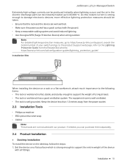
... Guide from the power socket. 2.3 Installation Tools ■ Phillips screwdriver ■ ESD-preventive wrist wrap ■ Cables Note: These tools are well earthed. ■ Make sure the power socket has a good contact with all fittings. Note: For detailed lightning protection measures, go to https://www.tp-link.com/support, search the model number of your switch and go to the product Support web page, refer...
... Guide from the power socket. 2.3 Installation Tools ■ Phillips screwdriver ■ ESD-preventive wrist wrap ■ Cables Note: These tools are well earthed. ■ Make sure the power socket has a good contact with all fittings. Note: For detailed lightning protection measures, go to https://www.tp-link.com/support, search the model number of your switch and go to the product Support web page, refer...
TL-SG3428XFUN V1.6 Installation Guide
Page 27
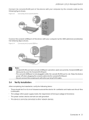
Figure 3-3 Connecting the Console (RJ45) Port Connect the console (USB) port of the device with other network devices. Keep the device power off when plugging the console cable into the console (RJ45) port. ■ Do not connect the console port with your computer by the USB cable (not provided) as the following figure shows. Connection 23 JetStream L2/L2+ Managed Switch Connect the console (RJ45) port of the device with your computer by the console cable as...
Figure 3-3 Connecting the Console (RJ45) Port Connect the console (USB) port of the device with other network devices. Keep the device power off when plugging the console cable into the console (RJ45) port. ■ Do not connect the console port with your computer by the USB cable (not provided) as the following figure shows. Connection 23 JetStream L2/L2+ Managed Switch Connect the console (RJ45) port of the device with your computer by the console cable as...
TL-SG3428XFUN V1.6 Installation Guide
Page 29
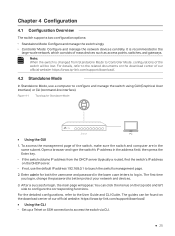
... as access points, switches, and gateways. Chapter 4 Configuration 4.1 Configuration Overview The switch supports two configuration options: ■ Standalone Mode: Configure and manage the switch singly. ■ Controller Mode: Configure and manage the network devices centrally. Figure 4-1 Topology for both the username and password in the large-scale network, which consists of our official website: https://www.tp-link.com/support/download/. ■ Using the CLI ■ Set up a Telnet or SSH connection to the User Guide and CLI Guide. The first time you log in the address field...
... as access points, switches, and gateways. Chapter 4 Configuration 4.1 Configuration Overview The switch supports two configuration options: ■ Standalone Mode: Configure and manage the switch singly. ■ Controller Mode: Configure and manage the network devices centrally. Figure 4-1 Topology for both the username and password in the large-scale network, which consists of our official website: https://www.tp-link.com/support/download/. ■ Using the CLI ■ Set up a Telnet or SSH connection to the User Guide and CLI Guide. The first time you log in the address field...
TL-SG3428XFUN V1.6 Installation Guide
Page 30
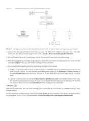
... of our official website: https://www.tp-link.com/download-center.html Note: For certain devices, you may need to change the password the first time you have no spare PC to the User Guide and CLI Guide. When using the console port, start the terminal emulation program (such as the Hyper Terminal) on the DHCP server. ■ Via Omada Hardware Controller (OC200/OC300) Omada Hardware Controller (OC200/OC300) is a good alternative...
... of our official website: https://www.tp-link.com/download-center.html Note: For certain devices, you may need to change the password the first time you have no spare PC to the User Guide and CLI Guide. When using the console port, start the terminal emulation program (such as the Hyper Terminal) on the DHCP server. ■ Via Omada Hardware Controller (OC200/OC300) Omada Hardware Controller (OC200/OC300) is a good alternative...
TL-SG3428XFUN V1.6 Installation Guide
Page 31
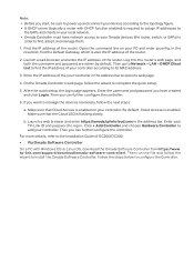
... the quick setup. 5. Find the IP address of the router. Enter the username and password you have network access to your Omada devices (the router, switch, or EAPs) in the address bar to open its MAC address. 3. If you want to configure the Controller. tp-link.com/support/download/omada-software-controller/. Log into the router's web page, and both the username and password are admin by default. Note: • Before you start, be sure to power up and connect your...
... the quick setup. 5. Find the IP address of the router. Enter the username and password you have network access to your Omada devices (the router, switch, or EAPs) in the address bar to open its MAC address. 3. If you want to configure the Controller. tp-link.com/support/download/omada-software-controller/. Log into the router's web page, and both the username and password are admin by default. Note: • Before you start, be sure to power up and connect your...
TL-SG3428XFUN V1.6 Installation Guide
Page 32
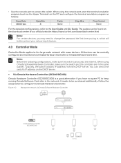
... a remote site via Omada Software/Hardware Controller Controller Omada Software Controller running on the Host PC Router Switch EAP EAP EAP Clients Note: To manage your devices, Omada Software Controller needs to keep running on the download center of our official website: https://www.tp-link.com/support/download/. b. A list of the controller. The guide can further configure the controller. 4. If not, click Launch a Browser to complete the quick setup. 3. Launch the Omada Software Controller on your controller...
... a remote site via Omada Software/Hardware Controller Controller Omada Software Controller running on the Host PC Router Switch EAP EAP EAP Clients Note: To manage your devices, Omada Software Controller needs to keep running on the download center of our official website: https://www.tp-link.com/support/download/. b. A list of the controller. The guide can further configure the controller. 4. If not, click Launch a Browser to complete the quick setup. 3. Launch the Omada Software Controller on your controller...
TL-SG3428XFUN V1.6 Installation Guide
Page 33
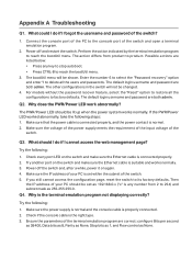
... sure the Ethernet cable is connected properly. 2. Appendix A Troubleshooting Q1. Enter the number 6 to select the "Password recovery" option and enter Y to delete all the configurations to the console port of the switch. The default login username and password are correct: configure Bits per second as 38400, Data bits as 8, Parity as None, Stop bits as 1, and Flow control as None. Q3. Power off and restart the switch. Make sure the power supply is...
... sure the Ethernet cable is connected properly. 2. Appendix A Troubleshooting Q1. Enter the number 6 to select the "Password recovery" option and enter Y to delete all the configurations to the console port of the switch. The default login username and password are correct: configure Bits per second as 38400, Data bits as 8, Parity as None, Stop bits as 1, and Flow control as None. Q3. Power off and restart the switch. Make sure the power supply is...


