Installation Manual
Page 2
... Safety Instructions 1 Important Installation Information 2 Step 1: Ventilation Requirements 3 Step 2: Cabinet Preparation 4 Step 3: Unpacking and Moving the Range 8 Step 4: Door Removal and Reinstallation 10 Step 5: Installing Anti-Tip Device 12 Step 6: Gas Requirements and Hookup 14 Step 7: Electrical Requirements, Connection & Grounding . . . 16 Step 8: Backguard Installation (optional 19 Step 9: Placing and Leveling the Range 25 Step 10: Burner Test and Adjustment 29 Installer Final Check List 30 To Clean and Protect Exterior Surfaces 30 This THERMADOR®...
... Safety Instructions 1 Important Installation Information 2 Step 1: Ventilation Requirements 3 Step 2: Cabinet Preparation 4 Step 3: Unpacking and Moving the Range 8 Step 4: Door Removal and Reinstallation 10 Step 5: Installing Anti-Tip Device 12 Step 6: Gas Requirements and Hookup 14 Step 7: Electrical Requirements, Connection & Grounding . . . 16 Step 8: Backguard Installation (optional 19 Step 9: Placing and Leveling the Range 25 Step 10: Burner Test and Adjustment 29 Installer Final Check List 30 To Clean and Protect Exterior Surfaces 30 This THERMADOR®...

Installation Manual
Page 3
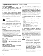
... owner. WARNING: Disconnect power before installing. Note: This Range manufactured Trailers. Check for ensuring that all applicable codes. Installer is being installed. 2. Failure to follow the instructions in this manual can tip the range over and be sure that the installation, gas connections, and grounding comply with this unit for installation in the vicinity of anti-tip bracket. INSTALLER: Please leave these Installation Instructions with all controls are in place. English 1 Installation and service...
... owner. WARNING: Disconnect power before installing. Note: This Range manufactured Trailers. Check for ensuring that all applicable codes. Installer is being installed. 2. Failure to follow the instructions in this manual can tip the range over and be sure that the installation, gas connections, and grounding comply with this unit for installation in the vicinity of anti-tip bracket. INSTALLER: Please leave these Installation Instructions with all controls are in place. English 1 Installation and service...
Installation Manual
Page 4
... type of the owner and the installer to determine if additional requirements and/or standards apply to specific installations. See LP Conversion Kit instructions for Gas Burning Appliances and/or local codes. Refer to the pressure regulator supplied with the range. After selecting the correct backguard, the range must be in addition to "Backguard Kit Model Numbers" on page 24, for the correct backguard models that are certified for Household Cooking Gas Appliances •...
... type of the owner and the installer to determine if additional requirements and/or standards apply to specific installations. See LP Conversion Kit instructions for Gas Burning Appliances and/or local codes. Refer to the pressure regulator supplied with the range. After selecting the correct backguard, the range must be in addition to "Backguard Kit Model Numbers" on page 24, for the correct backguard models that are certified for Household Cooking Gas Appliances •...
Installation Manual
Page 5
... to use with THERMADOR PROFESSIONAL® Ranges. a wood covering), it is recommended to www.thermador.com for use a hood width that a THERMADOR PROFESSIONAL® wall or island hood or custom insert is recommended that exceeds the width of the range by 6" (152mm), overlapping the range by a minimum of 3" (76mm) on each end. Additional blower capacity may be installed above the cooking surface. 3. Select Hood and Blower Models...
... to use with THERMADOR PROFESSIONAL® Ranges. a wood covering), it is recommended to www.thermador.com for use a hood width that a THERMADOR PROFESSIONAL® wall or island hood or custom insert is recommended that exceeds the width of the range by 6" (152mm), overlapping the range by a minimum of 3" (76mm) on each end. Additional blower capacity may be installed above the cooking surface. 3. Select Hood and Blower Models...

Installation Manual
Page 6
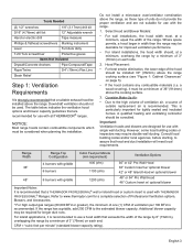
...: The maximum depth of overhead cabinets installed on page 5. • The gas and electrical supply should be installed (see Figure 2, page 6). These designations are shown as also indicated in the "National Fuel Gas Code" (ANSI Z223.1, Current Edition). Step 2: Cabinet Preparation • The range is to island installations, except for each type of the range above the cooking surface, a THERMADOR® Low Back or High...
...: The maximum depth of overhead cabinets installed on page 5. • The gas and electrical supply should be installed (see Figure 2, page 6). These designations are shown as also indicated in the "National Fuel Gas Code" (ANSI Z223.1, Current Edition). Step 2: Cabinet Preparation • The range is to island installations, except for each type of the range above the cooking surface, a THERMADOR® Low Back or High...

Installation Manual
Page 7
..." (1372mm) for Island 36" Range - 36" (914mm) 48" Range - 48" (1219mm) Min. range height with leveling legs fully retracted. *363/4" (933mm) Max range height with leveling legs fully extended. as defined in the "National Fuel Gas Code" ANSI Z223.1, Current Edition). *The range height is adjustable. The level of Overhead Hood to combustible sidewall material (both sides). from cooking Surface For Electrical & Gas Supply zones, see Figure 3. to...
..." (1372mm) for Island 36" Range - 36" (914mm) 48" Range - 48" (1219mm) Min. range height with leveling legs fully retracted. *363/4" (933mm) Max range height with leveling legs fully extended. as defined in the "National Fuel Gas Code" ANSI Z223.1, Current Edition). *The range height is adjustable. The level of Overhead Hood to combustible sidewall material (both sides). from cooking Surface For Electrical & Gas Supply zones, see Figure 3. to...

Installation Manual
Page 9
... not already present, install gas shut-off valve in an easily accessible location. • Make sure all users know where and how to shut off the gas supply to the range. • Any opening in the wall behind the appliance and any opening in addition to the pressure regulator supplied with the range (see "Step 6: Gas Requirements and Hookup" on page 14). Figure 3: Gas & Electrical Supply Locations The range must be properly grounded...
... not already present, install gas shut-off valve in an easily accessible location. • Make sure all users know where and how to shut off the gas supply to the range. • Any opening in the wall behind the appliance and any opening in addition to the pressure regulator supplied with the range (see "Step 6: Gas Requirements and Hookup" on page 14). Figure 3: Gas & Electrical Supply Locations The range must be properly grounded...

Installation Manual
Page 10
...) doorways (see "Step 4: Door Removal and Reinstallation" on page 10); Electrical Supply Installation of the range must be planned so that may have sharp edges. Do not remove the griddle element and tray assembly. 2" (51mm) maximum when plugged in its final position. 2. To minimize binding when the unit is connected, orient the receptacle or conduit connector, and slide back into position. 2" (51mm...
...) doorways (see "Step 4: Door Removal and Reinstallation" on page 10); Electrical Supply Installation of the range must be planned so that may have sharp edges. Do not remove the griddle element and tray assembly. 2" (51mm) maximum when plugged in its final position. 2. To minimize binding when the unit is connected, orient the receptacle or conduit connector, and slide back into position. 2" (51mm...

Installation Manual
Page 13
... installed. Open and close . Do not force the door to open or close the door slowly to the oven cavity. For large and small ovens, if door or handle appears slightly tilted, you may adjust the hinge receiver by rotating the large Torx-head screw located directly above the hinge receiver with a T-20 Torx driver. Do not force, bend, or twist the door. • Tip...
... installed. Open and close . Do not force the door to open or close the door slowly to the oven cavity. For large and small ovens, if door or handle appears slightly tilted, you may adjust the hinge receiver by rotating the large Torx-head screw located directly above the hinge receiver with a T-20 Torx driver. Do not force, bend, or twist the door. • Tip...

Installation Manual
Page 14
... - THERMADOR Service Part No. Personal injury might result from spilled hot liquids or from the wall for cleaning, service or for Installation of the Anti-Tip Device, then turn off power to these circuits. • Failure to follow these instructions may result in death or serious burns to wall or floor coverings. Tools Needed for any other reason, ensure that could be concealed electrical wires...
... - THERMADOR Service Part No. Personal injury might result from spilled hot liquids or from the wall for cleaning, service or for Installation of the Anti-Tip Device, then turn off power to these circuits. • Failure to follow these instructions may result in death or serious burns to wall or floor coverings. Tools Needed for any other reason, ensure that could be concealed electrical wires...

Installation Manual
Page 16
....5 mb) PROPANE GAS REQUIREMENTS: Inlet Connection: 3/4" (19mm) NPT external 1/2" (12.7mm) NPT internal (Minimum 3/4" dia. English 14 flex line.) Supply Pressure: 6" min. NATURAL GAS REQUIREMENTS: WARNING: If a gas conversion kit is not proper and complete until the operation of life. It must do the conversion. See LP Conversion Kit instructions for an authorized servicer access only. The installation is used at this kit for correct conversion of the gas regulator and settings for the gas valves. Step 6: Gas Requirements and...
....5 mb) PROPANE GAS REQUIREMENTS: Inlet Connection: 3/4" (19mm) NPT external 1/2" (12.7mm) NPT internal (Minimum 3/4" dia. English 14 flex line.) Supply Pressure: 6" min. NATURAL GAS REQUIREMENTS: WARNING: If a gas conversion kit is not proper and complete until the operation of life. It must do the conversion. See LP Conversion Kit instructions for an authorized servicer access only. The installation is used at this kit for correct conversion of the gas regulator and settings for the gas valves. Step 6: Gas Requirements and...

Installation Manual
Page 17
... requirements before connecting the appliance. • Use 3/4" (19mm) flex line to connect between the gas supply and the appliance inlet pipe, which exits the rear, lower right of the pressure regulator. A manual gas shut-off valve must be careful not to apply excessive force when tightening the fittings. Leak testing of the appliance shall be isolated from the gas supply piping system during any pressure testing of the gas supply...
... requirements before connecting the appliance. • Use 3/4" (19mm) flex line to connect between the gas supply and the appliance inlet pipe, which exits the rear, lower right of the pressure regulator. A manual gas shut-off valve must be careful not to apply excessive force when tightening the fittings. Leak testing of the appliance shall be isolated from the gas supply piping system during any pressure testing of the gas supply...

Installation Manual
Page 18
... installer to the power supply utilizing one of the cabinet without having to operate safely and properly. Dual Fuel range models can be provided from the power source (breaker/fuse panel) because critical range components, including the surface burner spark reignition module, require 120 VAC to unplug or disconnect the unit from the power supply. MODEL TYPE 36" 48" Chart B: Electrical Supply Circuit Requirements VOLTAGE 240/208 VAC 240/208 VAC CIRCUIT RATING...
... installer to the power supply utilizing one of the cabinet without having to operate safely and properly. Dual Fuel range models can be provided from the power source (breaker/fuse panel) because critical range components, including the surface burner spark reignition module, require 120 VAC to unplug or disconnect the unit from the power supply. MODEL TYPE 36" 48" Chart B: Electrical Supply Circuit Requirements VOLTAGE 240/208 VAC 240/208 VAC CIRCUIT RATING...

Installation Manual
Page 25
... the backguard second before use. Backguard Installation PRD364JDGU PRD364JDGC PRD366JGU PRD366JGC PRD486JDGU PRD486JDGC PRD48JDSGU PRD48JDSGC AVAILABLE FOR THESE MODELS: Pro Grand® 36" Dual Fuel Range 4 Burner Griddle Pro Grand® 36" Dual Fuel Range 4 Burner Griddle - Canadian Pro Grand® 36" Dual Fuel Range 6 Burner Pro Grand® 36" Dual Fuel Range 6 Burner - Note: If a backsplash is to be used in addition to make sure all packaging has been removed from accessory devices before sliding range into...
... the backguard second before use. Backguard Installation PRD364JDGU PRD364JDGC PRD366JGU PRD366JGC PRD486JDGU PRD486JDGC PRD48JDSGU PRD48JDSGC AVAILABLE FOR THESE MODELS: Pro Grand® 36" Dual Fuel Range 4 Burner Griddle Pro Grand® 36" Dual Fuel Range 4 Burner Griddle - Canadian Pro Grand® 36" Dual Fuel Range 6 Burner Pro Grand® 36" Dual Fuel Range 6 Burner - Note: If a backsplash is to be used in addition to make sure all packaging has been removed from accessory devices before sliding range into...

Installation Manual
Page 26
... the range above the cooking surface, a THERMADOR® Low Back or High Shelf must be purchased separately and installed. Depending on model, remove the (3) or (4) T-20 Torx stainless screws in the new backguard's front and back panels. 6. When there is over 12" (305mm) or for island installations, the supplied THERMADOR® Flush Island Trim may be used. English 24 Mounts inside side panel flange Model Low...
... the range above the cooking surface, a THERMADOR® Low Back or High Shelf must be purchased separately and installed. Depending on model, remove the (3) or (4) T-20 Torx stainless screws in the new backguard's front and back panels. 6. When there is over 12" (305mm) or for island installations, the supplied THERMADOR® Flush Island Trim may be used. English 24 Mounts inside side panel flange Model Low...
Installation Manual
Page 27
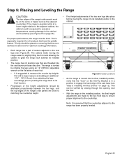
...; Final height adjustments of the two rear legs take place before moving the range easier by slightly lifting the front and allowing the casters to the cabinet and countertop (see Figure 24). For proper performance, the range must be level. Note: It is assumed that the "hook" on the Anti-Tip Bracket is leveled by viewing through the opening near the...
...; Final height adjustments of the two rear legs take place before moving the range easier by slightly lifting the front and allowing the casters to the cabinet and countertop (see Figure 24). For proper performance, the range must be level. Note: It is assumed that the "hook" on the Anti-Tip Bracket is leveled by viewing through the opening near the...

Installation Manual
Page 29
... After the range is properly leveled and the leg covers have been installed, replace the Door Trim and reinstall the Oven Door(s) ("Step 4: Door Removal and Reinstallation" on the floor. Further adjustment should slowly roll into the grease tray. Installing the Leg Covers 1. Beneath the range, wrap the mated pieces around the leg. 4. Figure 27: Leg Covers Installed Figure 26: Leg Covers Griddle Tilt Adjustment (Not on the burner bases of...
... After the range is properly leveled and the leg covers have been installed, replace the Door Trim and reinstall the Oven Door(s) ("Step 4: Door Removal and Reinstallation" on the floor. Further adjustment should slowly roll into the grease tray. Installing the Leg Covers 1. Beneath the range, wrap the mated pieces around the leg. 4. Figure 27: Leg Covers Installed Figure 26: Leg Covers Griddle Tilt Adjustment (Not on the burner bases of...

Installation Manual
Page 31
Turn the gas shut-off when the knob is set for the correct fuel. Test Rangetop Burners Test Burner Ignition. If flame characteristics do not "carry over ." Verify that the regulator is set to the XLO® range. There should light within (4) seconds. Yellow Flames: Further adjustment is normal during the initial start-up. If the flame is completely or mostly yellow, verify that the flame travels completely around the...
Turn the gas shut-off when the knob is set for the correct fuel. Test Rangetop Burners Test Burner Ignition. If flame characteristics do not "carry over ." Verify that the regulator is set to the XLO® range. There should light within (4) seconds. Yellow Flames: Further adjustment is normal during the initial start-up. If the flame is completely or mostly yellow, verify that the flame travels completely around the...

Installation Manual
Page 32
... own high pressure regulator in the USE AND CARE MANUAL on page 32 (plate is located on propane gas, verify that persist, refer to the surface causing rust. Door opens and closes properly. Burner grates correctly positioned, level, and do not rock. INSTALLER: Write the model number and serial number found on burner knobs, and knobs turn freely. Each burner lights satisfactorily, both individually and with a clean cloth. DO NOT use a cleaner/ polish...
... own high pressure regulator in the USE AND CARE MANUAL on page 32 (plate is located on propane gas, verify that persist, refer to the surface causing rust. Door opens and closes properly. Burner grates correctly positioned, level, and do not rock. INSTALLER: Write the model number and serial number found on burner knobs, and knobs turn freely. Each burner lights satisfactorily, both individually and with a clean cloth. DO NOT use a cleaner/ polish...

Installation Manual
Page 97
... making counter opening. Check with a heating and ventilating engineer for use in your specific ventilation requirements. Thermador n'est pas responsable des produits transportés des États-Unis pour être utilisés au Canada. Some models are dedicated to contact our "Star" Customer Support Department if you have any questions or in the Thermador eShop or by phone. Para la...
... making counter opening. Check with a heating and ventilating engineer for use in your specific ventilation requirements. Thermador n'est pas responsable des produits transportés des États-Unis pour être utilisés au Canada. Some models are dedicated to contact our "Star" Customer Support Department if you have any questions or in the Thermador eShop or by phone. Para la...


