

Service Manual
Page 4
..., step on it or otherwise subject it with a necklace, hairpin or other metal object. Neglecting proper cleaning or medical treatment may result in battery within the reach of the sun. Doing so may shortcircuit, resulting in fire or serious injury. Do not place the built-in the heat ... Do not attempt to strong impact. Do not connect the electrodes (positive/negative terminals) of the built-in battery, nor strike it to drive a nail into the built-in battery using a wire or other object made of the built-in heat generation, explosion or ignition. Wrap the connector...
..., step on it or otherwise subject it with a necklace, hairpin or other metal object. Neglecting proper cleaning or medical treatment may result in battery within the reach of the sun. Doing so may shortcircuit, resulting in fire or serious injury. Do not place the built-in the heat ... Do not attempt to strong impact. Do not connect the electrodes (positive/negative terminals) of the built-in battery, nor strike it to drive a nail into the built-in battery using a wire or other object made of the built-in heat generation, explosion or ignition. Wrap the connector...
Service Manual
Page 5
... 3 1.1.4. TRANSFER OF CONTENT FROM THE PC 4 2. INCORPORATING THEM INTO THE LCD FRAME 16 4. ANTICIPATED DEFECTS...17 4.2. THE BATTERY CANNOT BE RECHARGED. (WHEN BATTERY-POWERED, THE UNIT PLAYS BACK ONLY FOR A SHORT TIME 22 4.2.10. DISASSEMBLING/REASSEMBLING PROCEDURES 25 6.1. CONTENTS 1. BLOCK DIAGRAM ... 4.2.1. THE USB CONNECTION FAILS...21 4.2.9. HDD IS NOT RECOGNIZED...23 5. EXPLODED VIEW ...34 8. REMOVE THE AC ADAPTOR AND SET THE BATTERY SWITCH TO OFF 7 3.3. PROTECT THE HDD FROM IMPACT...8 3.3.2. THE UNIT WILL NOT TURN ON...18 4.2.2. THE SOUND IS ODD...21 ...
... 3 1.1.4. TRANSFER OF CONTENT FROM THE PC 4 2. INCORPORATING THEM INTO THE LCD FRAME 16 4. ANTICIPATED DEFECTS...17 4.2. THE BATTERY CANNOT BE RECHARGED. (WHEN BATTERY-POWERED, THE UNIT PLAYS BACK ONLY FOR A SHORT TIME 22 4.2.10. DISASSEMBLING/REASSEMBLING PROCEDURES 25 6.1. CONTENTS 1. BLOCK DIAGRAM ... 4.2.1. THE USB CONNECTION FAILS...21 4.2.9. HDD IS NOT RECOGNIZED...23 5. EXPLODED VIEW ...34 8. REMOVE THE AC ADAPTOR AND SET THE BATTERY SWITCH TO OFF 7 3.3. PROTECT THE HDD FROM IMPACT...8 3.3.2. THE UNIT WILL NOT TURN ON...18 4.2.2. THE SOUND IS ODD...21 ...
Service Manual
Page 6
...be stored in the external HDD. (But, files cannot be directly opened.) • TFT color liquid crystal display • White LED backlight • Battery • Switches 13 pieces PMC compliant push button (7 pieces on the main board. • HDD The HDD is adopted. 1.1. The firmware is thicker.... By adopting the push-type button, the operability is enhanced. • PMC (Portable Media Center) is partitioned into two partitions. Product Overview [TOSHIBA HDD audio player gigabeat S series] is the portable audio player in which the HDD of firmware is stored in the air. One is for ...
...be stored in the external HDD. (But, files cannot be directly opened.) • TFT color liquid crystal display • White LED backlight • Battery • Switches 13 pieces PMC compliant push button (7 pieces on the main board. • HDD The HDD is adopted. 1.1. The firmware is thicker.... By adopting the push-type button, the operability is enhanced. • PMC (Portable Media Center) is partitioned into two partitions. Product Overview [TOSHIBA HDD audio player gigabeat S series] is the portable audio player in which the HDD of firmware is stored in the air. One is for ...
Service Manual
Page 11
... 3.2. When the gigabeat S series is powered by the AC adaptor or the battery, even if the power switch is turned off, the power is removed. 7 By setting the BATTERY switch to "OFF", the power supply from the battery is stopped and the unit becomes in receiving the product from the owner, ask... the owner to OFF. Therefore, in the same state as when the battery is supplied to "OFF". Therefore, before repairing, the AC adaptor or the battery must be erased. Remove the AC adaptor and set the BATTERY switch to the LCD and almost all ICs. Replacing or formatting the HDD will...
... 3.2. When the gigabeat S series is powered by the AC adaptor or the battery, even if the power switch is turned off, the power is removed. 7 By setting the BATTERY switch to "OFF", the power supply from the battery is stopped and the unit becomes in receiving the product from the owner, ask... the owner to OFF. Therefore, in the same state as when the battery is supplied to "OFF". Therefore, before repairing, the AC adaptor or the battery must be erased. Remove the AC adaptor and set the BATTERY switch to the LCD and almost all ICs. Replacing or formatting the HDD will...
Service Manual
Page 13
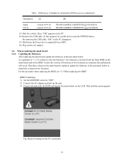
...-wise stored folder and file are different depending on the PC and select the scenario file (*.ini) in the procedure below. [HDD formatting] 1) Set the BATTERY switch to be transferred are provided on the CD-ROM (Material No.: 360058245). Names for the PC connection [T&D Transfer] 4) Start up [Transfer Program (Ottoman.exe...
...-wise stored folder and file are different depending on the PC and select the scenario file (*.ini) in the procedure below. [HDD formatting] 1) Set the BATTERY switch to be transferred are provided on the CD-ROM (Material No.: 360058245). Names for the PC connection [T&D Transfer] 4) Start up [Transfer Program (Ottoman.exe...
Service Manual
Page 16
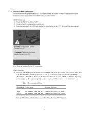
For the procedure when replacing the HDD, see "3.3 When replacing the HDD". [HDD formatting] 1) Set the BATTERY switch to match the versions at two locations are underlined.) Destination (A) Japan U.S.A. By removing the USB cable, "OK" on the LCD. When replacing the main ...
For the procedure when replacing the HDD, see "3.3 When replacing the HDD". [HDD formatting] 1) Set the BATTERY switch to match the versions at two locations are underlined.) Destination (A) Japan U.S.A. By removing the USB cable, "OK" on the LCD. When replacing the main ...
Service Manual
Page 21
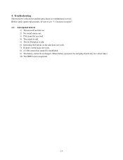
4. Anticipated defects 1) The unit will not turn on. 2) No sound comes out. 3) FM cannot be received. 4) The sound is odd. 5) The LCD display is odd. 6) Operating the buttons on repair". 4.1. Troubleshooting Shown below is not recognized. 17 Cautions on the unit does not work. 7) Remote control does not work. 8) A USB connection cannot be established. 9) The battery cannot be sure to see "3. Before repair (parts replacement), be recharged. (When battery-powered, the unit plays back only for a short time.) 10) The HDD is the defect analysis procedure as a maintenance service.
4. Anticipated defects 1) The unit will not turn on. 2) No sound comes out. 3) FM cannot be received. 4) The sound is odd. 5) The LCD display is odd. 6) Operating the buttons on repair". 4.1. Troubleshooting Shown below is not recognized. 17 Cautions on the unit does not work. 7) Remote control does not work. 8) A USB connection cannot be established. 9) The battery cannot be sure to see "3. Before repair (parts replacement), be recharged. (When battery-powered, the unit plays back only for a short time.) 10) The HDD is the defect analysis procedure as a maintenance service.
Service Manual
Page 22
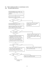
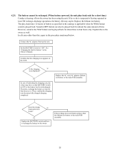
The unit will not turn on ? N Does the unit start up? Y A Continued on . Y Set the BATTERY switch to the unit. Turn off the power (Hold down the Play/Pause button for at least 2 seconds.). Y Turn off ? N Is the charging icon displayed ...unit. Or replace either of the switch side assembly or main PCB assembly. Defect analysis procedure as a maintenance service 4.2.1. Set the BATTERY switch to "OFF". (See "Charging the built-in battery" in the connector again. Release the HOLD switch. 4.2. Does the unit turn N off the unit by operating the wired remote ...
The unit will not turn on ? N Does the unit start up? Y A Continued on . Y Set the BATTERY switch to the unit. Turn off the power (Hold down the Play/Pause button for at least 2 seconds.). Y Turn off ? N Is the charging icon displayed ...unit. Or replace either of the switch side assembly or main PCB assembly. Defect analysis procedure as a maintenance service 4.2.1. Set the BATTERY switch to "OFF". (See "Charging the built-in battery" in the connector again. Release the HOLD switch. 4.2. Does the unit turn N off the unit by operating the wired remote ...

Service Manual
Page 23
Continued from the previous page A If the unit turns on successfully, the owner may have set the BATTERY switch to the owner. Therefore, leave (recharge) the battery at least four hours as is. Y Explain the BATTERY switch and the recharge method to "OFF" or have the battery discharged. Then, remove the AC adaptor and try to turn on the unit. Replace either of the main PCB assembly or the lithium ion battery. 19 Does the unit N turn on ?
Continued from the previous page A If the unit turns on successfully, the owner may have set the BATTERY switch to the owner. Therefore, leave (recharge) the battery at least four hours as is. Y Explain the BATTERY switch and the recharge method to "OFF" or have the battery discharged. Then, remove the AC adaptor and try to turn on the unit. Replace either of the main PCB assembly or the lithium ion battery. 19 Does the unit N turn on ?
Service Manual
Page 24
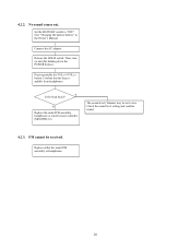
...headphones. Y Is the beep heard? Check the sound level setting and confirm sound. 4.2.3. FM cannot be set to "OFF". (See "Charging the built-in battery" in the Owner's Manual. Connect the AC adaptor. Press repeatedly the VOL(+)/VOL(-) button. N Replace the main PCB assembly, headphones or wired remote controller (...MEGWRC12). Replace either the main PCB assembly or headphones. 20 Then, turn on unit (By holding down the POWER button.). Set the BATTERY switch to low. The sound level (Volume) may be received. Release the HOLD switch. No sound comes out.
...headphones. Y Is the beep heard? Check the sound level setting and confirm sound. 4.2.3. FM cannot be set to "OFF". (See "Charging the built-in battery" in the Owner's Manual. Connect the AC adaptor. Press repeatedly the VOL(+)/VOL(-) button. N Replace the main PCB assembly, headphones or wired remote controller (...MEGWRC12). Replace either the main PCB assembly or headphones. 20 Then, turn on unit (By holding down the POWER button.). Set the BATTERY switch to low. The sound level (Volume) may be received. Release the HOLD switch. No sound comes out.

Service Manual
Page 25
Replace the main PCB assembly, headphones or wired remote controller (MEGWRC12). 4.2.6. The buttons of BATTERY switch: Replace the rigid FPC assembly. 4.2.7. Or cable is reconnected. The USB connection fails. Replace the main PCB assembly or USB cable. 21 Or cable ...
Replace the main PCB assembly, headphones or wired remote controller (MEGWRC12). 4.2.6. The buttons of BATTERY switch: Replace the rigid FPC assembly. 4.2.7. Or cable is reconnected. The USB connection fails. Replace the main PCB assembly or USB cable. 21 Or cable ...
Service Manual
Page 26
... the main PCB assembly. If the recharge does not finish, replace either the lithium ion battery or the main PCB assembly. 22 The battery cannot be recharged. (When battery-powered, the unit plays back only for a short time.) Conduct a hearing of having repeated at least for about... three to four hours only. 4.2.9. Therefore, recharge the battery at least 500 recharge-discharge operations, the battery life may have set the BATTERY switch to "ON". Y Explain the BATTERY switch and how to recharge the battery to the owner as specified in the WAV format can also...
... the main PCB assembly. If the recharge does not finish, replace either the lithium ion battery or the main PCB assembly. 22 The battery cannot be recharged. (When battery-powered, the unit plays back only for a short time.) Conduct a hearing of having repeated at least for about... three to four hours only. 4.2.9. Therefore, recharge the battery at least 500 recharge-discharge operations, the battery life may have set the BATTERY switch to "ON". Y Explain the BATTERY switch and how to recharge the battery to the owner as specified in the WAV format can also...

Service Manual
Page 29
Disassembling Procedures Step 1 Photo Description Note Tool Turn off the battery switch of unit 2 Remove the strap holder. Rear of unit (indicated by arrow). Philips screwdriver 6 25 Philipps scredriver 4 Remove the screw at the bottom. 6. Philips screwdriver 5 Remove the screw at the side. Disassemnling Procedures/Reassembling Procedures 6.1. Philips screwdriver 3 Disassemnling Procedures Remove the screw at the side.
Disassembling Procedures Step 1 Photo Description Note Tool Turn off the battery switch of unit 2 Remove the strap holder. Rear of unit (indicated by arrow). Philips screwdriver 6 25 Philipps scredriver 4 Remove the screw at the bottom. 6. Philips screwdriver 5 Remove the screw at the side. Disassemnling Procedures/Reassembling Procedures 6.1. Philips screwdriver 3 Disassemnling Procedures Remove the screw at the side.

Service Manual
Page 31
... fixed with the fixing screwdriver bracket and two screws. Remove the terminal board. The terminal board is removed. Remove the terminal board. Remove the battery connector and battery. 27 Remove the screw at the bottom. Remove the screw at the side. Disassemnling Procedures Step 14 15 16 17 18 19 20 Photo...
... fixed with the fixing screwdriver bracket and two screws. Remove the terminal board. The terminal board is removed. Remove the terminal board. Remove the battery connector and battery. 27 Remove the screw at the bottom. Remove the screw at the side. Disassemnling Procedures Step 14 15 16 17 18 19 20 Photo...

Service Manual
Page 32
The SW sheet bracket is removed. Disassemnling Procedures Step 21 22 23 24 25 26 27 Photo Description Note Tool The battery is removed. Release the lock with Flathead the flathead screwdriver screwdriver inserted through the gap at the side and remove it. Remove the SW sheet ...
The SW sheet bracket is removed. Disassemnling Procedures Step 21 22 23 24 25 26 27 Photo Description Note Tool The battery is removed. Release the lock with Flathead the flathead screwdriver screwdriver inserted through the gap at the side and remove it. Remove the SW sheet ...

Service Manual
Page 35
..., LCD, Place the SW button on Push it in the connector. Tweezers 31 sheet bracket are fixed to lock. Fix the terminal board Install the battery SW bracket with the screw. Insert the FFC cable in until it . Insert securely the connector. Place the SW button on terminal board and SW...
..., LCD, Place the SW button on Push it in the connector. Tweezers 31 sheet bracket are fixed to lock. Fix the terminal board Install the battery SW bracket with the screw. Insert the FFC cable in until it . Insert securely the connector. Place the SW button on terminal board and SW...

Service Manual
Page 39
... TOP PANEL ASSY BLACK TOP PANEL ASSY WHITE BASE T1 WW30 BASE T2 WW60 HOLD BUTTON HOLD RING HP RING STRAP HOLDER STRAP HOLDER T2 BATTERY BUTTON LCD FRAME RIGID FPC ASSY MAIN PCB ASSY FMTV SW BUTTON TOP ASSY-B SW BUTTON TOP ASSY-W SW TOP ASSY HDD 30GB SHORT-FORM... HDD 60GB SHORT-FORM LITHIUM-ION BATTERY 1UPF383450-TBF LCD BACKLIGHT CBL1759A LCD UNIT LTM024D362 HDD-FPC FBHMH1 HDD RUBBER HDD PLATE HDD-SPACER IO PLATE INS IO SPACER SW BUTTON SIDE...
... TOP PANEL ASSY BLACK TOP PANEL ASSY WHITE BASE T1 WW30 BASE T2 WW60 HOLD BUTTON HOLD RING HP RING STRAP HOLDER STRAP HOLDER T2 BATTERY BUTTON LCD FRAME RIGID FPC ASSY MAIN PCB ASSY FMTV SW BUTTON TOP ASSY-B SW BUTTON TOP ASSY-W SW TOP ASSY HDD 30GB SHORT-FORM... HDD 60GB SHORT-FORM LITHIUM-ION BATTERY 1UPF383450-TBF LCD BACKLIGHT CBL1759A LCD UNIT LTM024D362 HDD-FPC FBHMH1 HDD RUBBER HDD PLATE HDD-SPACER IO PLATE INS IO SPACER SW BUTTON SIDE...
Service Manual
Page 40
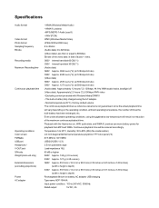
... (9000 x 6000 max.) 8 to 48 kHz (Audio data) 4 to 320 kbps (Video data) Less than MP3 and WMA. Continuous playback time will result in battery fully charged using the gigabeat at 500 kbps bit rate) (Audio data) Approximately 12 hours (*2): 128kbps, 44.1Hz WMA audio tracks, backlight off (Video data... number of the video data is not guaranteed, since the actual playback time will vary depending on , WAV audio data, and WMA 9 Lossless use more battery power for playback than or equal to 240 VAC, 50/60Hz Rated output: 5V DC, 3A Temperature: 5 to 35°C, Humidity: 30 to 80%...
... (9000 x 6000 max.) 8 to 48 kHz (Audio data) 4 to 320 kbps (Video data) Less than MP3 and WMA. Continuous playback time will result in battery fully charged using the gigabeat at 500 kbps bit rate) (Audio data) Approximately 12 hours (*2): 128kbps, 44.1Hz WMA audio tracks, backlight off (Video data... number of the video data is not guaranteed, since the actual playback time will vary depending on , WAV audio data, and WMA 9 Lossless use more battery power for playback than or equal to 240 VAC, 50/60Hz Rated output: 5V DC, 3A Temperature: 5 to 35°C, Humidity: 30 to 80%...