
User Guide
Page 11
.... Other documentation The server comes with the following documentation: The MAGNIA™ Z310 User's Guide (on the Documentation CD-ROM) contains instructions for Toshiba Servers contains safety information. Harness Eye/web runs on the documentation CDROM) contains Harness Eye/web settings and operation methods. xii Other icons used in the text. The Safety Instruction Guide for setting up and optimizing installation of Toshiba-authorized option drivers. Access Point User's Manual (for Windows / Linux) The Toshiba Server Setup Tool User's Guide (on the Documentation CD-ROM...
.... Other documentation The server comes with the following documentation: The MAGNIA™ Z310 User's Guide (on the Documentation CD-ROM) contains instructions for Toshiba Servers contains safety information. Harness Eye/web runs on the documentation CDROM) contains Harness Eye/web settings and operation methods. xii Other icons used in the text. The Safety Instruction Guide for setting up and optimizing installation of Toshiba-authorized option drivers. Access Point User's Manual (for Windows / Linux) The Toshiba Server Setup Tool User's Guide (on the Documentation CD-ROM...
User Guide
Page 14
... connector 22 (2) Security Loop 22 I/O connectors 23 Expansion slot 24 LAN status indicators 24 Inside the server 25 (1) Motherboard 25 (2) SCSI riser card 25 (3) Cooling fans 26 (4) CPU sockets 26 (5) Memory slots 26 (6) Expansion slot 26 (7) IDE HDD cage 26 (8) Board for wireless card 26 Connecting peripheral devices 26 How to connect peripheral devices 26 Connecting the power cable 30 Switching on the server 32 Turning on the server 32 Turning on the server by the "Remote Management" function...... 33 POST (Power On Self-Test 33 Starting...
... connector 22 (2) Security Loop 22 I/O connectors 23 Expansion slot 24 LAN status indicators 24 Inside the server 25 (1) Motherboard 25 (2) SCSI riser card 25 (3) Cooling fans 26 (4) CPU sockets 26 (5) Memory slots 26 (6) Expansion slot 26 (7) IDE HDD cage 26 (8) Board for wireless card 26 Connecting peripheral devices 26 How to connect peripheral devices 26 Connecting the power cable 30 Switching on the server 32 Turning on the server 32 Turning on the server by the "Remote Management" function...... 33 POST (Power On Self-Test 33 Starting...
User Guide
Page 17
... Starting the SCSI Utility 151 Menu configuration 152 SCSI Utility Keyboard Commands 152 Changing SCSI Device Settings 153 Setting Devices 153 Configuring MegaRAID IDE 156 Configuring MegaRAID IDE 156 Using the MegaRAID IDE Setup Utility 160 Auto Configure Stripe (F1 162 Auto Configure Mirror (F2 162 Create Array (F4 162 Delete Array (F5 166 Restore Old Configuration (F6 166 Edit Options (F7 166 Save and Exit (F10 167 Chapter 5: Installing Software 170 Windows NT® Server 4.0 170 Setting the motherboard...
... Starting the SCSI Utility 151 Menu configuration 152 SCSI Utility Keyboard Commands 152 Changing SCSI Device Settings 153 Setting Devices 153 Configuring MegaRAID IDE 156 Configuring MegaRAID IDE 156 Using the MegaRAID IDE Setup Utility 160 Auto Configure Stripe (F1 162 Auto Configure Mirror (F2 162 Create Array (F4 162 Delete Array (F5 166 Restore Old Configuration (F6 166 Edit Options (F7 166 Save and Exit (F10 167 Chapter 5: Installing Software 170 Windows NT® Server 4.0 170 Setting the motherboard...
User Guide
Page 19
interface 212 Expansion slots (64bit/66MHz PCI slot 213 Appendix C: Switch Setting 218 Hardware setup information 218 Appendix D: Trouble Information 222 Appendix E: Unit Logs 228 Unit logs 228 Basic system configuration 229 CPUs 229 Memories 229 IDE Hard disk drives 230 SCSI units 230 Expansion cards 230 Expansion units 231 Other optional items 231 xxi Appendix B: Interfaces 208 RGB interface 208 RGB interface synchronizing signals 209 Serial interface 210 Keyboard/mouse interface 211 LAN-1/2 interface 212 USB-
interface 212 Expansion slots (64bit/66MHz PCI slot 213 Appendix C: Switch Setting 218 Hardware setup information 218 Appendix D: Trouble Information 222 Appendix E: Unit Logs 228 Unit logs 228 Basic system configuration 229 CPUs 229 Memories 229 IDE Hard disk drives 230 SCSI units 230 Expansion cards 230 Expansion units 231 Other optional items 231 xxi Appendix B: Interfaces 208 RGB interface 208 RGB interface synchronizing signals 209 Serial interface 210 Keyboard/mouse interface 211 LAN-1/2 interface 212 USB-
User Guide
Page 34
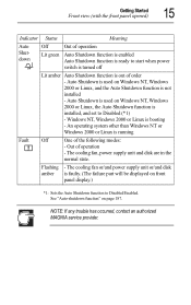
... Windows NT, Windows 2000 or Linux, the Auto Shutdown function is booting - NOTE: If any trouble has occurred, contact an authorized MAGNIA service provider. Flashing - Getting Started Front view (with the front panel opened) 15 Indicator Status Meaning Auto Shutdown Off Out of operation Lit green Auto Shutdown function is enabled Auto Shutdown function is ready to start when power switch is turned off Lit amber Auto Shutdown function is running Fault...
... Windows NT, Windows 2000 or Linux, the Auto Shutdown function is booting - NOTE: If any trouble has occurred, contact an authorized MAGNIA service provider. Flashing - Getting Started Front view (with the front panel opened) 15 Indicator Status Meaning Auto Shutdown Off Out of operation Lit green Auto Shutdown function is enabled Auto Shutdown function is ready to start when power switch is turned off Lit amber Auto Shutdown function is running Fault...
User Guide
Page 45
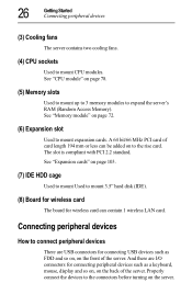
... 103. (7) IDE HDD cage Used to mount Used to the rise card. 26 Getting Started Connecting peripheral devices (3) Cooling fans The server contains two cooling fans. (4) CPU sockets Used to mount expansion cards. And there are USB connectors for wireless card can be added on to mount 3.5" hard disk (IDE). (8) Board for wireless card The board for connecting USB devices such as a keyboard, mouse, display and so on, on page 72. (6) Expansion slot Used to mount CPU modules. See "Memory module" on the back of the...
... 103. (7) IDE HDD cage Used to mount Used to the rise card. 26 Getting Started Connecting peripheral devices (3) Cooling fans The server contains two cooling fans. (4) CPU sockets Used to mount expansion cards. And there are USB connectors for wireless card can be added on to mount 3.5" hard disk (IDE). (8) Board for wireless card The board for connecting USB devices such as a keyboard, mouse, display and so on, on page 72. (6) Expansion slot Used to mount CPU modules. See "Memory module" on the back of the...
User Guide
Page 52
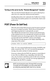
... kind of the error: one is by buzzer sound (beep code) in mid-course of the memory being accessed and tested by the POST is complete. Installing HarnessEye/web contained in connection with the network interface. During the memory test, the storage capacity of testing, and the other is by an error code and error message appearing on the display after the POST is shown on the display. If the key is automatically...
... kind of the error: one is by buzzer sound (beep code) in mid-course of the memory being accessed and tested by the POST is complete. Installing HarnessEye/web contained in connection with the network interface. During the memory test, the storage capacity of testing, and the other is by an error code and error message appearing on the display after the POST is shown on the display. If the key is automatically...
User Guide
Page 57
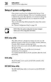
... set , store, etc.) the hardware resources of the configuration information. IDE RAID Setup utility The IDE RAID Setup utility is to be used to manage (set by the BIOS setup utility or the OS you are the following utilities prepared for the operation, adjust the clock periodically. NOTE: When the system configuration has been changed, make a note of the server, for use, it is desired to change the operating condition properly for example: memory addresses, I/O ports...
... set , store, etc.) the hardware resources of the configuration information. IDE RAID Setup utility The IDE RAID Setup utility is to be used to manage (set by the BIOS setup utility or the OS you are the following utilities prepared for the operation, adjust the clock periodically. NOTE: When the system configuration has been changed, make a note of the server, for use, it is desired to change the operating condition properly for example: memory addresses, I/O ports...
User Guide
Page 67
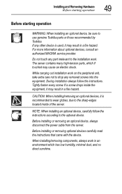
... part irrelevant to the sharp-edges located inside the equipment, it is used, it may result in an environment which if touched may result in a fire hazard. Before installing or removing optional devices carefully read the instructions that came with the device. For more information about optional devices, consult an authorized MAGNIA service provider. If a screw drops inside of the server. CAUTION: When installing/removing...
... part irrelevant to the sharp-edges located inside the equipment, it is used, it may result in an environment which if touched may result in a fire hazard. Before installing or removing optional devices carefully read the instructions that came with the device. For more information about optional devices, consult an authorized MAGNIA service provider. If a screw drops inside of the server. CAUTION: When installing/removing...
User Guide
Page 118
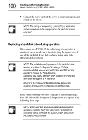
... setting of each drive before replacing a hard disk drive while the system is not replaced during operation If the server uses IDE RAID for replacement. Replacing a hard disk drive during system operation, confirm a faulty disk using the STS indicator of an operating system (OS) or application software may damage the server or destroy and lose important programs or data. Toshiba recommends that configure a disk array fails. (Downgraded operation) NOTE: The installation and replacement of the hard disk drives that you ask your authorized MAGNIA service provider...
... setting of each drive before replacing a hard disk drive while the system is not replaced during operation If the server uses IDE RAID for replacement. Replacing a hard disk drive during system operation, confirm a faulty disk using the STS indicator of an operating system (OS) or application software may damage the server or destroy and lose important programs or data. Toshiba recommends that configure a disk array fails. (Downgraded operation) NOTE: The installation and replacement of the hard disk drives that you ask your authorized MAGNIA service provider...
User Guide
Page 133
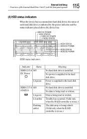
... Status HDD1/2/3/4 Off DC Power Lit green HDD1/2/3/4 Off STATUS Lit green Lit amber Flashing amber Meaning No hard disk drive is supplied to the hard disk drive. No hard disk drive is indicated by the power indicator and the status indicator placed above the device bay. External Unit Setup Front view of the External Hard Drive Unit Z1 (with the front panel opened) 115 (4) HDD status indicators When the device bay accommodates hard disk drives, the status of each hard disk drive is installed...
... Status HDD1/2/3/4 Off DC Power Lit green HDD1/2/3/4 Off STATUS Lit green Lit amber Flashing amber Meaning No hard disk drive is supplied to the hard disk drive. No hard disk drive is indicated by the power indicator and the status indicator placed above the device bay. External Unit Setup Front view of the External Hard Drive Unit Z1 (with the front panel opened) 115 (4) HDD status indicators When the device bay accommodates hard disk drives, the status of each hard disk drive is installed...
User Guide
Page 139
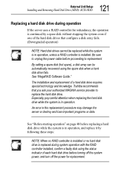
... service provider to replacement. The installation and replacement of each hard disk drive before proceeding to replace the hard disk drive. By setting a spare disk (hot spare), a disk array can be replaced while the system is replaced during operation If the server uses a RAID controller for replacement. 121 External Unit Setup Installing and Removing Hard Disk Drive (HDD) -SCSI HDD- Replacing a hard disk drive during system operation with the RAID controller installed, confirm a faulty disk using the spare disk when a hard disk drive fails. Toshiba recommends that configure...
... service provider to replacement. The installation and replacement of each hard disk drive before proceeding to replace the hard disk drive. By setting a spare disk (hot spare), a disk array can be replaced while the system is replaced during operation If the server uses a RAID controller for replacement. 121 External Unit Setup Installing and Removing Hard Disk Drive (HDD) -SCSI HDD- Replacing a hard disk drive during system operation with the RAID controller installed, confirm a faulty disk using the spare disk when a hard disk drive fails. Toshiba recommends that configure...
User Guide
Page 142
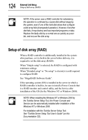
... the Toshiba Server Setup Tool: See "Toshiba Server Setup Tool User's Guide" (on this Documentation CD). See "MegaRAID Software Guide". If the operating system (OS) is installed in the server in which a RAID controller is built in the server before delivery, it is built in , be automatically installed after installation of the OS (for redundancy, the operation is continued by a normal one of the hard disk drives that is still required to install a Power Console that configure a disk array fails (downgraded operation...
... the Toshiba Server Setup Tool: See "Toshiba Server Setup Tool User's Guide" (on this Documentation CD). See "MegaRAID Software Guide". If the operating system (OS) is installed in the server in which a RAID controller is built in the server before delivery, it is built in , be automatically installed after installation of the OS (for redundancy, the operation is continued by a normal one of the hard disk drives that is still required to install a Power Console that configure a disk array fails (downgraded operation...
User Guide
Page 163
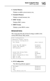
... Version Displays BMC version. BIOS Version Displays system BIOS version. Extended Memory Displays extended memory size. Advanced menu This section describes the advanced settings available in the various BIOS Setup Utility menus. PCI Configuration Advanced Chipset Control I/O Device Configuration PS/2 Mouse [Auto Detect] Local Bus IDE adapter Legacy USB Support USB Keyboard [Primary] [Enabled] [Disabled] Large Disk Access Mode: Installed O/S Reset Configuration Data Wake On LAN Wake On Ring PCI Configuration The following submenu appears: IDE RAID: SCSI: LAN: > PCI Device slot...
... Version Displays BMC version. BIOS Version Displays system BIOS version. Extended Memory Displays extended memory size. Advanced menu This section describes the advanced settings available in the various BIOS Setup Utility menus. PCI Configuration Advanced Chipset Control I/O Device Configuration PS/2 Mouse [Auto Detect] Local Bus IDE adapter Legacy USB Support USB Keyboard [Primary] [Enabled] [Disabled] Large Disk Access Mode: Installed O/S Reset Configuration Data Wake On LAN Wake On Ring PCI Configuration The following submenu appears: IDE RAID: SCSI: LAN: > PCI Device slot...
User Guide
Page 165
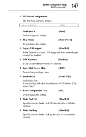
...setting. Large Disk Access Mode :[DOS] Do not change this setting. Reset Configuration Data :[No] Do not change this setting. Legacy USB support :[Enabled] When Disabled is set "Enabled". Wake On LAN :[Disabled] Specifies whether Wake On LAN function to be enabled or disabled. If you use the USB keyboard, set , the USB floppy disk drive can no longer be used. 147 System Configuration Setup BIOS setup utility I/O Device Configuration The following submenu appears. PS/2 Mouse :[Auto Detect] Do not change settings values. Installed O/S :[WinNT2K] Set installed...
...setting. Large Disk Access Mode :[DOS] Do not change this setting. Reset Configuration Data :[No] Do not change this setting. Legacy USB support :[Enabled] When Disabled is set "Enabled". Wake On LAN :[Disabled] Specifies whether Wake On LAN function to be enabled or disabled. If you use the USB keyboard, set , the USB floppy disk drive can no longer be used. 147 System Configuration Setup BIOS setup utility I/O Device Configuration The following submenu appears. PS/2 Mouse :[Auto Detect] Do not change settings values. Installed O/S :[WinNT2K] Set installed...
User Guide
Page 188
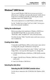
...for Windows 2000. Creating driver disks To manually install Windows 2000, you first need to copy a driver to a floppy disk, using the Toshiba Server Setup Tool or installing it automatically using the Toshiba Server Setup Tool. 171 Installing Software Windows® 2000 Server Windows® 2000 Server You can install Windows 2000 Server on your server in the Advanced menu. Intel LAN Windows 2000 Driver Selecting the disk driver Selecting the IDE CD-ROM Controller driver Use the driver contained on your system to a floppy disk. Start the Toshiba Server Setup Tool, select "Utilities...
...for Windows 2000. Creating driver disks To manually install Windows 2000, you first need to copy a driver to a floppy disk, using the Toshiba Server Setup Tool or installing it automatically using the Toshiba Server Setup Tool. 171 Installing Software Windows® 2000 Server Windows® 2000 Server You can install Windows 2000 Server on your server in the Advanced menu. Intel LAN Windows 2000 Driver Selecting the disk driver Selecting the IDE CD-ROM Controller driver Use the driver contained on your system to a floppy disk. Start the Toshiba Server Setup Tool, select "Utilities...
User Guide
Page 191
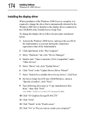
... Server, and log in the user ID of the Toshiba Server Setup Tool. To change the driver that of the Administrator. 2 Click right button in the "My Computer". 3 Select "Hardware" tab, click "Device Manager". 4 Double click "Video Controller (VGA Compatible)" under "Other devices". 5 Select "Driver" tab, click "Update Driver". 6 Click "Next" in the "Update Device Driver Wizard". 7 Select "Search for a suitable driver for my device", click Next 8 Set Server Setup Tool CD into CD-ROM drive, check at "Specify a location...
... Server, and log in the user ID of the Toshiba Server Setup Tool. To change the driver that of the Administrator. 2 Click right button in the "My Computer". 3 Select "Hardware" tab, click "Device Manager". 4 Double click "Video Controller (VGA Compatible)" under "Other devices". 5 Select "Driver" tab, click "Update Driver". 6 Click "Next" in the "Update Device Driver Wizard". 7 Select "Search for a suitable driver for my device", click Next 8 Set Server Setup Tool CD into CD-ROM drive, check at "Specify a location...
User Guide
Page 192
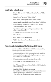
... SNMP Service in this order. 175 Installing Software Windows® 2000 Server Installing the network driver 1 Double click one of two "Ethernet Controller" under "Other devices" 2 Select "Driver" tab, click "Update Driver". 3 Click "Next" in the "Update Device Driver Wizard". 4 Select "Search for a suitable driver for my device", click Next 5 Set Server Setup Tool CD into CD-ROM drive, check at "Specify a location", click "Next". 6 Type following driver pass to "Copy manufacture's files from:", then click "Next" :\Public\Lan...
... SNMP Service in this order. 175 Installing Software Windows® 2000 Server Installing the network driver 1 Double click one of two "Ethernet Controller" under "Other devices" 2 Select "Driver" tab, click "Update Driver". 3 Click "Next" in the "Update Device Driver Wizard". 4 Select "Search for a suitable driver for my device", click Next 5 Set Server Setup Tool CD into CD-ROM drive, check at "Specify a location", click "Next". 6 Type following driver pass to "Copy manufacture's files from:", then click "Next" :\Public\Lan...
User Guide
Page 193
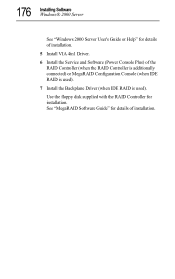
176 Installing Software Windows® 2000 Server See "Windows 2000 Server User's Guide or Help" for details of the RAID Controller (when the RAID Controller is additionally connected) or MegaRAID Configuration Console (when IDE RAID is used). 7 Install the Backplane Driver (when IDE RAID is used). See "MegaRAID Software Guide" for details of installation. 5 Install VIA 4in1 Driver. 6 Install the Service and Software (Power Console Plus) of installation. Use the floppy disk supplied with the RAID Controller for installation.
176 Installing Software Windows® 2000 Server See "Windows 2000 Server User's Guide or Help" for details of the RAID Controller (when the RAID Controller is additionally connected) or MegaRAID Configuration Console (when IDE RAID is used). 7 Install the Backplane Driver (when IDE RAID is used). See "MegaRAID Software Guide" for details of installation. 5 Install VIA 4in1 Driver. 6 Install the Service and Software (Power Console Plus) of installation. Use the floppy disk supplied with the RAID Controller for installation.
User Guide
Page 212
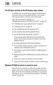
... hardware connection state up if added? 6 Is the correct version of each device driver installed? 7 Is the server selected if the switch box is used on a Rack Type? Check only the cables within the scope described in the floppy disk drive? 3 Are the jumper switches and other switches set properly on expansion cards and peripheral devices? 4 Are expansion cards and Hard Disk Drive (HDD) properly connected? 5 Is the Hard Disk Drive (HDD) properly formatted and set up to check the cause of the trouble...
... hardware connection state up if added? 6 Is the correct version of each device driver installed? 7 Is the server selected if the switch box is used on a Rack Type? Check only the cables within the scope described in the floppy disk drive? 3 Are the jumper switches and other switches set properly on expansion cards and peripheral devices? 4 Are expansion cards and Hard Disk Drive (HDD) properly connected? 5 Is the Hard Disk Drive (HDD) properly formatted and set up to check the cause of the trouble...