

User Manual
Page 6
... 2N • For clearance around the front bezel, it is recommended that only trained professionals install this DVD Rewriteable drive into your drive. If you prefer using DOS, download the ATAPI driver from our web site. 4 SETUP - SD-R6472 Toshiba recommends that a clearance of the four screws must be set • Mounting orientation: 15° (horizontally), 15...
... 2N • For clearance around the front bezel, it is recommended that only trained professionals install this DVD Rewriteable drive into your drive. If you prefer using DOS, download the ATAPI driver from our web site. 4 SETUP - SD-R6472 Toshiba recommends that a clearance of the four screws must be set • Mounting orientation: 15° (horizontally), 15...
User Manual
Page 9
... the Virus renders the DVD Rewriteable drive software drivers not useable. • Is the DVD Rewriteable drive software driver loaded? Avoid cleaning the disc using ? (i.e. Please contact Technical Support. • Is the DVD Rewriteable drive driver loaded • Is the DVD disc the correct format for the type of CD media (i.e. On a step-by the Operating System (i.e. SD-R6472 Problem Disc tray...
... the Virus renders the DVD Rewriteable drive software drivers not useable. • Is the DVD Rewriteable drive software driver loaded? Avoid cleaning the disc using ? (i.e. Please contact Technical Support. • Is the DVD Rewriteable drive driver loaded • Is the DVD disc the correct format for the type of CD media (i.e. On a step-by the Operating System (i.e. SD-R6472 Problem Disc tray...
Product Specification
Page 20
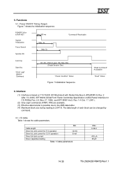
... Interface for 3.5 V operation 8 mA Driver IoH sink current Driver capacitive loading Table 1 Cable parameters Max 0.46 m -400 µA 25 pF 14 / 28 TS-L532A (SD-R6472) Rev.1.1 Min Cable length Driver IoL sink current for 5 V operation 12 mA Driver IoL sink current for CD-ROMs) Rev...(Mar. 13, 2003), SFF-8020i (Small Form Factor Committee Specification of each block can be changed by "TEST UNIT READY" Command CD: 20s, DVD 2 Layer: 18s, Max. 60s (Single Session Disc) "Check Condition" Status Figure 7 Initialization Sequence "Read Command" Acceptable "Good" Status 6. ...
... Interface for 3.5 V operation 8 mA Driver IoH sink current Driver capacitive loading Table 1 Cable parameters Max 0.46 m -400 µA 25 pF 14 / 28 TS-L532A (SD-R6472) Rev.1.1 Min Cable length Driver IoL sink current for 5 V operation 12 mA Driver IoL sink current for CD-ROMs) Rev...(Mar. 13, 2003), SFF-8020i (Small Form Factor Committee Specification of each block can be changed by "TEST UNIT READY" Command CD: 20s, DVD 2 Layer: 18s, Max. 60s (Single Session Disc) "Check Condition" Status Figure 7 Initialization Sequence "Read Command" Acceptable "Good" Status 6. ...

Product Specification
Page 21
...Rx Rs Type P N P N Timing Control Timing Control Receivers/Drivers Caracteristics without External pullup Resistor Min Max Condition VOH Voltage Output High ... Input Leakage Current Driver Sink Current Output Leakage Current Input Capacitance Output Capacitance Voltage Output High Voltage Output Low Driver Sink Current Output...Control VOH VOL IOL CO Voltage Output High Voltage Output Low Driver Sink Current Output Capacitance Vdd-0.4V 0.4V 24mA 15pF IOH=400..., PIN30, usually assigned to the "IOCS16" terminal in the past drives, is "NO CONNECTION" in Figure 12 and Figure 13, "Interface...
...Rx Rs Type P N P N Timing Control Timing Control Receivers/Drivers Caracteristics without External pullup Resistor Min Max Condition VOH Voltage Output High ... Input Leakage Current Driver Sink Current Output Leakage Current Input Capacitance Output Capacitance Voltage Output High Voltage Output Low Driver Sink Current Output...Control VOH VOL IOL CO Voltage Output High Voltage Output Low Driver Sink Current Output Capacitance Vdd-0.4V 0.4V 24mA 15pF IOH=400..., PIN30, usually assigned to the "IOCS16" terminal in the past drives, is "NO CONNECTION" in Figure 12 and Figure 13, "Interface...
Product Specification
Page 24
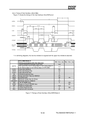
...) Cycle time allowing Data valid Setup time Data valid Hold time Unlimited Interlock time Setup and Hold Time for DMACKEnvelope time Minimum Delay time for Driver Minimum time for DMACKFirst STROBE time Ready-to-Final STROBE time Ready-to-Pause time Limited Interlock time Interlock with minimum Min time (ns) Max... interface Ultra DMA word. Timing of Host Interface (Ultra DMA) Figure 11 shows the timings of Host Interface (Ultra DMA Mode 2) 18 / 28 TS-L532A (SD-R6472) Rev.1.1
...) Cycle time allowing Data valid Setup time Data valid Hold time Unlimited Interlock time Setup and Hold Time for DMACKEnvelope time Minimum Delay time for Driver Minimum time for DMACKFirst STROBE time Ready-to-Final STROBE time Ready-to-Pause time Limited Interlock time Interlock with minimum Min time (ns) Max... interface Ultra DMA word. Timing of Host Interface (Ultra DMA) Figure 11 shows the timings of Host Interface (Ultra DMA Mode 2) 18 / 28 TS-L532A (SD-R6472) Rev.1.1


