Owners Manual
Page 14
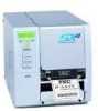
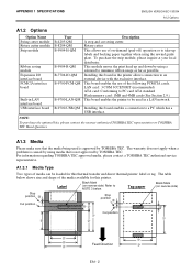
...To purchase the optional kits, please contact the nearest authorised TOSHIBA TEC representative or TOSHIBA TEC Head Quarters. PRODUCT OVERVIEW ENGLISH VERSION EO1-33058 1.6 Options 1.6 Options Option Name Type Description Swing cutter module B-4205-QM-R A stop and cut swing cutter. B-9704-RFID-U1-...enables read and write of the following PCMCIA cards. board USB interface board B-9700-USB-QM-R Installing this board in the printer allows connection to a PC which has a USB interface. Expansion I/O B-7704-IO-QM-R Installing this board enables a connection to an external ...
...To purchase the optional kits, please contact the nearest authorised TOSHIBA TEC representative or TOSHIBA TEC Head Quarters. PRODUCT OVERVIEW ENGLISH VERSION EO1-33058 1.6 Options 1.6 Options Option Name Type Description Swing cutter module B-4205-QM-R A stop and cut swing cutter. B-9704-RFID-U1-...enables read and write of the following PCMCIA cards. board USB interface board B-9700-USB-QM-R Installing this board in the printer allows connection to a PC which has a USB interface. Expansion I/O B-7704-IO-QM-R Installing this board enables a connection to an external ...
Owners Manual
Page 94
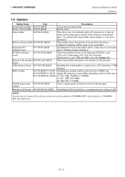
E6- 2 6. PRINTER SPECIFICATIONS ENGLISH VERSION EO1-33058 6. PRINTER SPECIFICATIONS Item Model B-SX4T-GS20-QM-R Available bar code types JAN8, JAN13, EAN8, EAN8+2 digits, EAN8+5 digits, EAN13, EAN13+2 digits, EAN13+5 digits, UPC...interface Serial interface (RS-232C) Parallel interface (Centronics) Optional interface PCMCIA interface (B-9700-PCM-QM-R) USB interface (B-9700-USB-QM-R) LAN interface (B-9700-LAN-QM-R) Expansion I/O interface (B-7704-IO-QM-R) Wireless LAN board (B-9700-WLAN-QM-R) NOTES: • Data MatrixTM is a trademark of International Data Matrix Inc., U.S. ...
E6- 2 6. PRINTER SPECIFICATIONS ENGLISH VERSION EO1-33058 6. PRINTER SPECIFICATIONS Item Model B-SX4T-GS20-QM-R Available bar code types JAN8, JAN13, EAN8, EAN8+2 digits, EAN8+5 digits, EAN13, EAN13+2 digits, EAN13+5 digits, UPC...interface Serial interface (RS-232C) Parallel interface (Centronics) Optional interface PCMCIA interface (B-9700-PCM-QM-R) USB interface (B-9700-USB-QM-R) LAN interface (B-9700-LAN-QM-R) Expansion I/O interface (B-7704-IO-QM-R) Wireless LAN board (B-9700-WLAN-QM-R) NOTES: • Data MatrixTM is a trademark of International Data Matrix Inc., U.S. ...

Owners Manual
Page 107
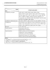
...) 3 TD (Transmit Data) 4 CTS (Clear to Send) 5 RTS (Request to Send) 6 DTR (Data Terminal Ready) 7 SG (Signal Ground) 20 DSR (Data Set Ready) USB interface (Option: B-9700-USB-QM-R) Physical Layer: Transfer type: Transfer rate: Class: Number of ports: Power source: Connector: Conforming to V1.1 Full speed Control transfer, Bulk transfer Full speed...
...) 3 TD (Transmit Data) 4 CTS (Clear to Send) 5 RTS (Request to Send) 6 DTR (Data Terminal Ready) 7 SG (Signal Ground) 20 DSR (Data Set Ready) USB interface (Option: B-9700-USB-QM-R) Physical Layer: Transfer type: Transfer rate: Class: Number of ports: Power source: Connector: Conforming to V1.1 Full speed Control transfer, Bulk transfer Full speed...
User Manual
Page 39
...SX4T-GS10-QP AC100 - 120V, 50/60 Hz±10% AC220 - 240V, 50 Hz±10% 1.6 A, 133 W maximum 1.0 A, 134 W maximum 0.18 A, 14 W maximum 0.13 A, 14 W maximum 5°C to 40°C (40°F to 104°F) 25% to 85% RH (no condensation) 8 dots/mm (203 dpi) Thermal transfer or Thermal direct...176;, 270° Serial interface (RS-232C) Parallel interface (Centronics) PCMCIA interface (B-9700-PCM-QM) USB interface (B-9700-USB-QM) LAN interface (B-9700-LAN-QM) Expansion I/O interface (B-7704-IO-QM) NOTES: • Data MatrixTM is a trademark of International Data Matrix Inc., U.S. •...
...SX4T-GS10-QP AC100 - 120V, 50/60 Hz±10% AC220 - 240V, 50 Hz±10% 1.6 A, 133 W maximum 1.0 A, 134 W maximum 0.18 A, 14 W maximum 0.13 A, 14 W maximum 5°C to 40°C (40°F to 104°F) 25% to 85% RH (no condensation) 8 dots/mm (203 dpi) Thermal transfer or Thermal direct...176;, 270° Serial interface (RS-232C) Parallel interface (Centronics) PCMCIA interface (B-9700-PCM-QM) USB interface (B-9700-USB-QM) LAN interface (B-9700-LAN-QM) Expansion I/O interface (B-7704-IO-QM) NOTES: • Data MatrixTM is a trademark of International Data Matrix Inc., U.S. •...
User Manual
Page 40
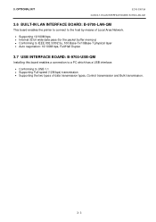
...apply when a problem is not approved by TOSHIBA TEC. Label Black Mark (on reverse side) Stop position Stop position Cut position Cut position Feed Direction EA1- 2 Installing this printer. Installing this thermal transfer and direct thermal printer: label or tag. LAN card: ...in LAN interface board USB interface board Type B-4205-QM B-8204-QM B-9904-H-QM B-9904-R-QM B-7704-IO-QM B-9700-PCM-QM B-9700-LAN-QM B-9700-USB-QM Description A stop and cut swing cutter. For information regarding TOSHIBA TEC approved media, please contact a TOSHIBA TEC authorised service representative. ...
...apply when a problem is not approved by TOSHIBA TEC. Label Black Mark (on reverse side) Stop position Stop position Cut position Cut position Feed Direction EA1- 2 Installing this printer. Installing this thermal transfer and direct thermal printer: label or tag. LAN card: ...in LAN interface board USB interface board Type B-4205-QM B-8204-QM B-9904-H-QM B-9904-R-QM B-7704-IO-QM B-9700-PCM-QM B-9700-LAN-QM B-9700-USB-QM Description A stop and cut swing cutter. For information regarding TOSHIBA TEC approved media, please contact a TOSHIBA TEC authorised service representative. ...

User Manual
Page 97
... 5°C to 40°C (40°F to 104°F) 25% to 85% RH (no condensation) 12 dots/mm (306 dpi) Thermal transfer or Thermal direct 76.2 mm/sec. (3 inches/sec.) 127.0 mm/sec (5 inches/sec.) For details, refer to Section A1.3.1. 203.2 mm/sec (8 inches...90°, 180°, 270° Serial interface (RS-232C) Parallel interface (Centronics) Expansion I/O interface PCMCIA interface (B-9700-PCM-QM) USB interface (B-9700-USB-QM) LAN interface (B-9700-LAN-QM) NOTES: • Data MatrixTM is a trademark of International Data Matrix Inc., U.S. • PDF417TM is a trademark of Symbol ...
... 5°C to 40°C (40°F to 104°F) 25% to 85% RH (no condensation) 12 dots/mm (306 dpi) Thermal transfer or Thermal direct 76.2 mm/sec. (3 inches/sec.) 127.0 mm/sec (5 inches/sec.) For details, refer to Section A1.3.1. 203.2 mm/sec (8 inches...90°, 180°, 270° Serial interface (RS-232C) Parallel interface (Centronics) Expansion I/O interface PCMCIA interface (B-9700-PCM-QM) USB interface (B-9700-USB-QM) LAN interface (B-9700-LAN-QM) NOTES: • Data MatrixTM is a trademark of International Data Matrix Inc., U.S. • PDF417TM is a trademark of Symbol ...

User Manual
Page 98
...-USB-QM Description A stop and cut swing cutter. A1.3.1 Media Type Two types of media can be used is not approved by TOSHIBA TEC. Tag paper Black Mark (on reverse side) Refer to NOTE 3 below shows size and shape of the following PCMCIA cards. Installing this board enables a connection to be loaded for this thermal...
...-USB-QM Description A stop and cut swing cutter. A1.3.1 Media Type Two types of media can be used is not approved by TOSHIBA TEC. Tag paper Black Mark (on reverse side) Refer to NOTE 3 below shows size and shape of the following PCMCIA cards. Installing this board enables a connection to be loaded for this thermal...
User Manual
Page 118
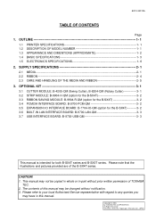
... LAN INTERFACE BOARD: B-9700-LAN-QM 3- 3 3.7 USB INTERFACE BOARD: B-9700-USB-QM 3- 3 This manual is intended for both B-SX4T series and B-SX5T series. The contents of this manual. CAUTION! 1. SUPPLY SPECIFICATIONS 2- 1 2.1 MEDIA 2- 1 2.2 RIBBON 2- 4 2.3 CARE AND HANDLING OF THE MEDIA AND RIBBON 2- 5 3. Please note that the illustrations and pictures provided are of TOSHIBA TEC. 2. OUTLINE 1- 1 1.1 PRINTER SPECIFICATIONS 1- 1 1.2 DESCRIPTION...
... LAN INTERFACE BOARD: B-9700-LAN-QM 3- 3 3.7 USB INTERFACE BOARD: B-9700-USB-QM 3- 3 This manual is intended for both B-SX4T series and B-SX5T series. The contents of this manual. CAUTION! 1. SUPPLY SPECIFICATIONS 2- 1 2.1 MEDIA 2- 1 2.2 RIBBON 2- 4 2.3 CARE AND HANDLING OF THE MEDIA AND RIBBON 2- 5 3. Please note that the illustrations and pictures provided are of TOSHIBA TEC. 2. OUTLINE 1- 1 1.1 PRINTER SPECIFICATIONS 1- 1 1.2 DESCRIPTION...
User Manual
Page 138
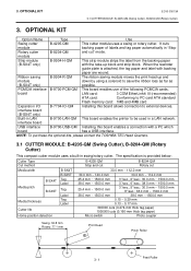
... 77.1 mm Print Head Pinch Roller Feed Roller 3- 1 NOTE: To purchase the optional kits, please contact the TOSHIBA TEC Head Quarters. 3.1 CUTTER MODULE: B-4205-QM (Swing Cutter), B-8204-QM (Rotary Cutter) This compact cutter module uses a built-in a LAN network. OPTIONAL KIT EO10-33013A 3.1 CUTTER ...automatically in LAN B-9700-LAN-QM This board enables the printer to save the ribbon loss as far as (B-SX4T only) possible. It cuts module backing paper of the following PCMCIA cards. interface board USB interface B-9700-USB-QM Installing this board allows connection ...
... 77.1 mm Print Head Pinch Roller Feed Roller 3- 1 NOTE: To purchase the optional kits, please contact the TOSHIBA TEC Head Quarters. 3.1 CUTTER MODULE: B-4205-QM (Swing Cutter), B-8204-QM (Rotary Cutter) This compact cutter module uses a built-in a LAN network. OPTIONAL KIT EO10-33013A 3.1 CUTTER ...automatically in LAN B-9700-LAN-QM This board enables the printer to save the ribbon loss as far as (B-SX4T only) possible. It cuts module backing paper of the following PCMCIA cards. interface board USB interface B-9700-USB-QM Installing this board allows connection ...
User Manual
Page 140
3. OPTIONAL KIT EO10-33013A 3.6 BUILT-IN LAN INTERFACE BOARD: B-9700-LAN-QM 3.6 BUILT-IN LAN INTERFACE BOARD: B-9700-LAN-QM This board enables the printer to connect to the host by means of Local Area Network. • Supporting 10/100M bps •..., 100 Base-Tx/10Base-T physical layer • Auto negotiation: 10/100M bps, Full/Half Duplex 3.7 USB INTERFACE BOARD: B-9700-USB-QM Installing this board enables a connection to a PC which has a USB interface. • Conforming to USB 1.1 • Supporting Full-speed (12M bps) transmission • Supporting the two types of data transmission ...
3. OPTIONAL KIT EO10-33013A 3.6 BUILT-IN LAN INTERFACE BOARD: B-9700-LAN-QM 3.6 BUILT-IN LAN INTERFACE BOARD: B-9700-LAN-QM This board enables the printer to connect to the host by means of Local Area Network. • Supporting 10/100M bps •..., 100 Base-Tx/10Base-T physical layer • Auto negotiation: 10/100M bps, Full/Half Duplex 3.7 USB INTERFACE BOARD: B-9700-USB-QM Installing this board enables a connection to a PC which has a USB interface. • Conforming to USB 1.1 • Supporting Full-speed (12M bps) transmission • Supporting the two types of data transmission ...
User Manual
Page 145
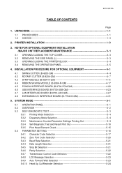
... INSTALLATION PROCEDURE FOR OPTIONAL EQUIPMENT 4- 1 4.1 SWING CUTTER (B-4205-QM 4- 4 4.2 ROTARY CUTTER (B-8204-QM 4- 7 4.3 STRIP MODULE (B-9904-H-QM 4-11 4.4 RIBBON SAVING MODULE (B-9904-R-QM 4-17 4.5 PCMCIA INTERFACE BOARD (B-9700-PCM-QM 4-20 4.6 USB INTERFACE BOARD (B-9700-USB-QM 4-23 4.7 LAN INTERFACE BOARD (B-9700-LAN-QM 4-27 4.8 EXPANSION I/O INTERFACE BOARD (B-7704-IO-QM 4-31 5. NOTE FOR OPTIONAL EQUIPMENT INSTALLATION /MAJOR UNIT REPLACEMENT...
... INSTALLATION PROCEDURE FOR OPTIONAL EQUIPMENT 4- 1 4.1 SWING CUTTER (B-4205-QM 4- 4 4.2 ROTARY CUTTER (B-8204-QM 4- 7 4.3 STRIP MODULE (B-9904-H-QM 4-11 4.4 RIBBON SAVING MODULE (B-9904-R-QM 4-17 4.5 PCMCIA INTERFACE BOARD (B-9700-PCM-QM 4-20 4.6 USB INTERFACE BOARD (B-9700-USB-QM 4-23 4.7 LAN INTERFACE BOARD (B-9700-LAN-QM 4-27 4.8 EXPANSION I/O INTERFACE BOARD (B-7704-IO-QM 4-31 5. NOTE FOR OPTIONAL EQUIPMENT INSTALLATION /MAJOR UNIT REPLACEMENT...
User Manual
Page 158
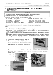
...following optional equipments are provided for these optional equipments are standard on the B-SX5T series, it is used together. 2. The B-9700-LAN-QM and the B-9700-USB-QM cannot be used in the built-in the batch or strip mode: Remove the two black screws to pinch your fingers or hands with... the B-9700-LAN-QM or the B-9700-USB-QM, attach the B-9700-PCM-QM onto the Main PC board. 4. When installing the B-4205-QM swing cutter module or B-8204-QM rotary cutter module on the B-SX5T series. 5. Make sure to remove the ...
...following optional equipments are provided for these optional equipments are standard on the B-SX5T series, it is used together. 2. The B-9700-LAN-QM and the B-9700-USB-QM cannot be used in the built-in the batch or strip mode: Remove the two black screws to pinch your fingers or hands with... the B-9700-LAN-QM or the B-9700-USB-QM, attach the B-9700-PCM-QM onto the Main PC board. 4. When installing the B-4205-QM swing cutter module or B-8204-QM rotary cutter module on the B-SX5T series. 5. Make sure to remove the ...
User Manual
Page 177
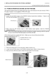
When using the LAN interface board or USB interface board together, install the PCMCIA interface board first. Rear Plate SM-3x6 Screw Blind Plate A 4-20 Loosen the two M-3x5 screws of the PCMCIA ... printer. (Refer to detach the blind plate A from the back. INSTALLATION PROCEDURE FOR OPTIONAL EQUIPMENT EO18-33012A 4.5 PCMCIA INTERFACE BOARD (B-9700-PCM-QM) 4.5 PCMCIA INTERFACE BOARD (B-9700-PCM-QM) This optional interface board is not applied to the connector. CAUTION! 1. Make sure you have all items shown below. All the following parts...
When using the LAN interface board or USB interface board together, install the PCMCIA interface board first. Rear Plate SM-3x6 Screw Blind Plate A 4-20 Loosen the two M-3x5 screws of the PCMCIA ... printer. (Refer to detach the blind plate A from the back. INSTALLATION PROCEDURE FOR OPTIONAL EQUIPMENT EO18-33012A 4.5 PCMCIA INTERFACE BOARD (B-9700-PCM-QM) 4.5 PCMCIA INTERFACE BOARD (B-9700-PCM-QM) This optional interface board is not applied to the connector. CAUTION! 1. Make sure you have all items shown below. All the following parts...
User Manual
Page 179
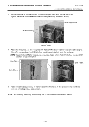
INSTALLATION PROCEDURE FOR OPTIONAL EQUIPMENT EO18-33012A 4.5 PCMCIA INTERFACE BOARD (B-9700-PCM-QM) 6) Secure the PCMCIA interface board to the Owner's Manual. 4-22 Tighten...Screw SM-3x6 screw 7) Attach the blind plate A to the next step. If the LAN interface board or USB interface board is installed. NOTE: For inserting, removing, and handling the PC card, refer to the PCB ...step 6). NOTE: Keep the two SM-3x6 screws and blind plate A safe when the LAN interface board or USB interface board is also installed, go to the rear plate with the SM-3x6 screw. If the Expansion I/O...
INSTALLATION PROCEDURE FOR OPTIONAL EQUIPMENT EO18-33012A 4.5 PCMCIA INTERFACE BOARD (B-9700-PCM-QM) 6) Secure the PCMCIA interface board to the Owner's Manual. 4-22 Tighten...Screw SM-3x6 screw 7) Attach the blind plate A to the next step. If the LAN interface board or USB interface board is installed. NOTE: For inserting, removing, and handling the PC card, refer to the PCB ...step 6). NOTE: Keep the two SM-3x6 screws and blind plate A safe when the LAN interface board or USB interface board is also installed, go to the rear plate with the SM-3x6 screw. If the Expansion I/O...
User Manual
Page 180
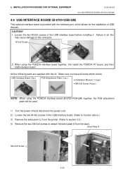
... using the PCMCIA interface board together, first install the PCMCIA PC board, and then USB interface board. CAUTION! 1. Loosen the two M-3x5 screws of USB devices. INSTALLATION PROCEDURE FOR OPTIONAL EQUIPMENT EO18-33012A 4.6 USB INTERFACE BOARD (B-9700-USB-QM) 4.6 USB INTERFACE BOARD (B-9700-USB-QM) This optional interface board is provided with the kit. M-3x5 Screw 2. When using...
... using the PCMCIA interface board together, first install the PCMCIA PC board, and then USB interface board. CAUTION! 1. Loosen the two M-3x5 screws of USB devices. INSTALLATION PROCEDURE FOR OPTIONAL EQUIPMENT EO18-33012A 4.6 USB INTERFACE BOARD (B-9700-USB-QM) 4.6 USB INTERFACE BOARD (B-9700-USB-QM) This optional interface board is provided with the kit. M-3x5 Screw 2. When using...
User Manual
Page 181
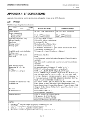
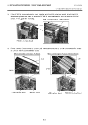
... connecting to CN7 on the Main PC board or CN1 on the USB interface board directly to the Main PC Board: When connecting the PCMCIA Interface Board: CN7 CN1 CN50 CN50 USB Interface Board Main PC Board USB Interface Board PCMCIA Interface Board 4-24 If not, go to which the... PCMCIA interface board is used together with the USB interface board, attach the PCB attachment plate to the plate to the next step. INSTALLATION PROCEDURE FOR OPTIONAL EQUIPMENT EO18-33012A 4.6 USB INTERFACE BOARD (B-9700-USB-QM) 5) If the PCMCIA interface board is secured with the SM-...
... connecting to CN7 on the Main PC board or CN1 on the USB interface board directly to the Main PC Board: When connecting the PCMCIA Interface Board: CN7 CN1 CN50 CN50 USB Interface Board Main PC Board USB Interface Board PCMCIA Interface Board 4-24 If not, go to which the... PCMCIA interface board is used together with the USB interface board, attach the PCB attachment plate to the plate to the next step. INSTALLATION PROCEDURE FOR OPTIONAL EQUIPMENT EO18-33012A 4.6 USB INTERFACE BOARD (B-9700-USB-QM) 5) If the PCMCIA interface board is secured with the SM-...
User Manual
Page 182
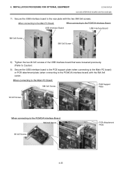
INSTALLATION PROCEDURE FOR OPTIONAL EQUIPMENT EO18-33012A 4.6 USB INTERFACE BOARD (B-9700-USB-QM) 7) Secure the USB interface board to the PCMCIA Interface Board: SM-3x6 Screw M-3x5 Screw PCB Attachment Plate 4-25 When connecting to the Main PC Board: SM-3x6 ... the Main PC Board: When connecting to the PCMCIA Interface Board: USB Interface Board USB Interface Board SM-3x6 Screw SM-3x6 Screw 8) Tighten the two M-3x5 screws of the USB interface board that were loosened previously. (Refer to Caution) 9) Secure the USB interface board to the PCB support plate (when connecting to the...
INSTALLATION PROCEDURE FOR OPTIONAL EQUIPMENT EO18-33012A 4.6 USB INTERFACE BOARD (B-9700-USB-QM) 7) Secure the USB interface board to the PCMCIA Interface Board: SM-3x6 Screw M-3x5 Screw PCB Attachment Plate 4-25 When connecting to the Main PC Board: SM-3x6 ... the Main PC Board: When connecting to the PCMCIA Interface Board: USB Interface Board USB Interface Board SM-3x6 Screw SM-3x6 Screw 8) Tighten the two M-3x5 screws of the USB interface board that were loosened previously. (Refer to Caution) 9) Secure the USB interface board to the PCB support plate (when connecting to the...
User Manual
Page 183
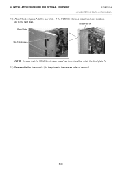
If the PCMCIA interface board has been installed, go to the printer in the reverse order of removal. 4-26 4. Blind Plate A Rear Plate SM-3x6 Screw NOTE: In case that the PCMCIA interface board has been installed, retain the blind plate A. 11) Reassemble the side panel (L) to the next step. INSTALLATION PROCEDURE FOR OPTIONAL EQUIPMENT EO18-33012A 4.6 USB INTERFACE BOARD (B-9700-USB-QM) 10) Attach the blind plate A to the rear plate.
If the PCMCIA interface board has been installed, go to the printer in the reverse order of removal. 4-26 4. Blind Plate A Rear Plate SM-3x6 Screw NOTE: In case that the PCMCIA interface board has been installed, retain the blind plate A. 11) Reassemble the side panel (L) to the next step. INSTALLATION PROCEDURE FOR OPTIONAL EQUIPMENT EO18-33012A 4.6 USB INTERFACE BOARD (B-9700-USB-QM) 10) Attach the blind plate A to the rear plate.
