

Owners Manual
Page 8
...-in AC Power Cord 8 4.5 Setting Up Keyboard and Display 10 4.5.1 Use of Plasma Display and External Keyboard 10 4.5.2 Use of CRT and External Keyboard 11 4.5.3 Use of Plasma Display and Internal Keyboard 11 4.6 A-B-PRT Switch Setting 12 4.6.1 No Printer, No External Drive 12 4.6.2 Printer, No External Drive 12 4.6.3 External Drive, No Printer 13 4.6.4 Both a Printer and an External Drive 13 4.7 Setting DIP Switch 14 4.8 Colour CRT Display Connection 16 4.9 Printer Connection 17 4.10 External Floppy Disk Drive Connection 18 PART 5 DISKS AND DISK DRIVE 5.1 Concepts...
...-in AC Power Cord 8 4.5 Setting Up Keyboard and Display 10 4.5.1 Use of Plasma Display and External Keyboard 10 4.5.2 Use of CRT and External Keyboard 11 4.5.3 Use of Plasma Display and Internal Keyboard 11 4.6 A-B-PRT Switch Setting 12 4.6.1 No Printer, No External Drive 12 4.6.2 Printer, No External Drive 12 4.6.3 External Drive, No Printer 13 4.6.4 Both a Printer and an External Drive 13 4.7 Setting DIP Switch 14 4.8 Colour CRT Display Connection 16 4.9 Printer Connection 17 4.10 External Floppy Disk Drive Connection 18 PART 5 DISKS AND DISK DRIVE 5.1 Concepts...

Owners Manual
Page 9
... 12 5.7.6 Disk Write Protection 12 5.7.7 Labeling Disks 13 5.7.8 Disk Insertion 13 5.7.9 Disk Removal 14 5.7.10 Connecting AC Adaptor 14 PART 6 OPERATION 6.1 Before You Begin 1 6.2 Turning Power ON 2 6.3 Power -on Self -test 3 6.4 Setup Execution 5 6.5 Loading MS-DOS 11 6.5.1 Loading MS-DOS from Floppy Disk Drive 11 6.5.2 Loading MS-DOS from Hard Disk Drive 13 6.6 Set Up Gray Scale 14 6.7 Keyboard 15 6.7.1 Soft Switches 17 6.8 System Initialisation 18 6.9 Disk Removal from Drive 19 6.10 Turning Power OFF...
... 12 5.7.6 Disk Write Protection 12 5.7.7 Labeling Disks 13 5.7.8 Disk Insertion 13 5.7.9 Disk Removal 14 5.7.10 Connecting AC Adaptor 14 PART 6 OPERATION 6.1 Before You Begin 1 6.2 Turning Power ON 2 6.3 Power -on Self -test 3 6.4 Setup Execution 5 6.5 Loading MS-DOS 11 6.5.1 Loading MS-DOS from Floppy Disk Drive 11 6.5.2 Loading MS-DOS from Hard Disk Drive 13 6.6 Set Up Gray Scale 14 6.7 Keyboard 15 6.7.1 Soft Switches 17 6.8 System Initialisation 18 6.9 Disk Removal from Drive 19 6.10 Turning Power OFF...

Owners Manual
Page 10
PART 7 USING MS-DOS 7.1 Starting MS-DOS 1 7.2 Entering Date and Time 3 7.2.1 Entering Date 3 7.2.2 Entering Time 5 7.3 Setting Up Gray Scale for Plasma Display 7 7.3.1 To Change Gray Scale 7 7.3.2 To Use XCHAD Menu 8 7.3.3 Command Mode 11 7.4 Changing Current Disk Drive 14 7.5 Using Keyboard 15 7.5.1 Data Keys 15 7.5.2 Correction of a Typing Mistake 17 7.5.3 Entering Command 17 7.5.4 Stopping Command Execution 18 7.5.5 Suspending Screen Output 18 7.5.6 Making Hard Copy of Screen Information 19 7.5.7 Restarting MS-DOS 19 7.6 Disk Files 20 7.6.1 Definition of...
PART 7 USING MS-DOS 7.1 Starting MS-DOS 1 7.2 Entering Date and Time 3 7.2.1 Entering Date 3 7.2.2 Entering Time 5 7.3 Setting Up Gray Scale for Plasma Display 7 7.3.1 To Change Gray Scale 7 7.3.2 To Use XCHAD Menu 8 7.3.3 Command Mode 11 7.4 Changing Current Disk Drive 14 7.5 Using Keyboard 15 7.5.1 Data Keys 15 7.5.2 Correction of a Typing Mistake 17 7.5.3 Entering Command 17 7.5.4 Stopping Command Execution 18 7.5.5 Suspending Screen Output 18 7.5.6 Making Hard Copy of Screen Information 19 7.5.7 Restarting MS-DOS 19 7.6 Disk Files 20 7.6.1 Definition of...

Owners Manual
Page 14
... some other internal and/or external option boards and devices. o A powerful 80286-12 microprocessor chip operates at a clock rate of random access memory (RAM) are standard, allowing you can connect an external 5.25-inch floppy disk drive through this port. 1-2 o 1 megabyte of 12 megahertz. For most popular software packages without buying more memory. Through it can connect any Centronics compatible printer. The system unit includes the following key components.
... some other internal and/or external option boards and devices. o A powerful 80286-12 microprocessor chip operates at a clock rate of random access memory (RAM) are standard, allowing you can connect an external 5.25-inch floppy disk drive through this port. 1-2 o 1 megabyte of 12 megahertz. For most popular software packages without buying more memory. Through it can connect any Centronics compatible printer. The system unit includes the following key components.

Owners Manual
Page 16
... key caps needs to be replaced in order to 4 megabytes. o Key Cap Set, is provided for each of USA, Germany, France, Spain, Scandinavia, Italy and Switzerland. o A 3 megabytes memory expansion card increases the T3200's RAM size to reflect the corresponding system kit used. This disk stores MS-DOS as the T3200 operating system, and diagnostics which effectively improves the T3200 reliability. o An ac powered external...
... key caps needs to be replaced in order to 4 megabytes. o Key Cap Set, is provided for each of USA, Germany, France, Spain, Scandinavia, Italy and Switzerland. o A 3 megabytes memory expansion card increases the T3200's RAM size to reflect the corresponding system kit used. This disk stores MS-DOS as the T3200 operating system, and diagnostics which effectively improves the T3200 reliability. o An ac powered external...

Owners Manual
Page 17
... compatible, allowing you choose the comfortable angle of useful indicator lights. o The T3200 is easy to run PC software. o The T3200 comes with this User's Manual and an MS-DOS Reference Manual. 1-5 o Hardware options are kept by a battery powered calendar clock. o The T3200 has a variety of operation. o The date and time are easily selected using the configuration switches, A-B-PRT switch and voltage switch. o The adjustable display panel lets you to...
... compatible, allowing you choose the comfortable angle of useful indicator lights. o The T3200 is easy to run PC software. o The T3200 comes with this User's Manual and an MS-DOS Reference Manual. 1-5 o Hardware options are kept by a battery powered calendar clock. o The T3200 has a variety of operation. o The date and time are easily selected using the configuration switches, A-B-PRT switch and voltage switch. o The adjustable display panel lets you to...

Owners Manual
Page 30
... SETTING-UP Setup procedure for each part of Plasma Display and Internal Keyboard 11 4.6 A-B-PRT Switch Setting 12 4.6.1 No Printer, No External Drive 12 4.6.2 Printer, No External Drive 12 4.6.3 External Drive, No Printer 13 4.6.4 Both a Printer and an External Drive 13 4.7 Setting DIP Switch 14 4.8 Colour CRT Display Connection 16 4.9 Printer Connection 17 4.10 External Floppy Disk Drive Connection 18 This part contains: 4.1 System Unit 1 4.2 System Unit Components 2 4.3 Switches and Connectors 4 4.4 Plugging-in AC Power Cord 8 4.5 Setting Up Keyboard and Display...
... SETTING-UP Setup procedure for each part of Plasma Display and Internal Keyboard 11 4.6 A-B-PRT Switch Setting 12 4.6.1 No Printer, No External Drive 12 4.6.2 Printer, No External Drive 12 4.6.3 External Drive, No Printer 13 4.6.4 Both a Printer and an External Drive 13 4.7 Setting DIP Switch 14 4.8 Colour CRT Display Connection 16 4.9 Printer Connection 17 4.10 External Floppy Disk Drive Connection 18 This part contains: 4.1 System Unit 1 4.2 System Unit Components 2 4.3 Switches and Connectors 4 4.4 Plugging-in AC Power Cord 8 4.5 Setting Up Keyboard and Display...

Owners Manual
Page 35
... IN Jack : Supplies ac power to select various configuration options. By this, the port can connect an I /O port. This connector can be used . (6) AC IN Change Switch : is 115 or 230 volts. Setting the A-B-PRT Switch to PRT and DIP Switch 2 to ON makes this switch is blanked off and access by a user is a 9-pin D-Shell female connector to connect an RGB direct drive colour CRT display. Normally this port general I /O device...
... IN Jack : Supplies ac power to select various configuration options. By this, the port can connect an I /O port. This connector can be used . (6) AC IN Change Switch : is 115 or 230 volts. Setting the A-B-PRT Switch to PRT and DIP Switch 2 to ON makes this switch is blanked off and access by a user is a 9-pin D-Shell female connector to connect an RGB direct drive colour CRT display. Normally this port general I /O device...

Owners Manual
Page 37
Adjust the angle of the screen first, then use the Plasma Display contrast/brightness dial to fine tune the display to .el ( ) 4-7 Figure 4-5 Left Side Panel to your satisfaction. Slot : is protected by a cover that can be removed to connect an external keyboard. (4) Plasma Contrast/Brightness Dial : Controls the contrast or brightness of the Plasma Display screen. PART 4 SETTING-UP (3) Keyboard Connector : Is used to allow installation of the expansion options. Left Side (1) EXP.
Adjust the angle of the screen first, then use the Plasma Display contrast/brightness dial to fine tune the display to .el ( ) 4-7 Figure 4-5 Left Side Panel to your satisfaction. Slot : is protected by a cover that can be removed to connect an external keyboard. (4) Plasma Contrast/Brightness Dial : Controls the contrast or brightness of the Plasma Display screen. PART 4 SETTING-UP (3) Keyboard Connector : Is used to allow installation of the expansion options. Left Side (1) EXP.
Owners Manual
Page 40
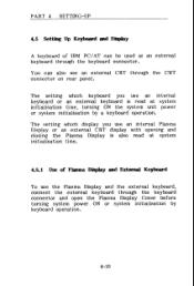
PART 4 SETTING-UP 4.5 Setting Up Keyboard and Display A keyboard of Plasma Display and External Keyboard To use the Plasma Display and the external keyboard, connect the external keyboard through the keyboard connector and open the Plasma Display Cover before turning system power ON or system initialisation by a keyboard operation. The setting which keyboard you use an external CRT through the keyboard connector. The setting which display you use an internal keyboard or an external keyboard is also read at system initialisation time. 4.5.1 Use of IBM PC/AT can...
PART 4 SETTING-UP 4.5 Setting Up Keyboard and Display A keyboard of Plasma Display and External Keyboard To use the Plasma Display and the external keyboard, connect the external keyboard through the keyboard connector and open the Plasma Display Cover before turning system power ON or system initialisation by a keyboard operation. The setting which keyboard you use an external CRT through the keyboard connector. The setting which display you use an internal keyboard or an external keyboard is also read at system initialisation time. 4.5.1 Use of IBM PC/AT can...
Owners Manual
Page 41
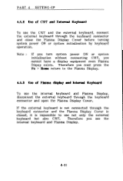
... initialisation without connecting CRT, you use the CRT and the external keyboard, connect the external keyboard through the keyboard connector and close the Plasma Display Cover before turning system power ON or system initialisation by keyboard operation. If the external keyboard is not connected through the keyboard connector and open the Plasma Display Cover. PART 4 SETTING -UP 4.5.2 Use of Plasma display and Internal Keyboard To use the internal keyboard and Plasma Display, disconnect the external keyboard through the keyboard connector and the Plasma Display Cover is...
... initialisation without connecting CRT, you use the CRT and the external keyboard, connect the external keyboard through the keyboard connector and close the Plasma Display Cover before turning system power ON or system initialisation by keyboard operation. If the external keyboard is not connected through the keyboard connector and open the Plasma Display Cover. PART 4 SETTING -UP 4.5.2 Use of Plasma display and Internal Keyboard To use the internal keyboard and Plasma Display, disconnect the external keyboard through the keyboard connector and the Plasma Display Cover is...
Owners Manual
Page 42
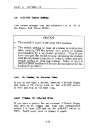
.... 4-12 PART 4 SETTING-UP 4.6 A-B-PRT Switch Setting This switch changes over the addresses (-A or -B) of the Floppy Disk Drives (FDDs). Refer to Part 6 OPERATION Section 6.8 System Initialisation for the keyboard operation. 4.6.1 No Printer, No External Drive If you have a printer but no external 5.25-inch floppy disk drive or PC Floppy Link, make sure configuration switch 2 is read at system initialisation time, turning ON the system unit power or system initialisation by a keyboard operation.
.... 4-12 PART 4 SETTING-UP 4.6 A-B-PRT Switch Setting This switch changes over the addresses (-A or -B) of the Floppy Disk Drives (FDDs). Refer to Part 6 OPERATION Section 6.8 System Initialisation for the keyboard operation. 4.6.1 No Printer, No External Drive If you have a printer but no external 5.25-inch floppy disk drive or PC Floppy Link, make sure configuration switch 2 is read at system initialisation time, turning ON the system unit power or system initialisation by a keyboard operation.
Owners Manual
Page 43
... connect the drive's cable to the FDD/PRT port. 4-13 PART 4 SETTING-UP 4.6.3 External Drive, No Printer If you have an external 5.25-inch floppy disk drive or the PC Floppy Link in your IBM compatible computer, the A--B-PRT switch should be set to either A or B depending on how you want the A-B-PRT switch set to B. This way the internal disk drive is -A, the external drive is -B and the fixed disk is drive...
... connect the drive's cable to the FDD/PRT port. 4-13 PART 4 SETTING-UP 4.6.3 External Drive, No Printer If you have an external 5.25-inch floppy disk drive or the PC Floppy Link in your IBM compatible computer, the A--B-PRT switch should be set to either A or B depending on how you want the A-B-PRT switch set to B. This way the internal disk drive is -A, the external drive is -B and the fixed disk is drive...

Owners Manual
Page 66
... keyboard, discusses backup procedures and serial configuration parameters, and concludes with simple maintenance you can do on your own. 6.1 Before You Begin 1 6.2 Turning Power ON 2 6.3 Power -on Self -test 3 6.4 Setup Execution 5 6.5 Loading MS-DOS 11 6.5.1 Loading MS-DOS from Floppy Disk Drive 11 6.5.2 Loading MS-DOS from Hard Disk Drive 13 6.6 Setting Up Gray Scale 14 6.7 Keyboard 15 6.7.1 Soft Switches 17 6.8 System Initialisation 18 6.9 Disk Removal from Drive 19 6.10 Turning Power...
... keyboard, discusses backup procedures and serial configuration parameters, and concludes with simple maintenance you can do on your own. 6.1 Before You Begin 1 6.2 Turning Power ON 2 6.3 Power -on Self -test 3 6.4 Setup Execution 5 6.5 Loading MS-DOS 11 6.5.1 Loading MS-DOS from Floppy Disk Drive 11 6.5.2 Loading MS-DOS from Hard Disk Drive 13 6.6 Setting Up Gray Scale 14 6.7 Keyboard 15 6.7.1 Soft Switches 17 6.8 System Initialisation 18 6.9 Disk Removal from Drive 19 6.10 Turning Power...
Owners Manual
Page 67
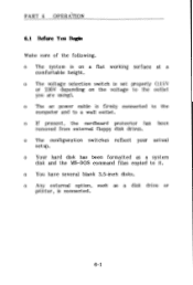
... removed from external floppy disk drives. o The configuration switches reflect your actual setup. o Any external option, such as a system disk and the MS-DOS command files copied to it. o The voltage selection switch is connected. 6-1 o The ac power cable is on the voltage to a wall outlet. o Your hard disk has been formatted as a disk drive or printer, is set properly (115V or 230V depending on a flat working surface at a comfortable height. PART 6 OPERATION...
... removed from external floppy disk drives. o The configuration switches reflect your actual setup. o Any external option, such as a system disk and the MS-DOS command files copied to it. o The voltage selection switch is connected. 6-1 o The ac power cable is on the voltage to a wall outlet. o Your hard disk has been formatted as a disk drive or printer, is set properly (115V or 230V depending on a flat working surface at a comfortable height. PART 6 OPERATION...
Owners Manual
Page 131
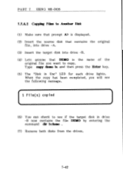
... command dir b:demo . (7) Remove both disks from the drives. 7-42 PART 7 USING MS-DOS 7.7.6.2 Copying Files to Another Disk (1) Make sure that prompt A> is displayed. (2) Insert the source disk that contains the original file, into drive -A. (3) Insert the target disk into drive -B. (4) Lets assume that DEMO is the name of the original file you will see if the target disk in Use" LED for each drive lights.
... command dir b:demo . (7) Remove both disks from the drives. 7-42 PART 7 USING MS-DOS 7.7.6.2 Copying Files to Another Disk (1) Make sure that prompt A> is displayed. (2) Insert the source disk that contains the original file, into drive -A. (3) Insert the target disk into drive -B. (4) Lets assume that DEMO is the name of the original file you will see if the target disk in Use" LED for each drive lights.
Owners Manual
Page 146
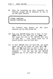
... be started directly from the fixed disk. (11) To boot MS-DOS from the hard disk, you enter the date and time, prompt C> is displayed. Your system could now be displayed, as well as you would simply turn ON the power (or reset with Ctrl , Alt , and Del keys) with a floppy disk. 7-57 You can now use with no disk in drive -A, type COPY *.* C: and then press the Enter key.
... be started directly from the fixed disk. (11) To boot MS-DOS from the hard disk, you enter the date and time, prompt C> is displayed. Your system could now be displayed, as well as you would simply turn ON the power (or reset with Ctrl , Alt , and Del keys) with a floppy disk. 7-57 You can now use with no disk in drive -A, type COPY *.* C: and then press the Enter key.

Owners Manual
Page 164
PART 8 TROUBLESHOOTING (9-1) Type 0 and press the Enter key for a T3200 with one floppy disk drive and one hard disk drive. 8-16 Cy1=614,h=8,s/t=17 3.Memory size System memory Extended memory Expanded memory = 640KB = 0MB = 384KB+ 0MB 4.External display card = None Select setup change (1:No/2:Yes) ? 1/ Note that the above setup description is an example for SETUP, the test displays the system setup description as follows. .1k [[ System setup ]] 1.Floppy disk drives = 1 Drive#1 type = 2 - 720KB/1.2MB Drive#2 type = 0 - No drive 2.Hard disk drives =1 Drive#1 type = 4 -
PART 8 TROUBLESHOOTING (9-1) Type 0 and press the Enter key for a T3200 with one floppy disk drive and one hard disk drive. 8-16 Cy1=614,h=8,s/t=17 3.Memory size System memory Extended memory Expanded memory = 640KB = 0MB = 384KB+ 0MB 4.External display card = None Select setup change (1:No/2:Yes) ? 1/ Note that the above setup description is an example for SETUP, the test displays the system setup description as follows. .1k [[ System setup ]] 1.Floppy disk drives = 1 Drive#1 type = 2 - 720KB/1.2MB Drive#2 type = 0 - No drive 2.Hard disk drives =1 Drive#1 type = 4 -
Owners Manual
Page 169
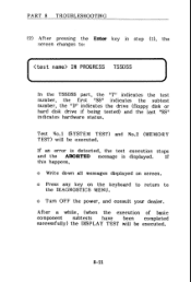
..." indicates the subtest number, the "D" indicates the drive (floppy disk or hard disk drive if being tested) and the last "SS" indicates hardware status. o Turn OFF the power, and consult your dealer. After a while, (when the execution of basic component subtests have been completed successfully) the DISPLAY TEST will be executed. 8-21 PART 8 TROUBLESHOOTING (2) After pressing the Enter key in step (1), the screen changes to the DIAGNOSTICS MENU. If an error...
..." indicates the subtest number, the "D" indicates the drive (floppy disk or hard disk drive if being tested) and the last "SS" indicates hardware status. o Turn OFF the power, and consult your dealer. After a while, (when the execution of basic component subtests have been completed successfully) the DISPLAY TEST will be executed. 8-21 PART 8 TROUBLESHOOTING (2) After pressing the Enter key in step (1), the screen changes to the DIAGNOSTICS MENU. If an error...

Owners Manual
Page 189
... the wall outlet ? o Is there ac power from the wall outlet ? o Is the printer signal cable properly connected to the printer's "Owners Manual" for instructions on the display screen. o Are the ribbon, forms, tractor, and printer control switches set properly ? (Refer to the printer and the system unit ? PART 8 TROUBLESHOOTING If a problem occurs, the message ABORTED appears on troubleshooting of the printer.) 8-41 Check the...
... the wall outlet ? o Is there ac power from the wall outlet ? o Is the printer signal cable properly connected to the printer's "Owners Manual" for instructions on the display screen. o Are the ribbon, forms, tractor, and printer control switches set properly ? (Refer to the printer and the system unit ? PART 8 TROUBLESHOOTING If a problem occurs, the message ABORTED appears on troubleshooting of the printer.) 8-41 Check the...


