
Owners Manual
Page 4
... SERVICING TO QUALIFIED SERVICE PERSONNEL ONLY. 2. Power Sources This product should not be blocked by the user. This product should be blocked or covered. Source of power supply to ensure reliable operation of power source indicated on . Read Owner's Manual After unpacking this unit will protect you if you are provided for installation, use IMPORTANT SAFETY INSTRUCTIONS CONTENTS 4 CAUTION: PLEASE READ AND OBSERVE ALL WARNINGS AND INSTRUCTIONS GIVEN IN THIS OWNER'S MANUAL...
... SERVICING TO QUALIFIED SERVICE PERSONNEL ONLY. 2. Power Sources This product should not be blocked by the user. This product should be blocked or covered. Source of power supply to ensure reliable operation of power source indicated on . Read Owner's Manual After unpacking this unit will protect you if you are provided for installation, use IMPORTANT SAFETY INSTRUCTIONS CONTENTS 4 CAUTION: PLEASE READ AND OBSERVE ALL WARNINGS AND INSTRUCTIONS GIVEN IN THIS OWNER'S MANUAL...

Owners Manual
Page 7
... safety checks to dangerous voltage or other hazards. (Replacement of the lamp only should be sure the service technician has used replacement parts specified by following conditions: a) When the power-supply cord or plug is in that the product is damaged. Unauthorized substitutions may result in fire, electric shock, or other hazards. Replacement Parts When replacement parts are covered by the operating instructions as an improper adjustment of...
... safety checks to dangerous voltage or other hazards. (Replacement of the lamp only should be sure the service technician has used replacement parts specified by following conditions: a) When the power-supply cord or plug is in that the product is damaged. Unauthorized substitutions may result in fire, electric shock, or other hazards. Replacement Parts When replacement parts are covered by the operating instructions as an improper adjustment of...

Owners Manual
Page 10
... menu setting 53 Document imaging camera Part names (of the document imaging camera model 54 Preparation of the document imaging camera 55 Picture projection with the document imaging camera 56 Overlaying projection 59 Lock the white balance 60 Correcting illuminated defects 61 Maintenance Trouble indications 62 Air filter cleaning 63 Lens and main unit cleaning 65 Lamp replacement 66 Others Before calling service personal 68 Pin assignment of each part on the screen 28 Turning the power...
... menu setting 53 Document imaging camera Part names (of the document imaging camera model 54 Preparation of the document imaging camera 55 Picture projection with the document imaging camera 56 Overlaying projection 59 Lock the white balance 60 Correcting illuminated defects 61 Maintenance Trouble indications 62 Air filter cleaning 63 Lens and main unit cleaning 65 Lamp replacement 66 Others Before calling service personal 68 Pin assignment of each part on the screen 28 Turning the power...
Owners Manual
Page 14
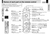
...) : 1mW PIP button To display the video input 40 image as 42 USB remote control mouse. MENU ENTER EXIT PIP FREEZE CALL RESIZE MUTE Selection button ENTER button EXIT button MENU button To display the menu screen and/or select the operation on or off the picture and sound temporarily. Laser emission part Remote control transmission part INPUT ON/STANDBY LASER KEYSTONE AUTO SET ON/STANDBY button 28 33 To turn the projector on the menu screen. 43 44 Use the selection button and EXIT button to enlarge...
...) : 1mW PIP button To display the video input 40 image as 42 USB remote control mouse. MENU ENTER EXIT PIP FREEZE CALL RESIZE MUTE Selection button ENTER button EXIT button MENU button To display the menu screen and/or select the operation on or off the picture and sound temporarily. Laser emission part Remote control transmission part INPUT ON/STANDBY LASER KEYSTONE AUTO SET ON/STANDBY button 28 33 To turn the projector on the menu screen. 43 44 Use the selection button and EXIT button to enlarge...
Owners Manual
Page 18
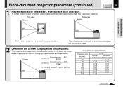
... - Adjust the projection size by changing the distances as a table. Continued Floor-mounted projector placement (continued) 1 Place the projector on a steady, level surface such as shown below. The projection size depends on the screen. Top view Screen Side view Screen CONTENTS 18 90° 90° Installation and connection Point the lens straight at the center of the screen as above. Screen a (min.) = Projection size - 1.6017 27.041 a (max.) = Projection size - 1.2699 21.463 a: Distance...
... - Adjust the projection size by changing the distances as a table. Continued Floor-mounted projector placement (continued) 1 Place the projector on a steady, level surface such as shown below. The projection size depends on the screen. Top view Screen Side view Screen CONTENTS 18 90° 90° Installation and connection Point the lens straight at the center of the screen as above. Screen a (min.) = Projection size - 1.6017 27.041 a (max.) = Projection size - 1.2699 21.463 a: Distance...
Owners Manual
Page 19
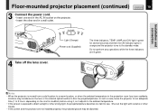
... three indicators are not installed properly, the projected picture may condense on the projector. • Insert the other end in a wall outlet. ON LAMP ON / STANDBY TEMP FAN Light (Orange) Power cord (Supplied) The three indicators, TEMP, LAMP, and ON, light in green for an adequate time (1 to 2 hours, depending on the room's condition) before using it, so it adjusts to the ambient temperature. • If the screen is moved from a cold location to a warm location, or...
... three indicators are not installed properly, the projected picture may condense on the projector. • Insert the other end in a wall outlet. ON LAMP ON / STANDBY TEMP FAN Light (Orange) Power cord (Supplied) The three indicators, TEMP, LAMP, and ON, light in green for an adequate time (1 to 2 hours, depending on the room's condition) before using it, so it adjusts to the ambient temperature. • If the screen is moved from a cold location to a warm location, or...
Owners Manual
Page 23
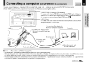
... connection cables. Connecting a Mac adapter for RGB input (analog RGB (1)/analog RGB (2)/digital RGB) and Y/PB/PR input. Use of connection cables that there is no guaranty of the operations not specified in the proper direction. Installation and connection Connecting a computer (COMPUTER IN 2 connector) CONTENTS 23 You can project the picture of analog RGB or digital RGB signal from factory, it is set for use as Analog RGB (2) input. Check that the power for the projector...
... connection cables. Connecting a Mac adapter for RGB input (analog RGB (1)/analog RGB (2)/digital RGB) and Y/PB/PR input. Use of connection cables that there is no guaranty of the operations not specified in the proper direction. Installation and connection Connecting a computer (COMPUTER IN 2 connector) CONTENTS 23 You can project the picture of analog RGB or digital RGB signal from factory, it is set for use as Analog RGB (2) input. Check that the power for the projector...
Owners Manual
Page 28
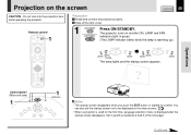
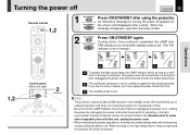
Remote control INPUT ON/STANDBY LASER KEYSTONE AUTO SET 1 L-CLICK R-CLICK VOLUME/ADJUST Preparation 1 Install and connect the projector properly. 2 Take off the lens cover. 1 ON/STANDBY Press ON/STANDBY. TEMP FAN (Green) MENU ENTER EXIT PIP FREEZE CALL RESIZE MUTE Control panel (Main unit side) 1 ON LAMP ON / STANDBY TEMP FAN 1 Indicators MENU ENTER EXIT AUTO SET INPUT VOL / ADJ Notes • The startup screen disappears when you push the EXIT button or waited for the first time, language selection menu is warming up...
Remote control INPUT ON/STANDBY LASER KEYSTONE AUTO SET 1 L-CLICK R-CLICK VOLUME/ADJUST Preparation 1 Install and connect the projector properly. 2 Take off the lens cover. 1 ON/STANDBY Press ON/STANDBY. TEMP FAN (Green) MENU ENTER EXIT PIP FREEZE CALL RESIZE MUTE Control panel (Main unit side) 1 ON LAMP ON / STANDBY TEMP FAN 1 Indicators MENU ENTER EXIT AUTO SET INPUT VOL / ADJ Notes • The startup screen disappears when you push the EXIT button or waited for the first time, language selection menu is warming up...
Owners Manual
Page 29
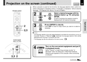
... you turn on the power. Select "Cancel" or install "plug and play monitor" of Windows(R) when the dialog box of Add New Hardware Wizard screen appears on the screen (continued) CONTENTS 29 Remote control INPUT ON/STANDBY LASER KEYSTONE AUTO SET When a projector is used for displaying menus or messages, is displayed with the selection button ( / ), and press ENTER ENTER. L-CLICK R-CLICK VOLUME/ADJUST MENU ENTER EXIT PIP FREEZE CALL RESIZE MUTE 2 2,3 Control panel...
... you turn on the power. Select "Cancel" or install "plug and play monitor" of Windows(R) when the dialog box of Add New Hardware Wizard screen appears on the screen (continued) CONTENTS 29 Remote control INPUT ON/STANDBY LASER KEYSTONE AUTO SET When a projector is used for displaying menus or messages, is displayed with the selection button ( / ), and press ENTER ENTER. L-CLICK R-CLICK VOLUME/ADJUST MENU ENTER EXIT PIP FREEZE CALL RESIZE MUTE 2 2,3 Control panel...
Owners Manual
Page 31
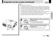
... to DDC2B (Display Data Channel 2B). Focus on the computer model. It is recommended to set the external monitor connected to the computer to XGA mode (1024 x 768). • The projector can be projected properly, depending on the picture by turning the focusing ring. Turn to the right to the DDC, start up your computer is recommended for the computer used. • The projector projects an image by XGA signal (1024...
... to DDC2B (Display Data Channel 2B). Focus on the computer model. It is recommended to set the external monitor connected to the computer to XGA mode (1024 x 768). • The projector can be projected properly, depending on the picture by turning the focusing ring. Turn to the right to the DDC, start up your computer is recommended for the computer used. • The projector projects an image by XGA signal (1024...
Owners Manual
Page 33
... Operations KEYSTONE Remote control INPUT ON/STANDBY LASER KEYSTONE AUTO SET 1,2 L-CLICK R-CLICK VOLUME/ADJUST MENU ENTER EXIT PIP FREEZE CALL RESIZE MUTE 1,2 INPUT Control panel (Main unit side) ON LAMP ON / STANDBY TEMP FAN 2 Indicators MENU ENTER VOL / ADJ EXIT AUTO SET 1 ON/STANDBY Press ON/STANDBY after a while. We recommend you may not light and the duration life will be turned back on ON/STANDBY the screen and disappears after using the projector for long periods of power in orange.) ON LAMP (Green) (Orange...
... Operations KEYSTONE Remote control INPUT ON/STANDBY LASER KEYSTONE AUTO SET 1,2 L-CLICK R-CLICK VOLUME/ADJUST MENU ENTER EXIT PIP FREEZE CALL RESIZE MUTE 1,2 INPUT Control panel (Main unit side) ON LAMP ON / STANDBY TEMP FAN 2 Indicators MENU ENTER VOL / ADJ EXIT AUTO SET 1 ON/STANDBY Press ON/STANDBY after a while. We recommend you may not light and the duration life will be turned back on ON/STANDBY the screen and disappears after using the projector for long periods of power in orange.) ON LAMP (Green) (Orange...
Owners Manual
Page 36
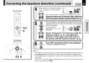
... the keystone correction setting or the contents of the signal source. • The adjustable range of "V-keystone" or "H-keystone" is not installed with the angle of 90 to the screen viewing from the menu with the selection button ( / ). Operations KEYSTONE L-CLICK R-CLICK VOLUME/ADJUST MENU ENTER EXIT PIP FREEZE CALL RESIZE MUTE 4,5 6 Control panel (Main unit side) ON LAMP ON / STANDBY TEMP FAN MENU ENTER VOL / ADJ EXIT AUTO SET 4,5 6 5 6 EXIT EXIT When the projector is...
... the keystone correction setting or the contents of the signal source. • The adjustable range of "V-keystone" or "H-keystone" is not installed with the angle of 90 to the screen viewing from the menu with the selection button ( / ). Operations KEYSTONE L-CLICK R-CLICK VOLUME/ADJUST MENU ENTER EXIT PIP FREEZE CALL RESIZE MUTE 4,5 6 Control panel (Main unit side) ON LAMP ON / STANDBY TEMP FAN MENU ENTER VOL / ADJ EXIT AUTO SET 4,5 6 5 6 EXIT EXIT When the projector is...
Owners Manual
Page 41
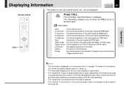
... RGB input) Sync - CONTENTS 41 Remote control INPUT ON/STANDBY LASER KEYSTONE AUTO SET L-CLICK R-CLICK VOLUME/ADJUST CALL MENU ENTER EXIT PIP FREEZE CALL RESIZE MUTE CALL Press CALL. the color mode of the firmware Shutter - the horizontal resolution of the input signal (at Y/PB/PR input) Lamp time - the vertical frequency of the input signal (at RGB input) V-frequency - Displaying Information Information on . • The information display turns off when the CALL button is used for lamp replacement...
... RGB input) Sync - CONTENTS 41 Remote control INPUT ON/STANDBY LASER KEYSTONE AUTO SET L-CLICK R-CLICK VOLUME/ADJUST CALL MENU ENTER EXIT PIP FREEZE CALL RESIZE MUTE CALL Press CALL. the color mode of the firmware Shutter - the horizontal resolution of the input signal (at Y/PB/PR input) Lamp time - the vertical frequency of the input signal (at RGB input) V-frequency - Displaying Information Information on . • The information display turns off when the CALL button is used for lamp replacement...
Owners Manual
Page 45
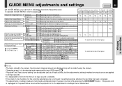
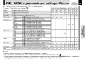
.... GUIDE MENU adjustments and settings CONTENTS 45 On GUIDE MENU, you can be adjusted and memorized for each RGB signal 71 . • "Keystone" and "Input source setting" can set ) at one input source are displayed only with its brightness Bright priority or quality (color) priority. Adjusting contrast of the picture Yes Yes Yes Yes Yes Yes Yes Adjust the image flicker. Adjusting brightness of the picture ADJ. Adjusting color deepness of the screen. Auto. The vertical keystone distortion is fixed...
.... GUIDE MENU adjustments and settings CONTENTS 45 On GUIDE MENU, you can be adjusted and memorized for each RGB signal 71 . • "Keystone" and "Input source setting" can set ) at one input source are displayed only with its brightness Bright priority or quality (color) priority. Adjusting contrast of the picture Yes Yes Yes Yes Yes Yes Yes Adjust the image flicker. Adjusting brightness of the picture ADJ. Adjusting color deepness of the screen. Auto. The vertical keystone distortion is fixed...
Owners Manual
Page 46
... SET The video mode is fixed to XGA (1024 x 768 dot) resolution SET The picture is selected in "Video mode" or "Signal format". 51 • The adjustments or settings made are not memorized. Yes Yes Yes Yes Camera gain ADJ. Yes Screen size Full thru Wide SET The picture is turned off by pressing the ON/STANDBY button. If the power cord is unplugged or if a power failure occurs while the projector is on, the adjustments or settings...
... SET The video mode is fixed to XGA (1024 x 768 dot) resolution SET The picture is selected in "Video mode" or "Signal format". 51 • The adjustments or settings made are not memorized. Yes Yes Yes Yes Camera gain ADJ. Yes Screen size Full thru Wide SET The picture is turned off by pressing the ON/STANDBY button. If the power cord is unplugged or if a power failure occurs while the projector is on, the adjustments or settings...
Owners Manual
Page 51
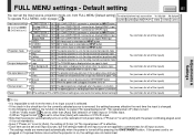
... the ceiling-mounted rear projection mode Yes (common for all of the inputs) No signal background Logo Blue background None SET The TOSHIBA logo is displayed when no signal is input SET A blue color is displayed at one input source are returned to the factory default setting Yes (common for all of the inputs) Adjustments & Settings Notes • It is impossible to exit from the menu if no input source is selected. • If the check in the check...
... the ceiling-mounted rear projection mode Yes (common for all of the inputs) No signal background Logo Blue background None SET The TOSHIBA logo is displayed when no signal is input SET A blue color is displayed at one input source are returned to the factory default setting Yes (common for all of the inputs) Adjustments & Settings Notes • It is impossible to exit from the menu if no input source is selected. • If the check in the check...
Owners Manual
Page 53
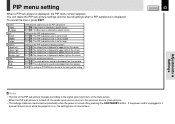
... the power cord is unplugged or if a power failure occurs while the projector is on the screen Selecting the audio input source SET : The main picture's sound is developed from the speaker SET : The sub picture's sound is developed from the speaker EXEC. Source Video S-Video Size Small Middle Large Position Upper left Upper right Bottom left Bottom right Audio Main Sub Reset Selecting the signal source for PIP sub-picture SET : Video input is selected as signal source SET : S-Video input...
... the power cord is unplugged or if a power failure occurs while the projector is on the screen Selecting the audio input source SET : The main picture's sound is developed from the speaker SET : The sub picture's sound is developed from the speaker EXEC. Source Video S-Video Size Small Middle Large Position Upper left Upper right Bottom left Bottom right Audio Main Sub Reset Selecting the signal source for PIP sub-picture SET : Video input is selected as signal source SET : S-Video input...
Owners Manual
Page 62
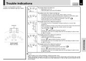
...; Clean the air filter. 63 (Lit in orange) • Unplug the power cord and reattach the lamp cover. 67 * The icon appears before the power turned off or does not come on. → Malfunction of the unit. • Unplug the power cord and call the dealer. Indicators ON LAMP ON / STANDBY TEMP FAN MENU ENTER VOL / ADJ EXIT AUTO SET Control panel (Main unit side) INPUT ON LAMP TEMP FAN (Off) Or (Lit in about 2 minutes. Trouble indications...
...; Clean the air filter. 63 (Lit in orange) • Unplug the power cord and reattach the lamp cover. 67 * The icon appears before the power turned off or does not come on. → Malfunction of the unit. • Unplug the power cord and call the dealer. Indicators ON LAMP ON / STANDBY TEMP FAN MENU ENTER VOL / ADJ EXIT AUTO SET Control panel (Main unit side) INPUT ON LAMP TEMP FAN (Off) Or (Lit in about 2 minutes. Trouble indications...
Owners Manual
Page 68
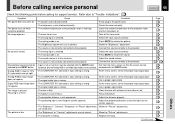
... calling service personal CONTENTS 68 Check the following points before asking for the proper input signal type. No image appears. • The lens cover is on. • The wrong input is selected. • The muting mode is on . • The sound volume is at its darkest. • The source is not correctly connected to the projector. Clean the lens with the INPUT button. Make the "Picture" adjustments. At the menu screen, set...
... calling service personal CONTENTS 68 Check the following points before asking for the proper input signal type. No image appears. • The lens cover is on. • The wrong input is selected. • The muting mode is on . • The sound volume is at its darkest. • The source is not correctly connected to the projector. Clean the lens with the INPUT button. Make the "Picture" adjustments. At the menu screen, set...
Owners Manual
Page 79
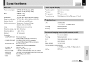
...crystal display Projection system Panel size Driving system Picture elements 3-panels transmission 0.9 inches TFT active matrix 786,432 pixels (1024 x 768 dots) (H./V.) x 3 Projection lens Lens Focusing Zooming Zooming lens F=1.7 to 2.1 f=33.6 to 42mm Manual operation Manual operation Document imaging camera (with camera model) Lens F = 3.1, f = 6.4mm Focusing Manual operation Zoom None (adjusted by distance to 35 deg. to subject) Iris Auto./Manual Image element 1/2 inch CCD Effective pixels for pickup section 1,447,680 pixels (1392 x 1040 dots) (H./V.) Lighting LED light...
...crystal display Projection system Panel size Driving system Picture elements 3-panels transmission 0.9 inches TFT active matrix 786,432 pixels (1024 x 768 dots) (H./V.) x 3 Projection lens Lens Focusing Zooming Zooming lens F=1.7 to 2.1 f=33.6 to 42mm Manual operation Manual operation Document imaging camera (with camera model) Lens F = 3.1, f = 6.4mm Focusing Manual operation Zoom None (adjusted by distance to 35 deg. to subject) Iris Auto./Manual Image element 1/2 inch CCD Effective pixels for pickup section 1,447,680 pixels (1392 x 1040 dots) (H./V.) Lighting LED light...


