Service Manual
Page 1
When repairing any green product (s), use the parts described in Japan, December 2005 GREEN SERVICE MANUAL FILE NO. 330-200515GR DOCUMENT CAMERA TLP-C001 The above models are classified as green product (s) (*1), as indicated by the underlined serial number (s). This Service Manual describes replacement parts for green product (s). For (*1) and (*2) , see the next page. © TOSHIBA CORPORATION Published in this manual and lead-free solder (*2).
When repairing any green product (s), use the parts described in Japan, December 2005 GREEN SERVICE MANUAL FILE NO. 330-200515GR DOCUMENT CAMERA TLP-C001 The above models are classified as green product (s) (*1), as indicated by the underlined serial number (s). This Service Manual describes replacement parts for green product (s). For (*1) and (*2) , see the next page. © TOSHIBA CORPORATION Published in this manual and lead-free solder (*2).
Service Manual
Page 2
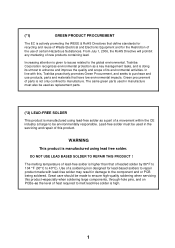
... USE LEAD BASED SOLDER TO REPAIR THIS PRODUCT ! The same green parts used in the servicing and repair of a movement within the CE industry at large to repair product made with this product. WARNING This product is manufactured using lead free solder. (*1) GREEN PRODUCT PROCUREMENT The EC is high. 1 Great care should be used as replacement parts. (*2) LEAD-FREE SOLDER This product is manufactured using lead-free...
... USE LEAD BASED SOLDER TO REPAIR THIS PRODUCT ! The same green parts used in the servicing and repair of a movement within the CE industry at large to repair product made with this product. WARNING This product is manufactured using lead free solder. (*1) GREEN PRODUCT PROCUREMENT The EC is high. 1 Great care should be used as replacement parts. (*2) LEAD-FREE SOLDER This product is manufactured using lead-free...
Service Manual
Page 3
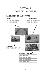
SECTION 1 PART REPLACEMENT 1.LOCATION OF MAIN PARTS ARM B001: SPRING+BEARING E001: ARM ASSEMBLY A003: CAMERA HEAD COVER KIT TOP COVER A001: TOP COVER ASSY U002: KEYPAD PCB U003: IR RECEIVER CAMERA E002: CAMERA HEAD ASSY BOTTOM COVER U001: MAIN PCB A002: BOTTOM COVER A005: FOOT, RUBBER A004: LABEL, SPEC 2
SECTION 1 PART REPLACEMENT 1.LOCATION OF MAIN PARTS ARM B001: SPRING+BEARING E001: ARM ASSEMBLY A003: CAMERA HEAD COVER KIT TOP COVER A001: TOP COVER ASSY U002: KEYPAD PCB U003: IR RECEIVER CAMERA E002: CAMERA HEAD ASSY BOTTOM COVER U001: MAIN PCB A002: BOTTOM COVER A005: FOOT, RUBBER A004: LABEL, SPEC 2
Service Manual
Page 4
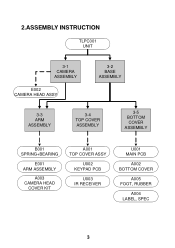
2.ASSEMBLY INSTRUCTION TLPC001 UNIT 3-1 CAMERA ASSEMBLY E002 CAMERA HEAD ASSY 3-2 BASE ASSEMBLY 3-3 ARM ASSEMBLY 3-4 TOP COVER ASSEMBLY 3-5 BOTTOM COVER ASSEMBLY B001 SPRING+BEARING E001 ARM ASSEMBLY A003 CAMERA HEAD COVER KIT A001 TOP COVER ASSY U002 KEYPAD PCB U003 IR RECEIVER U001 MAIN PCB A002 BOTTOM COVER A005 FOOT, RUBBER A004 LABEL, SPEC 3
2.ASSEMBLY INSTRUCTION TLPC001 UNIT 3-1 CAMERA ASSEMBLY E002 CAMERA HEAD ASSY 3-2 BASE ASSEMBLY 3-3 ARM ASSEMBLY 3-4 TOP COVER ASSEMBLY 3-5 BOTTOM COVER ASSEMBLY B001 SPRING+BEARING E001 ARM ASSEMBLY A003 CAMERA HEAD COVER KIT A001 TOP COVER ASSY U002 KEYPAD PCB U003 IR RECEIVER U001 MAIN PCB A002 BOTTOM COVER A005 FOOT, RUBBER A004 LABEL, SPEC 3
Service Manual
Page 5
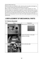
... servicing. To prevent missing, dropping, etc. Cautions Before Servicing Electronic parts are susceptible to static electricity and may easily be fixed. 3.REPLACEMENT OF MECHANICAL PARTS 3-1 Camera Assembly Step 1 Figure Explanation Remove four S-1 (force:1.8~2lb). 2 1.Tear off the sticker on the cable, 2.Remove the cable. 3 Remove the 3pin cable. 4 of them need special cautions. Many screws are used to secure...
... servicing. To prevent missing, dropping, etc. Cautions Before Servicing Electronic parts are susceptible to static electricity and may easily be fixed. 3.REPLACEMENT OF MECHANICAL PARTS 3-1 Camera Assembly Step 1 Figure Explanation Remove four S-1 (force:1.8~2lb). 2 1.Tear off the sticker on the cable, 2.Remove the cable. 3 Remove the 3pin cable. 4 of them need special cautions. Many screws are used to secure...
Service Manual
Page 6
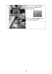
4 Remove the S-2 (force:2.8~3lb) that connected with "CAMERA HEAD ASSY"[23587758] Note: Go to 3-3 Arm Assembly for the further assembly instruction. 5
4 Remove the S-2 (force:2.8~3lb) that connected with "CAMERA HEAD ASSY"[23587758] Note: Go to 3-3 Arm Assembly for the further assembly instruction. 5
Service Manual
Page 8
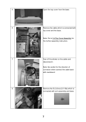
Note: Go to 3-4 Top Cover Assembly for the direction of connector when connect the cable back with mainboard 8 Remove the S-2 (force:2.8~3lb) which is connected with top cover and the base. Note: Be careful for the further assembly instruction. 7 Tear off the sticker on the cable and disconnect it. 5 Open the top cover from the base. 6 Remove the cable which is connected with arm assembly and base. 7
Note: Go to 3-4 Top Cover Assembly for the direction of connector when connect the cable back with mainboard 8 Remove the S-2 (force:2.8~3lb) which is connected with top cover and the base. Note: Be careful for the further assembly instruction. 7 Tear off the sticker on the cable and disconnect it. 5 Open the top cover from the base. 6 Remove the cable which is connected with arm assembly and base. 7
Service Manual
Page 10
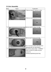
"CAMERA HEAD COVER KIT"[23587753] and remove the "SPRING+BEARING"[23587756] 9 3-3 Arm Assembly Step 1 Figure S-1 S-9 S-1 S-1 Explanation 1.Remove three S-1 (force:1.8~2lb) 2.Remove one S-9 (force:4.8~5lb) 2 Remove one S-1 (force:1.8~2lb) 3 Remove two S-6 (force:2.8~3lb) Note: The black rotation pad should be assembled with the right position. 4 Take off the camera head -
"CAMERA HEAD COVER KIT"[23587753] and remove the "SPRING+BEARING"[23587756] 9 3-3 Arm Assembly Step 1 Figure S-1 S-9 S-1 S-1 Explanation 1.Remove three S-1 (force:1.8~2lb) 2.Remove one S-9 (force:4.8~5lb) 2 Remove one S-1 (force:1.8~2lb) 3 Remove two S-6 (force:2.8~3lb) Note: The black rotation pad should be assembled with the right position. 4 Take off the camera head -
Service Manual
Page 11
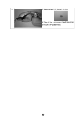
5 1.Remove two S-2 (force:2.8~3lb) 2.Take off the joint cover-"CAMERA HEAD COVER KIT"[23587753] 10
5 1.Remove two S-2 (force:2.8~3lb) 2.Take off the joint cover-"CAMERA HEAD COVER KIT"[23587753] 10
Service Manual
Page 12
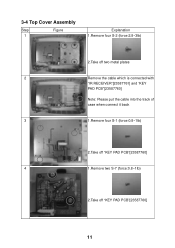
3-4 Top Cover Assembly Step 1 Figure Explanation 1.Remove four S-2 (force:2.8~3lb) 2.Take off two metal plates 2 Remove the cable which is connected with "IR RECEIVER"[23587761] and "KEY PAD PCB"[23587760] Note: Please put the cable into the track of case when connect it back 3 1.Remove four S-1 (force:0.8~1lb) 2.Take off "KEY PAD PCB"[23587760] 4 1.Remove two S-7 (force:0.8~1lb) 2.Take off "KEY PAD PCB"[23587760] 11
3-4 Top Cover Assembly Step 1 Figure Explanation 1.Remove four S-2 (force:2.8~3lb) 2.Take off two metal plates 2 Remove the cable which is connected with "IR RECEIVER"[23587761] and "KEY PAD PCB"[23587760] Note: Please put the cable into the track of case when connect it back 3 1.Remove four S-1 (force:0.8~1lb) 2.Take off "KEY PAD PCB"[23587760] 4 1.Remove two S-7 (force:0.8~1lb) 2.Take off "KEY PAD PCB"[23587760] 11
Service Manual
Page 14
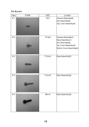
3-6 Screws Type S-1 FORM S-2 S-3 SIZE T2x7 Location Camera Assembly(4) Arm Assembly(4) Top Cover Assembly(4) T2.6x8 Camera Assembly(1) Base Assembly(1) Arm Assembly(2) Top Cover Assembly(4) Bottom Cover Assembly(4) T2.6x14 Base Assembly(5) S-4 T2.6x15 Base Assembly(2) S-5 M3x12 Base Assembly(2) 13
3-6 Screws Type S-1 FORM S-2 S-3 SIZE T2x7 Location Camera Assembly(4) Arm Assembly(4) Top Cover Assembly(4) T2.6x8 Camera Assembly(1) Base Assembly(1) Arm Assembly(2) Top Cover Assembly(4) Bottom Cover Assembly(4) T2.6x14 Base Assembly(5) S-4 T2.6x15 Base Assembly(2) S-5 M3x12 Base Assembly(2) 13
Service Manual
Page 16
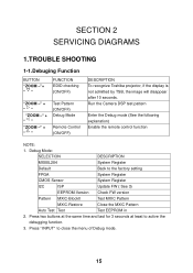
... 1.TROUBLE SHOOTING 1-1.Debuging Function BUTTON "ZOOM -"+ " " FUNCTION EDID checking (ON/OFF) "ZOOM -" + " " "ZOOM -" + " " "ZOOM -" + " " Test Pattern (ON/OFF) Debug Mode Remote Control (ON/OFF) DESCRIPTION To recognize Toshiba projector, if the display is not admitted by TSB, the image will disappear after 10 seconds. Debug Mode: SELECTION DESCRIPTION MX88L284 System Register Default Back to close the menu of Debug mode. 15 Press "INPUT" to the factory setting...
... 1.TROUBLE SHOOTING 1-1.Debuging Function BUTTON "ZOOM -"+ " " FUNCTION EDID checking (ON/OFF) "ZOOM -" + " " "ZOOM -" + " " "ZOOM -" + " " Test Pattern (ON/OFF) Debug Mode Remote Control (ON/OFF) DESCRIPTION To recognize Toshiba projector, if the display is not admitted by TSB, the image will disappear after 10 seconds. Debug Mode: SELECTION DESCRIPTION MX88L284 System Register Default Back to close the menu of Debug mode. 15 Press "INPUT" to the factory setting...
Service Manual
Page 17
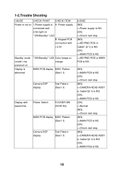
Keypad PCB connection with waved line Flicker Switch FLICKER SW (50/60 Hz) MAIN PCB display MXIC Pattern (See1-1) Camera DSP display Test Pattern (See1-1) JUDGE (NG) =>Power supply is NG (OK) =>Check next step (NG) =>KEYPAD PCB or Cable1 (2-1) is NG (...1-2.Trouble Shooting CAUSE CHECK POINT CHECK ITEM Power is not on orange MAIN PCB display MXIC Pattern (See1-1) Camera DSP display Test Pattern (See1-1) Display with +3.3V Standby mode couldn't be powered on Display is abnormal "ON/Standby" LED Color keeps on 1.Power supply is NG 16 Power supply connected well. 2.No light ...
Keypad PCB connection with waved line Flicker Switch FLICKER SW (50/60 Hz) MAIN PCB display MXIC Pattern (See1-1) Camera DSP display Test Pattern (See1-1) JUDGE (NG) =>Power supply is NG (OK) =>Check next step (NG) =>KEYPAD PCB or Cable1 (2-1) is NG (...1-2.Trouble Shooting CAUSE CHECK POINT CHECK ITEM Power is not on orange MAIN PCB display MXIC Pattern (See1-1) Camera DSP display Test Pattern (See1-1) Display with +3.3V Standby mode couldn't be powered on Display is abnormal "ON/Standby" LED Color keeps on 1.Power supply is NG 16 Power supply connected well. 2.No light ...
Service Manual
Page 18
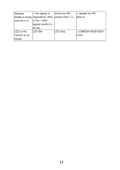
Message 1.The display is Check the FW display is wrong magnified to 190% version (See 1-1) when turn on 2.The "190%" appear position is wrong LED on the LED SW LED lamp Camera is not lighted =>Update the FW (See 3) =>CAMERA HEAD ASSY is NG 17
Message 1.The display is Check the FW display is wrong magnified to 190% version (See 1-1) when turn on 2.The "190%" appear position is wrong LED on the LED SW LED lamp Camera is not lighted =>Update the FW (See 3) =>CAMERA HEAD ASSY is NG 17
Service Manual
Page 19
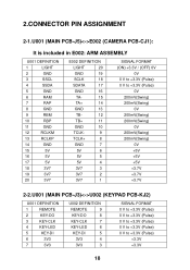
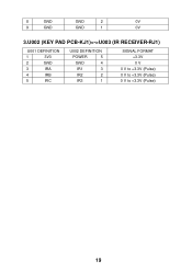
...CONNECTOR PIN ASSIGNMENT 2-1.U001 (MAIN PCB-J5)E002 (CAMERA PCB-CJ1): It is included in E002: ARM ASSEMBLY U001 DEFINITION 1 LIGHT 2 GND 3 SSCL 4 SSDA 5 GND 6 RAM 7 RAP 8 GND 9 RBM 10 RBP 11 GND 12 RCLKM 13 RCLKP 14 GND 15 5V 16 5V 17 5V 18 3V7 19 3V7 20 3V7 E002 DEFINITION LIGHT...7V +3.7V +3.7V 2-2.U001 (MAIN PCB-J3)U002 (KEYPAD PCB-KJ2) U001 DEFINITION 1 REMOTE 2 KEY-DO 3 KEY-CLK 4 KEY-LED 5 KEY-DI 6 3V3 7 3V3 U002 DEFINITION REMOTE 9 KEY-DO 8 KEY-CLK 7 KEY-LED 6 KEY-DI 5 3V3 4 3V3 3 SIGNAL FORMAT 0 V to +3.3V (Pulse)...
...CONNECTOR PIN ASSIGNMENT 2-1.U001 (MAIN PCB-J5)E002 (CAMERA PCB-CJ1): It is included in E002: ARM ASSEMBLY U001 DEFINITION 1 LIGHT 2 GND 3 SSCL 4 SSDA 5 GND 6 RAM 7 RAP 8 GND 9 RBM 10 RBP 11 GND 12 RCLKM 13 RCLKP 14 GND 15 5V 16 5V 17 5V 18 3V7 19 3V7 20 3V7 E002 DEFINITION LIGHT...7V +3.7V +3.7V 2-2.U001 (MAIN PCB-J3)U002 (KEYPAD PCB-KJ2) U001 DEFINITION 1 REMOTE 2 KEY-DO 3 KEY-CLK 4 KEY-LED 5 KEY-DI 6 3V3 7 3V3 U002 DEFINITION REMOTE 9 KEY-DO 8 KEY-CLK 7 KEY-LED 6 KEY-DI 5 3V3 4 3V3 3 SIGNAL FORMAT 0 V to +3.3V (Pulse)...
Service Manual
Page 20
8 GND GND 2 0V 9 GND GND 1 0V 3.U002 (KEY PAD PCB-KJ1)U003 (IR RECEIVER-RJ1) U001 DEFINITION 1 3V3 2 GND 3 IRA 4 IRB 5 IRC U002 DEFINITION POWER 5 GND 4 IR1 3 IR2 2 IR3 1 SIGNAL FORMAT +3.3V 0 V 0 V to +3.3V (Pulse) 0 V to +3.3V (Pulse) 0 V to +3.3V (Pulse) 19
8 GND GND 2 0V 9 GND GND 1 0V 3.U002 (KEY PAD PCB-KJ1)U003 (IR RECEIVER-RJ1) U001 DEFINITION 1 3V3 2 GND 3 IRA 4 IRB 5 IRC U002 DEFINITION POWER 5 GND 4 IR1 3 IR2 2 IR3 1 SIGNAL FORMAT +3.3V 0 V 0 V to +3.3V (Pulse) 0 V to +3.3V (Pulse) 0 V to +3.3V (Pulse) 19
Service Manual
Page 21
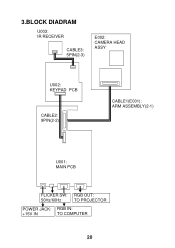
3.BLOCK DIADRAM U003: IR RECEIVER CABLE3: 5PIN(2-3) E002: CAMERA HEAD ASSY U002: KEYPAD PCB CABLE2: 9PIN(2-2) CABLE1(E001): ARM ASSEMBLY(2-1) U001: MAIN PCB FLICKER SW: RGB OUT: 50Hz/60Hz TO PROJECTOR POWER JACK: RGB IN: +15V IN TO COMPUTER 20
3.BLOCK DIADRAM U003: IR RECEIVER CABLE3: 5PIN(2-3) E002: CAMERA HEAD ASSY U002: KEYPAD PCB CABLE2: 9PIN(2-2) CABLE1(E001): ARM ASSEMBLY(2-1) U001: MAIN PCB FLICKER SW: RGB OUT: 50Hz/60Hz TO PROJECTOR POWER JACK: RGB IN: +15V IN TO COMPUTER 20
Service Manual
Page 24
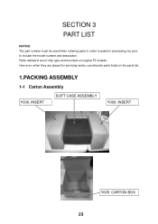
How ever, when they are of chip type and mounted on the parts list. 1.PACKING ASSEMBLY 1-1 Carton Assembly Y006: INSERT SOFT CASE ASSEMBLY Y006: INSERT Y005: CARTON BOX 23 SECTION 3 PART LIST NOTICE The part number must be used when ordering parts in order to assist in processing, be sure to include the model number and description. Parts marked # are placed for servicing works, use discrete parts listed on original PC boards.
How ever, when they are of chip type and mounted on the parts list. 1.PACKING ASSEMBLY 1-1 Carton Assembly Y006: INSERT SOFT CASE ASSEMBLY Y006: INSERT Y005: CARTON BOX 23 SECTION 3 PART LIST NOTICE The part number must be used when ordering parts in order to assist in processing, be sure to include the model number and description. Parts marked # are placed for servicing works, use discrete parts listed on original PC boards.
Service Manual
Page 28
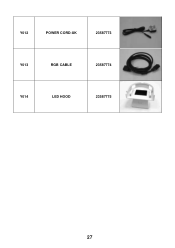
Y012 POWER CORD-UK 23587773 Y013 RGB CABLE 23587774 Y014 LED HOOD 23587775 27
Y012 POWER CORD-UK 23587773 Y013 RGB CABLE 23587774 Y014 LED HOOD 23587775 27
Service Manual
Page 30
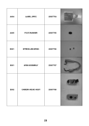
A004 LABEL,SPEC 23587754 A005 FOOT,RUBBER 23587755 B001 SPRING+BEARING 23587756 E001 ARM ASSEMBLY 23587757 E002 CAMERA HEAD ASSY 23587758 29
A004 LABEL,SPEC 23587754 A005 FOOT,RUBBER 23587755 B001 SPRING+BEARING 23587756 E001 ARM ASSEMBLY 23587757 E002 CAMERA HEAD ASSY 23587758 29


