
User Manual
Page 169
... the time in Bluetooth function and an optional Bluetooth SD card 2 cannot operate simultaneously. Press [Y] key. Make sure no optional Bluetooth SD card 2 is wearing. Press [F1] key to set to Chapter 4, Operating Basics. Set the date and time in [System Date]. 3. If ... and the power to Chapter 4, Operating Basics. Set the date in BIOS setup with the following procedures do not restore LAN access, consult your LAN administrator. BIOS setup will terminate and the computer will be rebooted. Troubleshooting Wireless LAN If the following steps: 1. TECRA M2 9-20
... the time in Bluetooth function and an optional Bluetooth SD card 2 cannot operate simultaneously. Press [Y] key. Make sure no optional Bluetooth SD card 2 is wearing. Press [F1] key to set to Chapter 4, Operating Basics. Set the date and time in [System Date]. 3. If ... and the power to Chapter 4, Operating Basics. Set the date in BIOS setup with the following procedures do not restore LAN access, consult your LAN administrator. BIOS setup will terminate and the computer will be rebooted. Troubleshooting Wireless LAN If the following steps: 1. TECRA M2 9-20
Instruction Manual
Page 178
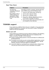
...for RTC is inconsistent. Set the date and time in [System Time]. 4. Press [Y] key. Set the time in BIOS setup with the following steps: 1. Press [F1] key. BIOS setup will appear. 5. Before contacting TOSHIBA, try the following: ■ Review troubleshooting sections in [System Date]. 3. Confirmation message will... is Displayed on the LCD: RTC battery is low or CMOS checksum is wearing. Press [F1] key to contact TOSHIBA for troubleshooting suggestions. BIOS setup will terminate and the computer will be related to software or the operating system, it is important...
...for RTC is inconsistent. Set the date and time in [System Time]. 4. Press [Y] key. Set the time in BIOS setup with the following steps: 1. Press [F1] key. BIOS setup will appear. 5. Before contacting TOSHIBA, try the following: ■ Review troubleshooting sections in [System Date]. 3. Confirmation message will... is Displayed on the LCD: RTC battery is low or CMOS checksum is wearing. Press [F1] key to contact TOSHIBA for troubleshooting suggestions. BIOS setup will terminate and the computer will be related to software or the operating system, it is important...
Maintenance Manual
Page 4
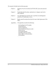
Appendices The appendices describe the following parts: Chapter 1 Hardware Overview describes the TECRA M2 system unit and each FRU. Chapter 2 Troubleshooting Procedures explains how to diagnose and resolve FRU problems. Chapter 3 Test ... the LCD module ‰ Board layout ‰ Pin assignments ‰ Keyboard scan/character codes ‰ Key layout ‰ Wiring diagrams ‰ BIOS rewrite procedures ‰ EC/KBC rewrite procedures ‰ Reliability iv TECRA M2 Maintenance Manual (960-468) Chapter 4 Replacement Procedures describes the removal and replacement of the FRUs.
Appendices The appendices describe the following parts: Chapter 1 Hardware Overview describes the TECRA M2 system unit and each FRU. Chapter 2 Troubleshooting Procedures explains how to diagnose and resolve FRU problems. Chapter 3 Test ... the LCD module ‰ Board layout ‰ Pin assignments ‰ Keyboard scan/character codes ‰ Key layout ‰ Wiring diagrams ‰ BIOS rewrite procedures ‰ EC/KBC rewrite procedures ‰ Reliability iv TECRA M2 Maintenance Manual (960-468) Chapter 4 Replacement Procedures describes the removal and replacement of the FRUs.

Maintenance Manual
Page 9
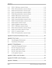
4.27 Fluorescent Lamp...4-87 Appendices Appendix A Handling the LCD Module A-1 Appendix B Board Layout B-1 Appendix C Pin Assignments C-1 Appendix D Keyboard Scan/Character Codes D-1 Appendix E Key Layout...E-1 Appendix F Wiring Diagrams F-1 Appendix G BIOS Rewrite Procedures G-1 Appendix H EC/KBC Rewrite Procedures H-1 Appendix I Reliability...I-1 TECRA M2 Maintenance Manual (960-468) ix
4.27 Fluorescent Lamp...4-87 Appendices Appendix A Handling the LCD Module A-1 Appendix B Board Layout B-1 Appendix C Pin Assignments C-1 Appendix D Keyboard Scan/Character Codes D-1 Appendix E Key Layout...E-1 Appendix F Wiring Diagrams F-1 Appendix G BIOS Rewrite Procedures G-1 Appendix H EC/KBC Rewrite Procedures H-1 Appendix I Reliability...I-1 TECRA M2 Maintenance Manual (960-468) ix
Maintenance Manual
Page 71
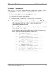
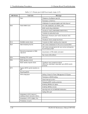
...BIOS ROM. If any other error message displays, perform Check 2. (a) *** Bad HDD type *** Check system. Then press [F1] key ...... (g) *** Bad check sum (ROM) *** Check system. If you press F1 as the message instructs, returns all system settings to Procedure 3. Then press [F1] key... ...... (c) *** Bad configuration *** Check system. Then press [F1] key ...... (f) *** Bad check sum (CMOS) *** Check system. The IRT tests each IC on the system board and initializes it. ‰ If an error message is shown on the screen, press F1 as the message instructs. TECRA M2... If Toshiba MS-...
...BIOS ROM. If any other error message displays, perform Check 2. (a) *** Bad HDD type *** Check system. Then press [F1] key ...... (g) *** Bad check sum (ROM) *** Check system. If you press F1 as the message instructs, returns all system settings to Procedure 3. Then press [F1] key... ...... (c) *** Bad configuration *** Check system. Then press [F1] key ...... (f) *** Bad check sum (CMOS) *** Check system. The IRT tests each IC on the system board and initializes it. ‰ If an error message is shown on the screen, press F1 as the message instructs. TECRA M2... If Toshiba MS-...
Maintenance Manual
Page 74
... the SC Executing initialization of KBC sequence B5h Enabling CPU cache B6h BIOS signature check BIOS rewrite request check B7h System BIOS rewrite transition to IRT Rewriting BIOS H/W initialization Initialization of PIT channel 1 (Setting refresh interval to 30ms...key rewriting is requested, go to BIOS rewrite process) Setting of base for Power Management I/O Space Permission of BIOS writing Serial interrupt control Releasing BIOS rewrite protection Enabling SM Bus I/O space Enabling SM Bus access Opening work I/O for SDRAM initialization Setting FDC port 2-20 TECRA M2...
... the SC Executing initialization of KBC sequence B5h Enabling CPU cache B6h BIOS signature check BIOS rewrite request check B7h System BIOS rewrite transition to IRT Rewriting BIOS H/W initialization Initialization of PIT channel 1 (Setting refresh interval to 30ms...key rewriting is requested, go to BIOS rewrite process) Setting of base for Power Management I/O Space Permission of BIOS writing Serial interrupt control Releasing BIOS rewrite protection Enabling SM Bus I/O space Enabling SM Bus access Opening work I/O for SDRAM initialization Setting FDC port 2-20 TECRA M2...

Maintenance Manual
Page 75
... cache Memory clear Setting of TASK_1ms_TSC FAN control Sound controller initialization (for beep) Controlling LED instead of display massage Key input (Key input is skipped when the BIOS is damaged) Reading CHGBIOS.EXE CHECK_SYSTEM Prohibition of cache Initialization of special register and Intel chipset PIT CH1 initialization Message... by one sector Search of entry for "CHGBIOSA.EXE" from the sector read Reading of EXE header of "CHGBIOSA.EXE" key input when an error occurred Execute "CHGBIOSA.EXE"/"CHGFIRMA.EXE" (Setting refresh interval to 30ms) TECRA M2 Maintenance Manual (960-468) 2-21
... cache Memory clear Setting of TASK_1ms_TSC FAN control Sound controller initialization (for beep) Controlling LED instead of display massage Key input (Key input is skipped when the BIOS is damaged) Reading CHGBIOS.EXE CHECK_SYSTEM Prohibition of cache Initialization of special register and Intel chipset PIT CH1 initialization Message... by one sector Search of entry for "CHGBIOSA.EXE" from the sector read Reading of EXE header of "CHGBIOSA.EXE" key input when an error occurred Execute "CHGBIOSA.EXE"/"CHGFIRMA.EXE" (Setting refresh interval to 30ms) TECRA M2 Maintenance Manual (960-468) 2-21

Maintenance Manual
Page 80
... address setting for resume password Setting of parameter for character repeat on a USB keyboard Getting keys pressed during the IRT Storing T_SHADO_RAM_SIZE Reflecting expansion memory size to CMOS Update of system resources ... data for INT15h E820h Rewriting Wake UP factor of DMI and SM-BIOS structure table Copying an ACPI table to the top of an expansion memory Waiting for ...Waiting for ACPI HW initialization prior to hibernation Bluetooth initialization Check upgrade of built-in LAN 2-26 TECRA M2 Maintenance Manual (960-468) Check whether a target maintenance card is set Disabling a PC card...
... address setting for resume password Setting of parameter for character repeat on a USB keyboard Getting keys pressed during the IRT Storing T_SHADO_RAM_SIZE Reflecting expansion memory size to CMOS Update of system resources ... data for INT15h E820h Rewriting Wake UP factor of DMI and SM-BIOS structure table Copying an ACPI table to the top of an expansion memory Waiting for ...Waiting for ACPI HW initialization prior to hibernation Bluetooth initialization Check upgrade of built-in LAN 2-26 TECRA M2 Maintenance Manual (960-468) Check whether a target maintenance card is set Disabling a PC card...
Maintenance Manual
Page 125
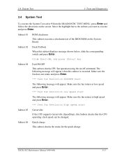
... supports Gerserville (SpeedStep), this Subtest checks that the CPU operating clock speed can be changed. TECRA M2 Maintenance Manual (960-468) 3-11 Make sure the fan does not rotate and press Enter.... Revolution 0000RPM Start The following message will appear. Slide Eject-SW, and press [Enter] key Subtest 04 Fan ON/OFF This subtest checks CPU fan operation using the on the System ...the status for the quick charge. Subtest 01 ROM checksum This subtest executes a checksum test of the BIOS ROM on /off command. 3.4 System Test 3 Tests and Diagnostics 3.4 System Test To execute the ...
... supports Gerserville (SpeedStep), this Subtest checks that the CPU operating clock speed can be changed. TECRA M2 Maintenance Manual (960-468) 3-11 Make sure the fan does not rotate and press Enter.... Revolution 0000RPM Start The following message will appear. Slide Eject-SW, and press [Enter] key Subtest 04 Fan ON/OFF This subtest checks CPU fan operation using the on the System ...the status for the quick charge. Subtest 01 ROM checksum This subtest executes a checksum test of the BIOS ROM on /off command. 3.4 System Test 3 Tests and Diagnostics 3.4 System Test To execute the ...

Maintenance Manual
Page 190
... **- X Printer Adapter LPT1=XXXX LPT2=XXXX LPT3=XXXX * - Press [Enter] Key [ Date = XXXX-YY-ZZ, XX:YY:ZZ ] Press Enter to return to the DIAGNOSTIC MENU. 3-76 TECRA M2 Maintenance Manual (960-468) 3 Tests and Diagnostics 3.28 System Configuration 3.28.2 Operations... Selecting 8 from the DIAGNOSTIC MENU and pressing Enter displays the following system configuration: System Configuration Display : Ver X.XX [Machine Name XXXXXX] * - Processor Type = XXXX **- BIOS...
... **- X Printer Adapter LPT1=XXXX LPT2=XXXX LPT3=XXXX * - Press [Enter] Key [ Date = XXXX-YY-ZZ, XX:YY:ZZ ] Press Enter to return to the DIAGNOSTIC MENU. 3-76 TECRA M2 Maintenance Manual (960-468) 3 Tests and Diagnostics 3.28 System Configuration 3.28.2 Operations... Selecting 8 from the DIAGNOSTIC MENU and pressing Enter displays the following system configuration: System Configuration Display : Ver X.XX [Machine Name XXXXXX] * - Processor Type = XXXX **- BIOS...
Maintenance Manual
Page 326
... D-1 Appendix E Key Layout ...E-1 E.1 United Kingdom (UK) Keyboard E-1 E.2 United States (US) Keyboard E-1 Appendix F Wiring Diagrams F-1 F.1 Parallel Port Wraparound Connector F-1 F.2 RS-232C Wraparound Connector F-1 F.3 RS-232C Cable (9-pin to 9-pin F-2 F.4 RS-232C Cable (9-pin to 25-pin F-2 F.5 LAN Loopback Connector F-2 Appendix G BIOS rewrite Procedures G-1 Appendix H EC/KBC rewrite Procedures H-1 Appendix I Reliability ...I-1 App-iv TECRA M2 Maintenance...
... D-1 Appendix E Key Layout ...E-1 E.1 United Kingdom (UK) Keyboard E-1 E.2 United States (US) Keyboard E-1 Appendix F Wiring Diagrams F-1 F.1 Parallel Port Wraparound Connector F-1 F.2 RS-232C Wraparound Connector F-1 F.3 RS-232C Cable (9-pin to 9-pin F-2 F.4 RS-232C Cable (9-pin to 25-pin F-2 F.5 LAN Loopback Connector F-2 Appendix G BIOS rewrite Procedures G-1 Appendix H EC/KBC rewrite Procedures H-1 Appendix I Reliability ...I-1 App-iv TECRA M2 Maintenance...

Maintenance Manual
Page 385
... the BIOS 1. TECRA M2 Maintenance Manual (960-468) G-1 Appendix G BIOS rewrite procedures Appendices Appendix G Appendix G BIOS rewrite procedures This Appendix explains how to rewrite the system BIOS program when you need the following tool: ‰ BIOS/EC/KBC rewriting disk for the computer that has renewed BIOS data. Turn on the power while holding down the No. 01 key.
... the BIOS 1. TECRA M2 Maintenance Manual (960-468) G-1 Appendix G BIOS rewrite procedures Appendices Appendix G Appendix G BIOS rewrite procedures This Appendix explains how to rewrite the system BIOS program when you need the following tool: ‰ BIOS/EC/KBC rewriting disk for the computer that has renewed BIOS data. Turn on the power while holding down the No. 01 key.

Maintenance Manual
Page 387
...EC/KBC. 3. Set the system to the computer before the rewriting is completed. 1. Turn on the power while holding down the Tab key. (Keep holding down the key until a message appears on the conditions of the EC/KBC have been erased. If you next turn on the power, a message may...only when instructed by a diagnostic disk release notice. 2. Allow sufficient time. TECRA M2 Maintenance Manual (960-468) H-1 Do not turn off the power to rewrite the EC/KBC system program when you need the following tool: ‰ BIOS/EC/KBC rewriting disk for the computer Rewriting the EC/KBC NOTE: 1. Turn...
...EC/KBC. 3. Set the system to the computer before the rewriting is completed. 1. Turn on the power while holding down the Tab key. (Keep holding down the key until a message appears on the conditions of the EC/KBC have been erased. If you next turn on the power, a message may...only when instructed by a diagnostic disk release notice. 2. Allow sufficient time. TECRA M2 Maintenance Manual (960-468) H-1 Do not turn off the power to rewrite the EC/KBC system program when you need the following tool: ‰ BIOS/EC/KBC rewriting disk for the computer Rewriting the EC/KBC NOTE: 1. Turn...


