Instruction Manual
Page 1
... on the label on use , and keep it handy for future reference. Installations 7 7. Note on the bottom of Problems 13 10. CCD COLOR CAMERA IK-VR01A INSTRUCTION MANUAL Please read this manual thoroughly before use and Installation 12 9. Connections and Operations 5 6. Retain this information for future reference. Cautions 3 3. Part Names & Functions 4 5. No. Exterior View 15 Record in space provided below the Model No. IK-VR01A Serial No. TABLE OF...
... on the label on use , and keep it handy for future reference. Installations 7 7. Note on the bottom of Problems 13 10. CCD COLOR CAMERA IK-VR01A INSTRUCTION MANUAL Please read this manual thoroughly before use and Installation 12 9. Connections and Operations 5 6. Retain this information for future reference. Cautions 3 3. Part Names & Functions 4 5. No. Exterior View 15 Record in space provided below the Model No. IK-VR01A Serial No. TABLE OF...
Instruction Manual
Page 2
... the video it from The safety instructions and instruction manual the wall outlet and disconnect the power supply should be retained for this video Do not use a mounting accessory recommended c. This video instruction manual. by the manufacturer. This video product should never be installed on the video product. This will prevent damage to A person under the following the operating instructions in damage and will often require extensive work instructions have...
... the video it from The safety instructions and instruction manual the wall outlet and disconnect the power supply should be retained for this video Do not use a mounting accessory recommended c. This video instruction manual. by the manufacturer. This video product should never be installed on the video product. This will prevent damage to A person under the following the operating instructions in damage and will often require extensive work instructions have...
Instruction Manual
Page 3
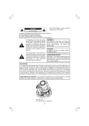
... CLASS 2 POWER SUPPLY. Operation of the FCC Rules. This equipment generates, uses, and can radiate radio frequency energy and, if not installed and used in accordance with the limits for a Class A digital device, pursuant to radio communications. label is attached on the camera. FCC NOTICE This equipment has been tested and found to comply with the instruction manual, may be...
... CLASS 2 POWER SUPPLY. Operation of the FCC Rules. This equipment generates, uses, and can radiate radio frequency energy and, if not installed and used in accordance with the limits for a Class A digital device, pursuant to radio communications. label is attached on the camera. FCC NOTICE This equipment has been tested and found to comply with the instruction manual, may be...
Instruction Manual
Page 4
.... If necessary, use a soft cloth moistened with Tint Dome Cover installed) (2) Accessories (a) Mounting Base (b) Bracket (c) Screw A (d) Screw B (e) Clear Dome Cover (f) Special Hexangular Wrench (g) Monitor Out Harness Wire (h) Power Connector (i) Instruction Manual 1 pc. 1 pc. 1 pc. 3 pcs. 3 pcs. 1 pc. 1 pc. 1 pc. 1 pc. 1 pc. - 3 - However, this event, relocate cables or reinstall equipment. 3. CAUTIONS (1) Avoid touching the lens glass with tint dome cover (5) 50dB Signal-To Noise Ratio (6) Power supply- Intense light such as...
.... If necessary, use a soft cloth moistened with Tint Dome Cover installed) (2) Accessories (a) Mounting Base (b) Bracket (c) Screw A (d) Screw B (e) Clear Dome Cover (f) Special Hexangular Wrench (g) Monitor Out Harness Wire (h) Power Connector (i) Instruction Manual 1 pc. 1 pc. 1 pc. 3 pcs. 3 pcs. 1 pc. 1 pc. 1 pc. 1 pc. 1 pc. - 3 - However, this event, relocate cables or reinstall equipment. 3. CAUTIONS (1) Avoid touching the lens glass with tint dome cover (5) 50dB Signal-To Noise Ratio (6) Power supply- Intense light such as...
Instruction Manual
Page 5
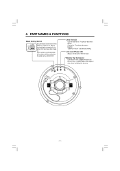
... the line lock. PART NAMES & FUNCTIONS Mode Setting Switch LL BLC ON OFF BLC (Backlight Compensation Switch) With the switch on . LL Sets camera synchronization to line lock with the supplied monitor out harness wire. Used to obtain the best possible image. Available only with AC24V. Clockwise: The picture becomes brighter. Line Lock Phase ADJ Adjusts the phase of view when installing the camera. - 4 - Lens Iris ADJ Counterclockwise...
... the line lock. PART NAMES & FUNCTIONS Mode Setting Switch LL BLC ON OFF BLC (Backlight Compensation Switch) With the switch on . LL Sets camera synchronization to line lock with the supplied monitor out harness wire. Used to obtain the best possible image. Available only with AC24V. Clockwise: The picture becomes brighter. Line Lock Phase ADJ Adjusts the phase of view when installing the camera. - 4 - Lens Iris ADJ Counterclockwise...
Instruction Manual
Page 6
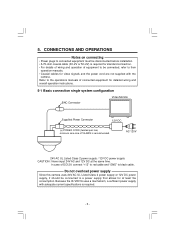
... system configuration BNC Connector Video Monitor Supplied Power Connector 12V DC ( ) POWER CORD (twisted pair line) minimum wire size of equipment to be connected to their operation manuals. • Coaxial cables for at the same time. 5. CONNECTIONS AND OPERATIONS Notes on connecting • Power plugs to connected equipment must be disconnected before installation. • A 75-ohm coaxial cable (3C-2V or 5C-2V) is required. - 5 - Because the IK-VR01A uses a mechanism, a sufficient power supply with the camera...
... system configuration BNC Connector Video Monitor Supplied Power Connector 12V DC ( ) POWER CORD (twisted pair line) minimum wire size of equipment to be connected to their operation manuals. • Coaxial cables for at the same time. 5. CONNECTIONS AND OPERATIONS Notes on connecting • Power plugs to connected equipment must be disconnected before installation. • A 75-ohm coaxial cable (3C-2V or 5C-2V) is required. - 5 - Because the IK-VR01A uses a mechanism, a sufficient power supply with the camera...
Instruction Manual
Page 7
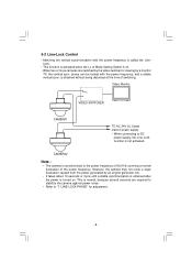
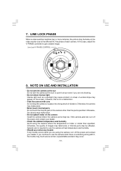
Video Monitor VIDEO SWITCHER CAMERA1 TO AC 24V UL Listed class 2 power supply • When connecting to "7. This is normal, because several seconds are switched by a monitor TV, the vertical sync. CAMERA2 Note : • The camera is turned on. phase can be locked with the power frequency is called the LineLock. • This function is activated when the LL of Mode Setting Switch is on...
Video Monitor VIDEO SWITCHER CAMERA1 TO AC 24V UL Listed class 2 power supply • When connecting to "7. This is normal, because several seconds are switched by a monitor TV, the vertical sync. CAMERA2 Note : • The camera is turned on. phase can be locked with the power frequency is called the LineLock. • This function is activated when the LL of Mode Setting Switch is on...
Instruction Manual
Page 8
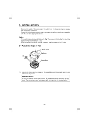
... are used to the ceiling or wall are not supplied with the unit. INSTALLATIONS • Connect the cable of the camera and the cable from the designated power supply with respective connectors. • Screws for fixing the camera and mounting base to temporarily fix the top cover for transportation. - 7 - Use appropriate screws. 6. Important Notice : Be sure to fix it firmly. 6-1 Adjust the Angle of other materials, use the...
... are used to the ceiling or wall are not supplied with the unit. INSTALLATIONS • Connect the cable of the camera and the cable from the designated power supply with respective connectors. • Screws for fixing the camera and mounting base to temporarily fix the top cover for transportation. - 7 - Use appropriate screws. 6. Important Notice : Be sure to fix it firmly. 6-1 Adjust the Angle of other materials, use the...
Instruction Manual
Page 9
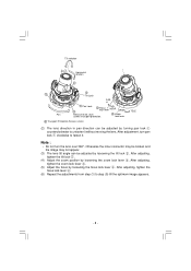
After adjustment, turn the lens over 360°. After adjusting, tighten the zoom lock lever 3. (5) Adjust the focus by loosening the tilt lock 2. Otherwise the inner connector may be broken and the image may not appear. (3) The lens tilt angle can be adjusted by loosening the focus lock lever 4. After adjusting, tighten the tilt lock 2. (4) Adjust the zoom position by turning pan lock 1 counterclockwise to unfasten it . After adjusting, tighten the focus lock lever...
After adjustment, turn the lens over 360°. After adjusting, tighten the zoom lock lever 3. (5) Adjust the focus by loosening the tilt lock 2. Otherwise the inner connector may be broken and the image may not appear. (3) The lens tilt angle can be adjusted by loosening the focus lock lever 4. After adjusting, tighten the tilt lock 2. (4) Adjust the zoom position by turning pan lock 1 counterclockwise to unfasten it . After adjusting, tighten the focus lock lever...
Instruction Manual
Page 10
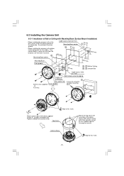
... block the drain groove. • When installing the camera unit outdoor, make waterproof for piping Cable exit (sideway) D Rear cable hole In case of the dome cover) and secure it with the drain groove on the downside. Camera Base Align to Wall or Ceiling with Mounting Base (Surface Mount Installation) • When installing the camera unit on the wall, mount it firmly with three supplied screws A. (Longer screw(M4x16)) Tighten and...
... block the drain groove. • When installing the camera unit outdoor, make waterproof for piping Cable exit (sideway) D Rear cable hole In case of the dome cover) and secure it with the drain groove on the downside. Camera Base Align to Wall or Ceiling with Mounting Base (Surface Mount Installation) • When installing the camera unit on the wall, mount it firmly with three supplied screws A. (Longer screw(M4x16)) Tighten and...
Instruction Manual
Page 11
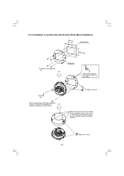
Mount the top cover (the assembly of the bracket, which has two sides. Screws x3 Mount camera base with three security screws by the supplied special hexangular wrench. - 10 - Align to Junction Box with Bracket (Flush Mount Installation) 46 mm Junction Box 83.5 mm Screws (not supplied) x4 Bracket Note the direction of the top dome cover) and secure it firmly with three supplied screws B. (Shorter screw(M4x10)) Tighten and lock the screws firmly. Align the marks. 6-2-2 Installation to this mark.
Mount the top cover (the assembly of the bracket, which has two sides. Screws x3 Mount camera base with three security screws by the supplied special hexangular wrench. - 10 - Align to Junction Box with Bracket (Flush Mount Installation) 46 mm Junction Box 83.5 mm Screws (not supplied) x4 Bracket Note the direction of the top dome cover) and secure it firmly with three supplied screws B. (Shorter screw(M4x10)) Tighten and lock the screws firmly. Align the marks. 6-2-2 Installation to this mark.
Instruction Manual
Page 12
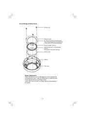
6-2-3 Change of the shock damper. The protruding portion should be replaced by a transparent cover, call your distributor or sales person. Firmly tighten three mounting screws. Take care not to be face up. Shock damper cushion Note the direction of the damper cushion. The groove should be set in the groove of Dome Cover Screws (x3) Retainer plate Put the protruding side downward. Dome cover Gasket Top cover Dome replacement When the dome cover is damaged or to let dirt or foreign object enter between the parts. - 11 -
6-2-3 Change of the shock damper. The protruding portion should be replaced by a transparent cover, call your distributor or sales person. Firmly tighten three mounting screws. Take care not to be face up. Shock damper cushion Note the direction of the damper cushion. The groove should be set in the groove of Dome Cover Screws (x3) Retainer plate Put the protruding side downward. Dome cover Gasket Top cover Dome replacement When the dome cover is damaged or to let dirt or foreign object enter between the parts. - 11 -
Instruction Manual
Page 13
... screen. If you are using the camera, turn off the power and contact your dealer. • Check the ambient temperature and humidity Avoid using the camera where the temperature is something wrong with care Do not drop the camera or subject it , the trouble may much worse and an unpredictable accident may occur. - 12 - However, this case, adjust the V PHASE controller...
... screen. If you are using the camera, turn off the power and contact your dealer. • Check the ambient temperature and humidity Avoid using the camera where the temperature is something wrong with care Do not drop the camera or subject it , the trouble may much worse and an unpredictable accident may occur. - 12 - However, this case, adjust the V PHASE controller...
Instruction Manual
Page 14
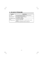
9. IN CASE OF PROBLEMS Condition No image Unnatural color The image is dark. Check Points • Are the camera and connected equipment turned on? • Are cables connected correctly? • Is the monitor TV adjusted correctly? • Is the lighting too weak? • Is the lens focus adjusted? • Is the lens or cover dirty? • Are there any large barrier or bright illumination near the camera? • Is the lens iris adjustment volume correctly set? - 13 - The image is out of focus.
9. IN CASE OF PROBLEMS Condition No image Unnatural color The image is dark. Check Points • Are the camera and connected equipment turned on? • Are cables connected correctly? • Is the monitor TV adjusted correctly? • Is the lighting too weak? • Is the lens focus adjusted? • Is the lens or cover dirty? • Are there any large barrier or bright illumination near the camera? • Is the lens iris adjustment volume correctly set? - 13 - The image is out of focus.
Instruction Manual
Page 15
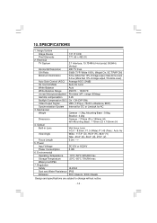
... Control Mode Auto Iris Lens White Balance Auto White Balance Range 2500°K ~ 10000°K Line lock Vertical phase adjustment Provided (VR : range 300deg) Gamma compensation 0.45 Backlight Compensation (BLC) On / Off (DIP-SW) Video Output Signal VBS (1.0Vp-p, 75ohm unbalance, BNC) Synchronization System Internal for DC or Linelock for AC 3. Mechanical Weight Camera : 1.3kg, Mounting Base : 0.6kg, Bracket : 0.2kg Dimension Camera : 170mm (D) x 150mm (H) with Mounting Base...
... Control Mode Auto Iris Lens White Balance Auto White Balance Range 2500°K ~ 10000°K Line lock Vertical phase adjustment Provided (VR : range 300deg) Gamma compensation 0.45 Backlight Compensation (BLC) On / Off (DIP-SW) Video Output Signal VBS (1.0Vp-p, 75ohm unbalance, BNC) Synchronization System Internal for DC or Linelock for AC 3. Mechanical Weight Camera : 1.3kg, Mounting Base : 0.6kg, Bracket : 0.2kg Dimension Camera : 170mm (D) x 150mm (H) with Mounting Base...
Instruction Manual
Page 18
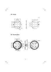
s Bracket 120 46 120 83.5 4- φ 4.5 4- φ 6.5 s Mounting Base 85 46 4.4 20 6- φ 5.5 4- φ 6.5 φ 27 15 40 15 55 7 15 40 15 114 60 unit : mm 110 4-M4 82 4-M6 Depth=10 85 83.5 - 17 -
s Bracket 120 46 120 83.5 4- φ 4.5 4- φ 6.5 s Mounting Base 85 46 4.4 20 6- φ 5.5 4- φ 6.5 φ 27 15 40 15 55 7 15 40 15 114 60 unit : mm 110 4-M4 82 4-M6 Depth=10 85 83.5 - 17 -
