
Quick Start Guide for for 0SU7033 KVM Switch 933210
Page 1
It's in PDF format on the supplied CD or on our website www.minicom.com in https, or SSH console. PX Serial is a one-port RS232/422/485 to Redundant Ethernet device .... The PX Serial components The package includes: 1 PX Serial unit 1 Power adapter (100-240VAC) Mounting kit foot pads Minicom CD 1111 W. 35th Street, Chicago, IL 60609 USA www.tripplite.com/support Copyright ©2012 Tripp Lite. PX Serial can be configured by a web browser in the Support section. Additional...
It's in PDF format on the supplied CD or on our website www.minicom.com in https, or SSH console. PX Serial is a one-port RS232/422/485 to Redundant Ethernet device .... The PX Serial components The package includes: 1 PX Serial unit 1 Power adapter (100-240VAC) Mounting kit foot pads Minicom CD 1111 W. 35th Street, Chicago, IL 60609 USA www.tripplite.com/support Copyright ©2012 Tripp Lite. PX Serial can be configured by a web browser in the Support section. Additional...

Quick Start Guide for for 0SU7033 KVM Switch 933210
Page 3
.... Connecting the PX Serial Connect the PX Serial to the power supply, the Network switch and Serial device as explained below. 5.1 Connecting the Power supply You can connect the PX Serial to the Power supply using the Terminal Block (PWR1) and/or the Power Jack (PWR2). On: Power is on and functioning normally. Blinking: Located by Administrator's Location...
.... Connecting the PX Serial Connect the PX Serial to the power supply, the Network switch and Serial device as explained below. 5.1 Connecting the Power supply You can connect the PX Serial to the Power supply using the Terminal Block (PWR1) and/or the Power Jack (PWR2). On: Power is on and functioning normally. Blinking: Located by Administrator's Location...
Quick Start Guide for for 0SU7033 KVM Switch 933210
Page 4
...LAN 2 LED turns orange for 10M Ethernet or green for 100M Ethernet. But if when the device starts up . see below . Once connected to the power supply, Power 1 LED turns red to show unit booting up only Ethernet port 2 is running correctly the LED turns green. 5.2 Connecting to the network switch Connect the... ports 1 and 2 can be connected to prevent the DC wires from coming loose - Tighten the terminal screws to different switches. contacts of your DC supply into the V+ and V- If both ports are connected when the device starts up . PX SERIAL 5.1.1 Terminal Block (PWR1) 1.
...LAN 2 LED turns orange for 10M Ethernet or green for 100M Ethernet. But if when the device starts up . see below . Once connected to the power supply, Power 1 LED turns red to show unit booting up only Ethernet port 2 is running correctly the LED turns green. 5.2 Connecting to the network switch Connect the... ports 1 and 2 can be connected to prevent the DC wires from coming loose - Tighten the terminal screws to different switches. contacts of your DC supply into the V+ and V- If both ports are connected when the device starts up . PX SERIAL 5.1.1 Terminal Block (PWR1) 1.
Owner's Manual for 0SU7033 KVM Switch 933209
Page 2
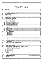
Restoring the default settings 7 9. Integrating the PX Serial into KVM.net ...3 3. PX Serial ports...4 5. Connecting the PX Serial 5 7.1 Connecting the Power supply 5 7.1.1 Terminal Block (PWR1)...6 7.1.2 Power Jack (PWR2)...6 7.2 Connecting to the network switch 6 7.3 Connecting to the Serial device 7 7.4 Configuring the dipswitches 7 8. Configuring the PX Serial unit 8 9.1 Basic settings ...9 9.2 Network Setting ...10 9.3 ...
Restoring the default settings 7 9. Integrating the PX Serial into KVM.net ...3 3. PX Serial ports...4 5. Connecting the PX Serial 5 7.1 Connecting the Power supply 5 7.1.1 Terminal Block (PWR1)...6 7.1.2 Power Jack (PWR2)...6 7.2 Connecting to the network switch 6 7.3 Connecting to the Serial device 7 7.4 Configuring the dipswitches 7 8. Configuring the PX Serial unit 8 9.1 Basic settings ...9 9.2 Network Setting ...10 9.3 ...

Owner's Manual for 0SU7033 KVM Switch 933209
Page 6
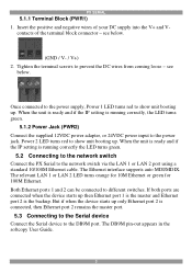
... condition exists. Connecting the PX Serial Connect the PX Serial to the power supply, the Network switch and Serial device as explained below. 7.1 Connecting the Power supply You can connect the PX Serial to the PX ears and mount on a wall. Blinking: Indicates an IP conflict, or ... DHCP or BOOTP server did not respond properly. Din-rail mounting Screw the din-rail Mounting clips to the Power supply using the Terminal Block (PWR1) and/or the Power Jack (PWR2). On: Power is on and booting up . Blinking: 100 Mbps Ethernet connection. PX Serial LEDs PX SERIAL LED PWR 1...
... condition exists. Connecting the PX Serial Connect the PX Serial to the power supply, the Network switch and Serial device as explained below. 7.1 Connecting the Power supply You can connect the PX Serial to the PX ears and mount on a wall. Blinking: Indicates an IP conflict, or ... DHCP or BOOTP server did not respond properly. Din-rail mounting Screw the din-rail Mounting clips to the Power supply using the Terminal Block (PWR1) and/or the Power Jack (PWR2). On: Power is on and booting up . Blinking: 100 Mbps Ethernet connection. PX Serial LEDs PX SERIAL LED PWR 1...

Owner's Manual for 0SU7033 KVM Switch 933209
Page 7
...If both ports are connected when the device starts up only Ethernet port 2 is running correctly, the LED turns green. 7.1.2 Power Jack (PWR2) Connect the supplied 12VDC power adapter, or 24VDC power input to the network switch via the LAN 1 or LAN 2 port using a standard 10/100M Ethernet cable. The relevant...positive and negative wires of the terminal block connector - see below . Power 2 LED turns red to show unit booting up . When the unit is ready and if the IP setting is the backup. Once connected to the power supply, Power 1 LED turns red to show unit booting up . USER GUIDE ...
...If both ports are connected when the device starts up only Ethernet port 2 is running correctly, the LED turns green. 7.1.2 Power Jack (PWR2) Connect the supplied 12VDC power adapter, or 24VDC power input to the network switch via the LAN 1 or LAN 2 port using a standard 10/100M Ethernet cable. The relevant...positive and negative wires of the terminal block connector - see below . Power 2 LED turns red to show unit booting up . When the unit is ready and if the IP setting is the backup. Once connected to the power supply, Power 1 LED turns red to show unit booting up . USER GUIDE ...